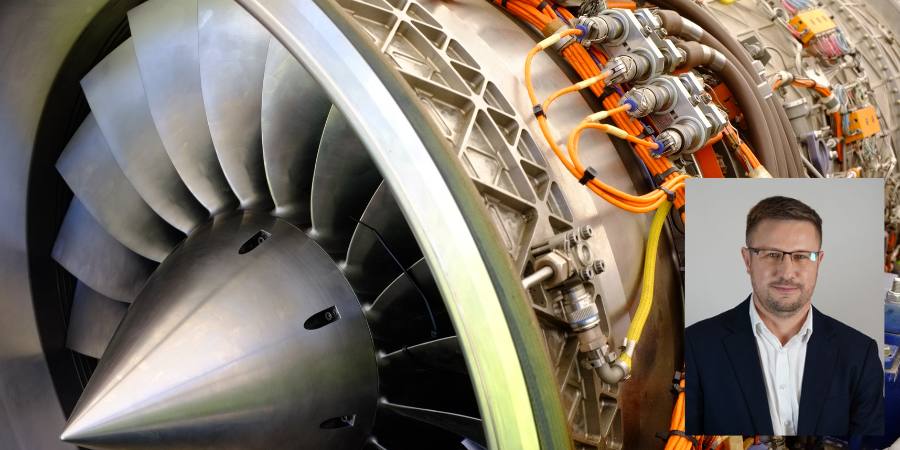
A global manufacturer of aircraft parts has ordered a single-chamber vacuum furnace for brazing jet engine parts. The new equipment will replace a 30-year-old unit previously operating in its Poland-based plant.
Jędrzej Malinowski Sales Manager SECO/WARWICK Group Source: LinkedIn
The new Vector® vacuum furnace is being supplied by SECO/WARWICK, which also manufactured the retiring equipment. The upgrade is based on a standard Vector vacuum furnace with a working space of 900 x 900 x 1200 mm, with screen insulation and metal heating elements. The solution has been adapted to industry specific needs and can heat treat jet engine components, such as complex gears or main shafts.
“This unit is distinguished by the ability to carry out efficient and clean high vacuum processes thanks to the use of a molybdenum heating chamber and a very efficient pumping system. This ensures very high purity and the dynamics required for brazing processes. Another big advantage is the very good temperature uniformity in the molybdenum heating chamber and compliance with the strict requirements of industry standards such as AMS2750,” said Jędrzej Malinowski, sales manager, SECO/WARWICK Group.
The press release is available in its original form here.
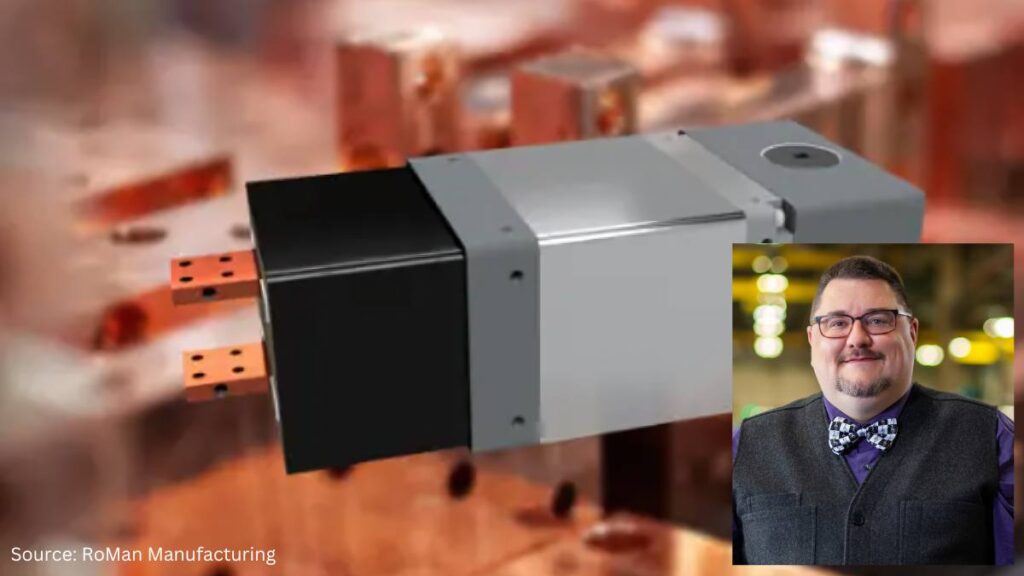
“Communication is key.” As heat treating equipment and processes evolve, it becomes critical that the accompanying control systems also develop to maintain “communication.” In this Technical Tuesday installment, guest columnist Stanley Rutkowski III, senior applications engineer at RoMan Manufacturing, Inc., discusses how digital control system communications have improved to increase energy efficiency for manufacturers with in-house heat treat operations.
This informative piece was first released inHeat Treat Today’sMay 2024 Sustainability Heat Treat print edition.
Industrial furnace applications that rely on resistive heating will consume large amounts of electrical energy when processing their loads. Utilizing digital controls technologies to maximize this type of heating allows for a cleaner-and thus greener-approach to energy demands.
Typically, heat treat processes have a long duration (hours to days in length), and each load can have its own unique recipe in the amount of power required. With unique recipes, there tends to be a ramp-up phase (getting the vessel to temperature), followed by a soak phase (which demands more control over the power system), and then a cool-down phase (an even more controlled state). As the power is controlled through the furnace system, disturbances occur with different technologies. This starts with “tube technology,” then variable reactance transformer (VRT) technology, then silicon controlled rectifier (SCR) technology, and finally IGBT (insulated-gate bipolar transistor) technology. As these technologies have evolved, their ability to communicate information digitally has allowed for less disturbance in the power system and allowing both a less expensive energy bill and a cleaner energy usage for the process.
Definitions
Electrical Power
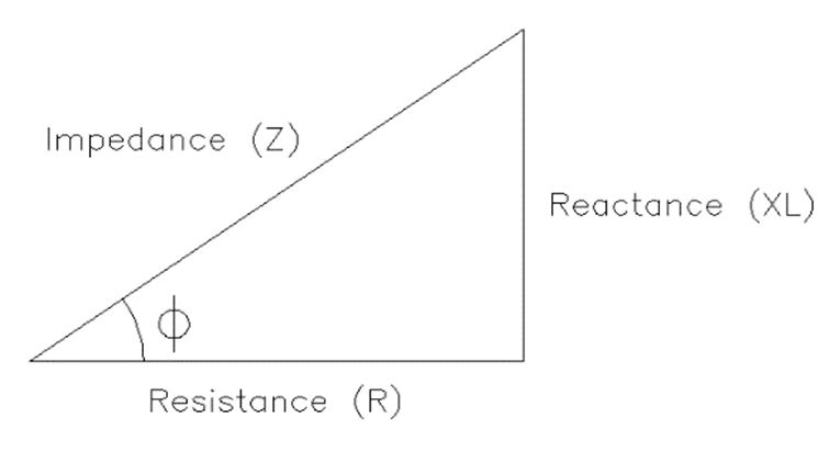
Power losses in an electrical system are defined by five aspects (Figure 1):
Resistance (R): a function of the material cross section and the length of an electrical conductor.
Reactance (XL): a function of the area in a circuit and is a vector 90 degrees offset from resistance.
Capacitance (XC): a vector 180 degrees offset from reactance. In inductive circuits, capacitance can be added for power factor correction.
Impedance (Z): the vector sum of resistance, reactance, and capacitance.
Power Factor [cos(F)]: the ratio of resistance to impedance. In industrial applications, displacement power factor (DPF), the offset of the current to voltage waveforms, is used in the billing of electrical power.
There are five unique aspects that define electrical power usage (Figure 2):
Real power (kW): the amount of power that is generated.
Reactive power (kVAR): the amount of power that is wasted.
Total power (kVA): the rate at which power is consumed. This is also referred to as apparent power.
Power factor (cos(F)): the ratio of real power to total power. In industrial applications, the displacement power factor (DPF) is the offset of the current to voltage waveforms and is used to bill for electrical power.
Peak demand: the capacity required when the power grid experiences the highest power demand in a specified period of time.
3 Most Popular Types of Control Systems
For the most part, today’s furnace manufacturers use three main types of control systems: VRT, SCR, and IGBT. Each operates with slightly different methods to control how power goes into the heat treat furnace and creates heat.
VRT Control System
One traditional resistance heating setup uses a VRT control system that incorporates a saturable reactor, which controls the power applied to the transformer in the system (Figure 3). The control transformer on the output side of the transformer feeds back to the reactor to set the limit on the input power to the transformer.
Figure 3. VRT Control and Transformer Schematic (CT=control transformer); Source: RoMan Manufacturing, Inc.
SCR Control System
Figure 4. SCR Control and Transformer Schematic; Source: RoMan Manufacturing, Inc.
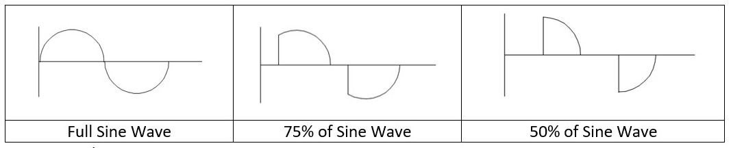
Another traditional resistance heating setup uses an SCR control system that includes dual thyristors (gated diodes) to control the amount of power applied to the primary of a transformer.
The SCR control delays the start of the waveform, and the control point is reset when the waveform crosses the zero line.
Figure 5. Comparison of Sine Waves; Source: RoMan Manufacturing, Inc.
IGBT Control System
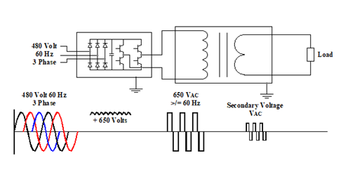
Finally, an IGBT control system uses a diode bridge, capacitor, and switching transistors to control the amount of power applied to the primary (i.e., main power input of a transformer). The input frequency to the transformer is controlled by the switching transistors. Since the IGBT control system utilizes all three phases of the power system, the IGBT control can be set to a particular phase for the zero cross (for phase orientation in the application, synchronous mode) or left floating (non-synchronous mode), as is demonstrated in Figure 6. The input voltage to the transformer is increased by the operation of the IGBT control. As such, potential energy savings may be had with these types of controls as compared to tradition controls (such as on-off contractors, time proportioning controls, or other types of current proportioning control systems).
Figure 6. IGBT Control and Transformer Schematic; Source: RoMan Manufacturing, Inc.
Synchronization with the IGBT can be to the incoming lines (A, B, or C phase) and can be offset from each of the phases. The ability to offset from a phase allows for traditional arrangements (Single Phase, Scott-T, Delta and Wye) as well as unique offsets allowing for additional vector heating in the application with AC outputs. The unique arrangements beyond the traditional systems could allow for more uniform heating of the part and less energy being consumed during the process.
Advantages of Utilizing Communications
As technology for controlling heating systems has evolved, and with an emphasis on clean energy sources, the ability to communicate with the control system has increased as well. This communication allows for more precise control of the run for the load, improved power usage (better power factors and less peak power usage as well as less total power usage), and inputs into a preventive maintenance program.
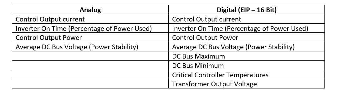
Table A. Analog vs. Digital IGBT Systems
With an IGBT system, both analogue and digital control communications are available today. See Table A for a comparison on how each control option works.
In addition to the EIP defined pieces, there is the ability to access the FPGA system for graphical outputs that can be downloaded into another system in your process for storage, comparisons, or general record keeping for a part run. The FPGA is an internal processor in the control that allows for more data, charting, and diagnostics to be captured and used by the system for both energy consumption and possible preventative maintenance purposes.
Why does this matter? Let’s turn to some possible ways of using the data generated from digital controls systems:
Evaluate average, minimum, and maximum DC bus voltages to plan for the best time and day to run heat treat jobs. For high power draw jobs, planning ahead can minimize power costs; similarly, knowing power trends can be helpful to plan jobs requiring sensitive control of the heating.
Evaluate transformer output voltage to allow the system to detect any shorts in the process. If the controller output and transformer output diverge from the known turns ratio, a change has occurred in the system. This could be corroborated if controller on time and output power do not trend.
Track furnace run records with EIP communications and FPGA data. This will be most helpful in processing lots of data, as is the case for Milspec records.
Evaluate changes in power factor to monitor any loose cables, and so avoid reactive power losses.
Evaluate the current versus the voltage to monitor the resistance of the system. If there is an increase in the resistance, you could project the trends in wear of the heating elements, therefore predicting future required maintenance.
Evaluate the critical control temperatures of the system to know if it is being run close to, or above, its ratings or if there is a disturbance in the cooling systems.
Use knowledge of power usages and power stability to update recipes for load runs so they use less power over the total run; this allows for a less costly power-savings solution. With less power usage, more output of the total facility can be had as each station contributes less to energy consumption
Even more benefits can be realized when users and builders of furnace systems and component manufacturers collaborate in the design of the total system. Such dialogues lead to the creation of more interactive and intuitive solutions that minimize power consumption, minimize downtime, and maximize outputs. These practical benefits are the foundation of a greener system.
About the Author:
Stanley F. Rutkowski III Senior Applications Engineer RoMan Manufacturing, Inc.
Stanley F. Rutkowski III is the senior applications engineer at RoMan Manufacturing, Inc., working on electrical energy savings in resistance heating applications. Stanley has worked at the company for 33 years with experience in welding, glass and furnace industries from R&D, design, and application standpoints. For more than 15 years, his focus has been on energy savings applications in industrial heating applications.
David Burritt president and CEO U.S. Steel Source: U.S. Steel
Access to technology and expertise in integrated mills are among the advantages that will accompany the U. S. Steel–Nippon Steel merger, according to David Burritt, U. S. Steel’s CEO. Heat treatment processes are an element in integrated mill operations within both companies’ profiles.
On December 18, 2023, it was announced that Japanese steelmaker Nippon Steel (NSC) would acquire Pittsburgh–based U. S. Steel. Under the deal, Nippon Steel would acquire the company for $14.1 billion, which totals to $14.9 billion when including the assumption of U.S. Steel’s debt. As part of the deal, Nippon Steel will invest $1.4 billion in U. S. Steel’s assets and will share technical knowledge, stated Burritt during his keynote address to the 2024 Global Steel Dynamics Forum.
“They’re experts in integrated mills, and they want to invest here,” he said.
In April, Nippon Steel released a statement that the merger will include U. S. Steel having access to Nippon’s technologies and R&D advancements, “help[ing] U. S. Steel produce more advanced and environmentally sustainable steel for domestic customers.”
Heat TreatToday offers News Chatter, a feature highlighting representative moves, transactions, and kudos from around the industry. Enjoy these 21 news items.
Equipment
Tata Steel Meramandali, based in Odisha, India, placed an order with SMS group for the implementation of Paul Wurth coke oven gas injection technology at their Blast Furnace (BF) #1. This order is the first of its kind in India, setting a precedent for the industry’s move towards sustainable steel production. The project is expected to be commissioned by Q1 2026 and will be completed within 25 months.
Sousa Corp., based in Newington, CT, installed its second Ipsen Turbo²Treater vacuum furnace to its production line, expanding its capacity to meet demand for heat treating services to the aerospace, automotive, medical, and general manufacturing industries.
A Chinese partner has purchased a two-chamber VIM 50 kg induction furnace from SECO/WARWICK for casting gas turbine blades. The furnace will produce gas turbine blade castings in an equiaxed structure and has already obtained an export license.
The modernization of a blast furnace at Salzgitter Flachstahl AG has been completed by SMS group. The new Paul Wurth parallel hopper Bell Less Top® (BLT) installed offers enhanced efficiency with less maintenance.
Edwards AFB in California received delivery of a composition oven from DELTA H®/Phillips Federal. The equipment will be used for advanced materials applications R&D. The heat treat furnace supplier initially designed and engineered the walk-in oven using SolidWorks 3D modeling and developed the project as a “kit oven” for easy field assembly. After preassembly of key subsystems at their Carroll, OH facility, the system was shipped to Edwards AFB. The entire field assembly project required two weeks including commissioning and extensive training of USAF personnel.
Tata Steel Nederland selected Tenova to develop a new state-of-the-art steel production line in IJmuiden, the Netherlands. The overall contract will include engineering, supply, and advisory services for a three million tons electric arc furnace to meet current operational specifications (high-quality steel for the automotive sector).
Cavendish Hydrogen ASA, a subsidiary of Nel ASA,has received a purchase order from Alperia Greenpower SRL for hydrogen fueling equipment to be used for light- and heavy-duty fuel cell electric vehicles in Bruneck, South Tyrol, Italy. This will be Nel’s first H2Station™ installation in Italy, built for the 2026 Winter Olympics to fuel vehicles for the transfer between the Olympic sports facilities.
Newly installed material hoppers at Salzgitter Flachstahl AGCoke oven gas compressing station previously installed at HKM, GermanyDELTA H®/Phillips Federal providing composite oven for Edwards AFBLeft to right: Paolo Stagnoli (Tenova), Hans van den Berg (CEO Tata Steel Nederland), Jeroen Klumper (Tata Steel Nederland), and Nico Bleijendaal (Danieli)
Company & Personnel
StandardAero has appointed Kim Ernzen to serve as chief operating officer. In this role, Ernzen reports directly to Russell Ford, StandardAero chairman and CEO, and is responsible for global operational performance, efficiency, and excellence, as well as engineering and supply chain management for StandardAero. Additionally, StandardAero’s Engine Services and Component Repair Services division presidents will report directly to Ernzen, who will maintain close oversight of the company’s overall business performance. She replaces Kerry O’Sullivan, who is retiring from StandardAero, and will be located at the company’s Scottsdale, Arizona, headquarters office.
Steelhead Technologies launched Steelhead University, an online learning platform designed to expedite user training and streamline software implementation. The comprehensive curriculum of eight core administrative courses equips users with fundamental knowledge essential for navigating the intricacies of the company’s software.
Solar Atmospheres’ newest acquisition, Solar Atmospheres of San Diego, has announced the addition of Chris Constable as their new vice president of operations. Chris has nearly 25 years of heat treating experience that includes quality, operations, management, plant safety, business development, and sales.
Ipsen USA welcomes Max Stormo as the new Ipsen customer service (ICS) operations manager as the company streamlines its aftermarket services in Souderton, PA. Stormo comes to Ipsen after an extensive career working as a manufacturing operations leader in Texas, and a recent role as vice president of operations at a manufacturer in the Philadelphia region.
Solar Manufacturing, Inc., announced the hiring of Nicholas Max, BSME Drexel University, as its chief mechanical engineer to head up its vacuum furnace mechanical design group. Nick is also pursuing an MBA at Lehigh University in Bethlehem, PA. He will be tasked to lead the further development of energy efficient hot zones, vacuum vessels, high pressure gas quenching systems, and vacuum pumping systems.
Ipsen USA has confirmed its commitment to the growth of the Ipsen Customer Service (ICS) Parts Department by expanding staff and implementing strategic initiatives. Christina Connelly, parts manager for Ipsen in Cherry Valley, joined the team in 2022, and has since hired six additional employees. Connelly and her veteran team members and new hires are focused on reducing turnaround time and increasing customer responsiveness.
Swiss Steel Group announced its participation in a renewable energy consortium, the “Initiative EE-Industrie.” This initiative, consisting of 19 small and medium-sized enterprises (SMEs) in Germany, aims to build, operate and utilize wind and photovoltaic plants for self-supply with green electricity.
Kanthal and Danieli have announced a partnership to jointly scale up Kanthal’s demonstrated electric process gas direct-heating solution, Prothal® DH, to full industrial scale. With the installation in Energiron hydrogen-ready DRI plants, fully green DRI production will be achieved. Additionally, the introduction of Prothal® DH technology in blast furnace operation will reduce CO2 emissions in ironmaking.
Kim Ernzen, Chief Operating Officer at StandardAero Screenshot of Steelhead University knowledge check on adjusting powder coat recipesChris Constable, Vice President of Operations, Solar Atmospheres of San DiegoMax Stormo, Customer Service Operations Manager, Ipsen USANicholas Max, Chief Mechanical Engineer, Solar Manufacturing, Inc.Dilip Chandrasekaran, Global Business Development Manager at Kanthal (L) and Marco Lapasin, Vice President Danieli Engineering Centro Metallics
Kudos
Ipsen Global has received the German Innovation Award for the Atlas Green furnace platform, presented by The German Design Council. The award ceremony was held in Frankfurt, Germany, on May 14, celebrating the innovators that emerged from a field of 520 submissions from across 23 countries.
Industrial Steel Treating Co. was named the Manufacturer of the Year by the Jackson Area (MI) Manufacturers Association. Accepting on behalf of IST was Tim Levy, current President of IST. Members of the Levy family in attendance included current VP, Tom Levy, and former IST President, Bernard Levy. Bernard was the 2nd generation Levy family owner and spent his entire 50-year career at IST before retiring and passing the reins to his three sons in 1998.
Bluestreak Compliance™, a division of Bluestreak | Bright AM™, received approval as a Registered Practitioner Organization (RPO) by the Cybersecurity Maturity Model Certification (CMMC) Accreditation Body (Cyber-AB). This significant achievement enables Bluestreak Compliance™ to offer expert consulting services to defense contractors and suppliers aiming to comply with CMMC cybersecurity standards and prepare for their Cybersecurity Maturity Model Certification (CMMC) audits.
IHEA has announced Dr. Avi Shultz as keynote at the first Industrial Heating Decarbonization SUMMIT. Dr. Shultz, Director of the U.S. Department of Energy’s Industrial Efficiency and Decarbonization Office (IEDO), will provide the keynote address at its first summit, to be held October 28-20 at the Conrad Indianapolis.
Swiss Steel Group has launched a new website which focuses on customer needs, including a Product Finder that generates automated product suggestions based on customer requirements and specifications, and detailed information about green initiatives and sustainability as well as special requirements for steel grades for specific applications.
IHEA recently announced its 2024–25 Board of Directors and Executive Officers. Taking over as President is Jeff Rafter of Selas Heat Technology Co. LLC; Vice-President is Gary Berwick of Dry Coolers, Inc.; and Treasurer is Jason Safarz of Karl Dungs, Inc. Brian Kelly of Honeywell Thermal Solutions assumes the Past President position. Finalizing the lineup of IHEA’s Board of Directors for 2024-2025, the following members continue their tenure: Scott Bishop, Electric Power Research Institute (EPRI); Bob Fincken, Super Systems, Inc.; Ben Gasbarre, Gasbarre Thermal Processing Systems; Doug Glenn, Heat Treat Today; John Podach, Fostoria Infrared; John Stanley, Karl Dungs, Inc.; Michael Stowe, Advanced Energy; Helen Tuttle, WS Thermal Process Technology Inc.; and Jeff Valuck, Surface Combustion, Inc.
Dr. Bora Ozkan-Paul van Doesburg (L) and Lutz Dietzold (R) with their German Innovation AwardTim Levy (L) and Bernard Levy (R)Dr. Avi Schultz, keynote speaker at IHEA’s Industrial Heating Decarbonization SUMMITThe 2024-25 IHEA Board of Directors: Back row, left to right; John Stanley, Bob Fincken, Gary Berwick, Brian Kelly, Scott Bishop, Doug Glenn, and Jeff Rafter. Front row, left to right; Jeff Valuck, Ben Gasbarre, Helen Tuttle, IHEA Executive Vice President Anne Goyer, Jason Safarz, and John Podach. Not pictured: Michael Stowe
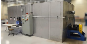
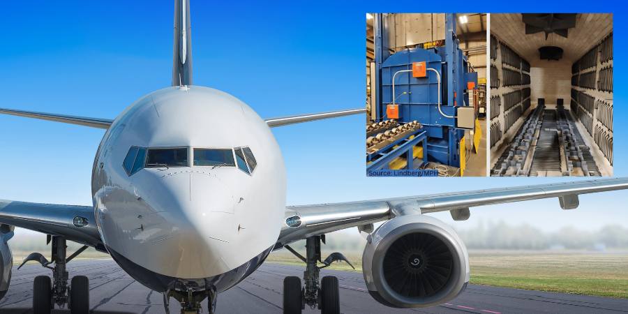
An aerospace company has purchased a rod overbend box furnace to heat treat parts under an inert atmosphere. The heat treating furnace has a maximum temperature rating of 2,000°F and a load capacity of 6,000 lbs.
The box furnace, which was manufactured and shipped by Michigan-based Lindberg/MPH, has an automated load transfer table and is designed to heat treat parts in a nitrogen atmosphere. A nitrogen gas flow meter controls the atmospheric conditions.
The box furnace includes an automated load transfer table. Under the table, five (5) fans with a variable-frequency drive provide accelerated cooling. The load table utilizes a pusher/puller mechanism to move parts trays in and out of the furnace.
The furnace’s radiant heating system uses heavy-gauge alloy rod over-bend heating elements mounted along the side walls and the floor. Two (2) Watlow F4T controllers control and record the furnace temperature, which allows for seven (7) zones of heating. The box furnace also meets Class 3 temperature uniformity of ±15°F at 1,000°F – 1,800°F.
The press release is available in its original form here.
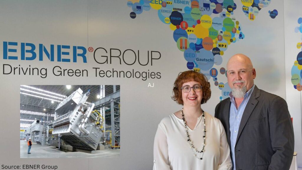
EBNER Group, a global provider of heat treatment solutions, melting, and casting for the aluminum industry has increased its stake in a furnace manufacturer, including annealing furnaces. GNA alutech inc. produces aluminum melting and holding furnaces, homogenizing and annealing furnaces, and cathode sealing equipment.
Robert Ebner CEO, EBNER Group Source: EBNER Group
“We are excited to announce the full acquisition of GNA alutech inc. and would like to thank GNA’s founder, Ted Phenix, for his vision and leadership in building GNA into a successful company over 41 years. Over the last 5 years I was always impressed by the deep understanding and knowledge Ted was able to share with customers. Our strong professional developed to a strong personal friendship,” said Robert Ebner, CEO of EBNER Group.
EBNER Group provides heat treatment solutions for the aluminum industry with the companies EBNER, ETS, EED, Gautschi, TPS, Hazelett, HPI, and GNA, increasing its stake in the latter to 100%. The acquisition marks the culmination of a five-year partnership between EBNER and Ted Phenix, which began with EBNER Group acquiring a majority stake in GNA in 2019.
The leadership of GNA has been placed in the hands of Kaleb Wright, president of business development, and Chantal Coupal, president of operations.
Pictured: Chantal Coupal, president of operations of GNA alutech, and Kaleb Wright, president of business development of GNA alutech
The press release is available in its original form here.
A discussion of laser heat treating begun in Heat Treat Today’s Air & Atmosphere 2024 print edition would not be complete without highlighting key sustainability advantages of this new technology. In this Technical Tuesday installment, guest columnist Aravind Jonnalagada (AJ), CTO and co-founder of Synergy Additive Manufacturing LLC, explores how sustainability and energy-efficiency are driven by precision heat application and minimal to zero distortion. The first part, “Advantages of Laser Heat Treatment: Precision, Consistency, and Cost Savings”, appeared on April 2, 2024, in Heat Treat Today, as well as in Heat Treat Today’s January/February 2024 Air & Atmosphere print edition.
This informative piece was first released inHeat Treat Today’sMay 2024 Sustainability Heat Treat print edition.
Laser heat treating is a transformative process that promises superior performance and sustainable practices. Laser heat treating epitomizes precision in surface heat treatment techniques, targeting localized heating of steel or cast-iron components. Laser radiation raises the surface temperature of the metal in the range of 1652°F to 2552°F (900°C to 1400°C), inducing a transformation from ferritic to austenitic structure on the metal surface. As the laser beam traverses the material, the bulk of the component self-quenches the heated zone. During this process, carbon particles are deposited in the high temperature lattice structure and cannot diffuse outward because of quick cool down resulting in the formation of hard martensite to a case depth up to 0.080” (2 mm), crucial for enhancing material properties.
Sustainability through Energy Efficiency
Contact us with your Reader Feedback!
When considering the energy consumption of a typical laser heat treating operation, it’s essential to acknowledge the continuous advancements in laser technology. Modern laser heat treating systems integrate high-power lasers, water chillers, and motion systems, such as robots or CNC machines. With a typical wall plug efficiency of around 50% for diode lasers, these systems represent a significant improvement in energy utilization compared to conventional methods. The typical energy consumption cost for running a 6 kW laser heat treating system is $20-$30/day. The calculation is based on an 8-hour shift with a duty cycle of 80% calculated at national average electric cost of 15.45 cents/kilowatt-hour.
Self-Quenching Mechanism
Laser heat treating operates on the essential principle of self-quenching, leveraging the bulk mass of the material for rapid cooling. This eliminates the dependence on quenchants required in flame and induction heat treating processes, further reducing environmental impact and operational costs.
Precision and Minimal Distortion
At the heart of laser heat treating lies its sustainable and energy-efficient attributes, driven by two fundamental features: precision heat application and minimal to zero distortion of components post-heat treatment. When compared to the conventional methods such as flame and induction hardening, laser heat treatment offers significantly localized heating. This precision allows for targeted heat treatment within millimeter precision right where the hardness is needed, optimizing energy utilization and operational efficiency. Furthermore, the high-power density of lasers enables hardening with minimal to zero distortion, eliminating or reducing the need for subsequent machining operations like hard milling or grinding.
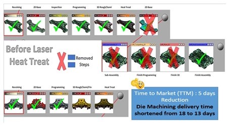
Comparison of the die construction process before and after laser hardening Source: Autodie LLC
A Case Study of Laser Heat Treating in Automotive Stamping Dies
The image above identifies process steps typically involved in construction of automotive stamping dies. During the process of manufacturing automotive stamping dies, the cast dies are first soft milled, intentionally leaving between 0.015” and 0.020” of extra stock material on the milled surfaces. This is done to account for any distortions that will result from the subsequent conventional heat treatment processes such as flame or induction. After heat treating, the dies are then hard milled back to tolerance and assembled.
In the laser heat treating process, by contrast, dies are finish machined to final tolerance in the first step and then laser heat treated without distortion. No secondary hard milling operation is necessary. Typical cost savings for our automotive tool and die customer exceeds over 20% due to elimination of hard milling operation. Total energy reduction is significant, although not computed here. This may result in savings if carbon credits become monetized.
Laser heat treating’s precision, efficiency, and minimal environmental footprint position it as an environmentally friendly option for heat treat operations. As industries continue to prioritize sustainability, laser heat treating may set new standards for excellence and environmental stewardship.
Aravind Jonnalagadda (AJ) is the CTO and co-founder of Synergy Additive Manufacturing LLC. With over 15 years of experience, AJ and Synergy Additive Manufacturing LLC provide high-level laser systems and laser heat treating, specializing in high power laser-based solutions for complex manufacturing challenges related to wear, corrosion, and tool life. Synergy provides laser systems and job shop services for laser heat treating, metal based additive manufacturing, and laser welding.
An aerospace, industrial gas turbine, and automotive market leader has expanded its heat treatment operations with a recently purchased air atmosphere furnace. Connecticut-based Doncaster Precision Castings will use the new furnace to support annealing, tempering, and heat treatment of steel and castings.
Doncaster Precision Castings previously received a similar model for use in its heavy-duty industrial processes within the aerospace and automotive sectors. The furnace, supplied by L&L Special Furnace, has a maximum temperature of 1850°F (1010°C) and a capacity to handle a typical load weight of 2,000 pounds.
The press release is available in its original form here.
Each year, the 40 Under 40 initiative at Heat Treat Todayrecognizes 40 rising young leaders (ages 40 and younger) in heat treat who are going above and beyond in the industry. The 40 Under 40 initiative gives names, faces, and words to the next generation of heat treat professionals.
To learn more about what makes someone a quality candidate for this honor, read below to hear from the individuals themselves — alumni of Heat Treat Today’s40 Under 40 — as they share personal updates and industry insights.
Click this link to nominate yourself, or someone you know, by June 28, 2024.
David Cunningham
At the time of David’s nomination for Heat TreatToday’s40 Under 40 Class of 2019, he was working in Process & Mechanical Design as a heat treating furnace engineer for L&L Special Furnace Co., Inc. Here he shares an exciting career (and company) update: “The biggest change since I was nominated to Heat Treat Today’s40 Under 40 is that I have taken over ownership of L&L Special Furnace Co. I became full owner of the business in January 2023.”
David Cunningham L&L Special Furnace, Co., Inc.
Something David finds most fascinating about the heat treat industry is the number of markets it serves. He says, “I am always surprised looking through our list of customers and knowing what their processes are. I never considered how many industries utilize heat treating.”
David’s advice for the incoming 40 Under 40Class of 2024 is to “Keep learning . . . there is so much more to heat treating than just making things hot. There are so many niche markets out there. One of the things that fascinated me most was learning how the glass for the Hubble was heat treated.”
An alum of the 40 Under 40Class of 2023, Kevin describes how he rose “through the ranks” in the heat treat industry starting in 2008: “[I] started out in the field on the ground as a helper and . . . worked myself up through the ranks . . . to Level 1 technician, to Level 2 technician . . . all the way up into management.” He currently works as operations manager of heat treating at ProQual Inspections.
Kevin Norton ProQual Inspections
To Kevin, the most intriguing thing about the heat treat industry is the advancements in technology, reducing manpower and improving safety. He states that, “different processes in heat treating will go far and beyond what we currently have . . . I’m looking forward to that.”
Kevin’s advice to anyone looking to do something different in their work is to “Be inquisitive; ask questions.”
Previous to Miguel’s nomination for Heat TreatToday’s40 Under 40Class of 2023, he worked as a process engineer at Nexteer. Miguel shared an exciting career update that took place soon after: “This kind of recognition gave me a plus to be considered . . . [for] the new position I have had since last year as an Advanced Manufacturing Engineer (AME)” at Nexteer.
Miguel Zempoaltecatl Nexteer
Miguel describes what he enjoys most about working in the heat treat industry, “As a good friend . . . told me, metallurgy is the oldest of the arts but the newest of the science[s], and this relationship between metallurgy and heat treatments, gives me the opportunity to learn more every day . . . I enjoy work[ing] in this area because every day [there] are new challenges.”
Heat Treat Radio host, Doug Glenn, and guest Bryan Stern from Gasbarre Thermal Processing Systems discuss the shift from single chamber batch furnaces to isolated heat vacuum furnaces. They explore the benefits and challenges of isolated heat systems, including temperature control, cycle times, and cost effectiveness for handling various parts.
Below, you can watch the video, listen to the podcast by clicking on the audio play button, or read an edited transcript.
The following transcript has been edited for your reading enjoyment.
Introduction to Isolated Heat Vacuum Furnaces (00:01:30)
Doug Glenn: We want to talk about something that Gasbarre is calling isolated heat furnaces. In this case, these are vacuum furnaces. What’s an isolated heat vacuum furnace? And why is it called “isolated heat?”
Contact us with your Reader Feedback!
Bryan Stern: To start off, this isn’t something that’s Gasbarre specific. This is a generic distinction and concept with furnaces. It’s been around for a while, but the primary difference with an isolated heat furnace is that the heat chamber in that furnace stays at temperature, in between processing and throughout the process, and it’s held under vacuum during that time as well.
Doug Glenn: Gotcha. We’re going to talk primarily about vacuum furnaces — though, I know that’s also possible in an atmosphere — and the typical vacuum furnace today is the single-chamber vacuum furnace. Maybe it’s obvious already, but can you explain the differences between the isolated heat and a typical single chamber?
Bryan Stern: The single-chamber, batch processing furnace is by far and away the most prevalent technology that’s used. And the difference is that everything in that process is going to happen in a sequential order — everything from loading, evacuating the chamber, ramping everything (the chamber and the work) up to temperature, holding it, doing whatever process you have, cooling it back down, backfilling it, and then unloading it. It’s all a sequential operation. You close the door, the work sits in the same place, and you run through the entire process.
Gasbarre’s Vacuum Oil Quench Furnace, with isolated graphite heating chamber, includes 2 BAR gas quench capabilities. Source: Gasbarre Thermal Processing Systems
Whereas, with the isolated heat, it remains at temperature. That requires three primary additional components in addition to your single-chamber batch. It requires an extra chamber, for evacuating because you’re going to need an antechamber or a way to load that work in after having pumped it down. So, by default you need a second chamber. You need some kind of dynamic sealing door between the two chambers that you can open once your evacuation chamber is pumped down; and you need some means of moving the work between those two chambers.
These are the fundamental differences. But where it gets interesting is the impact it has on the rest of operations and efficiency.
Doug Glenn: The single chamber has dominated the market for a long time. How have those single-chamber furnaces really affected the design of vacuum furnaces? And are there some significant design differences in these isolated heat furnaces?
Bryan Stern: Yeah. It’s kind of funny, but anyone who’s familiar with single-chamber batch furnaces recognizes there are a lot of challenges to doing vacuum processing that way.A simple way to look at it is if you were trying to cook pizzas in an oven: But if you had to start with the oven cold, open the door, put the pizza in, and then you can’t touch it until the whole thing goes through its process; you heat up the oven and then wait till it cools down at the end and pull it out. It wouldn’t be an ideal approach.
A simple way to look at it is if you were trying to cook pizzas in an oven: But if you had to start with the oven cold, open the door, put the pizza in, and then you can’t touch it until the whole thing goes through its process; you heat up the oven and then wait till it cools down at the end and pull it out. It wouldn’t be an ideal approach.
Bryan Stern, Gasbarre
That’s the distinction with the vacuum portion of it specifically. For a lot of single-chamber batch equipment, you have to pump it down and wait to preheat the oven. That adds a lot of time. So, the then it makes vacuum processing more expensive, and it’s harder to scale. People know there is inconvenience around vacuum processing in general. And the answer to that has typically been to increase workload sizes because if you’re going to have dead time at the front, you’d rather distribute that cost over a thousand parts instead of a hundred parts.
You want to increase the throughput so you’re not waiting for a bunch of little batches and paying for all that dead time with a few parts.
Equipment Challenges with Single Chamber (00:06:32)
Bryan Stern: There’s been a general trend to just increase load sizes, and I am generalizing. It’s not necessary for everything. But you get into some massive single-chamber batch furnaces that are often larger than necessary for the parts. And, unfortunately, those load sizes are kind of detrimental to a lot of the objectives of heat treating.
You have a much more difficult time maintaining uniformity for both process temperature and gas for the parts while you’re heating up and cooling down. And you’re going to have a much higher deviation between the temperature at the center of the load and the surface of the load, as well as process gas concentrations.
That trend toward larger load sizes than necessary (because of the inherent challenges of the single-chamber batch method) leads to other challenges that you then have to overcome. It takes longer to soak out, and quite often (something that I’m sure a lot of people will be familiar with) you end up leaving gaps in the work zone anyway — spaces between parts to allow gas circulation to achieve quench rates enabling you to cool faster because you’re not getting enough gas to the center of the load. Since you have these massive loads, you’ve moved in a direction that’s not really helping anything that you’re trying to do. And that’s a bus that we’ve all been on.
Doug Glenn: So, you’ve got uniformity issues inside the load. And that’s an interesting perspective. The process takes so long inside that one chamber, it tends to increase the size of the load so that you’re doing more at once.
How about the efficiency of the process? If you’ve got a chamber that is designed just for isolated heat, and you’re just heating in that chamber, I would assume that chamber can be designed differently than a chamber in which you’re going to do preheat convective.
Bryan Stern: Absolutely. There are of trying to do everything in one space. I think the equipment challenges come from exactly what you’re talking about — trying to heat and cool in the same space. Anyone who’s been remotely involved in the production of single-chamber batch equipment knows that you’re doing a bunch of things that are in tension with one another. To start, if you’re trying to cool in the same space, very often you’re putting nozzle penetrations all through your insulation pack.
Right away you’ve shot your thermal efficiency in the foot because you have direct radiation out of those nozzles. And people have tried with marginal success to come up with ways of sealing off those nozzles during the heating section and opening them during cooling. Some tried more static approaches, some active changes to the furnace.
But the other issue is that you’re hurting the cooling, too, because you’re restricting your gas flow. You’re heating up the gas that you’re trying to cool with by flowing it through this hot insulation pack. Your parts are sitting inside that heat cage. They’re radiating to a hot surface. Another thing worth pointing out is that often with a single-chamber batch, because you have such a limited time to pump down and you’re trying to decrease your cycle time as much as possible, the installation’s reduced just to help with vacuum levels.
Again, if you’re holding that under vacuum and you can allow it to outgas and decay, now you can have a much thicker insulation pack. You’re not putting penetrations through it. So, it’s helping your thermal efficiency in multiple ways. For example, it’s helping your cooling. When you’re struggling to get those cooling rates, you’re going to do things like bump up gas pressure. Since you’re consuming more processed gas, you’ll put a bigger motor in it — which not only costs more upfront, but it also costs more to run.
That’s a fun fact about especially high horsepower, single-chamber batch equipment: Very often the current rating for the entire system can be driven by the gas blower alone. It’s more than all the rest of the power supply, so they’re not cheap to run.
I’m not saying that you get away with half the size motor, but intuitively you know you’re requiring more than you would need if you placed that load in a dedicated cooling space, no response to gas flow radiating to a water cool jacket. So, it’s a pretty intuitive observation about the way we’re currently approaching this.
Doug Glenn: I don’t think people have thought about it because that has not been the typical way of doing it. It’s almost all single chamber.
Bryan Stern: We’re locked in there.
Doug Glenn: But when you do start thinking about it, it makes a lot of sense that your efficiencies would improve — design and operational efficiencies. All those things would improve because you’ve got dedicated chambers.
Bryan Stern: Another thing with regard to efficiency is your size and your power supply to overcome all those losses, the decreased insulation. When you move to dedicated positions, you know in your position that ramping your power supply can be sized for it. And people have worked to overcome that with typical power supply sizing by doing things like adding multiple taps on the secondary side of the transformer to try to get a better power factor. But if you’re dedicating stations within your equipment, then you can right-size your power supply.
Bryan Stern: “When you move to dedicated positions, you know in your position that ramping your power supply can be sized for it. And people have worked to overcome that with typical power supply sizing by doing things like adding multiple taps on the secondary side of the transformer to try to get a better power factor. But if you’re dedicating stations within your equipment, then you can right-size your power supply.”
Recent Developments (00:13:21)
Doug Glenn: That brings me to a question about the single-chamber vacuum furnaces that have typically been used. To my knowledge, there are not a lot of isolated heat furnaces or dedicated chamber vacuum furnaces out there, although, I know that one of the companies you guys acquired years ago made their name there. But have there been any developments in recent years that have led to more popularity for, or the possibility of doing, isolated heat vacuum furnaces?
Bryan Stern: Yeah, it’s a great question. It’s something that I’ve done a lot of thinking about because we tend to have a mentality with technology that if it was such a great idea, people would be doing it. So, why aren’t more people doing this?
We can learn a lot from looking at another industry. Specifically, the prevalence and immersion of some of the emissions regulations that are coming along is newer to our industry. I think we’ve been able to get away with doing things in a way that might be really inefficient for a while. But it’s not new in some other industries.
There is a great example that I love because it has so many analogies for what we’re looking at in vacuum heat treating specifically: If you look at the history of the adoption of fuel injection in the automobile industry — I’ve always assumed that fuel injection was adopted as soon as it came along because it was a better technology, and it had been around since the 1920s and 30s.
It was developed and used in some military applications, and right away it was hailed as a better technology. It was more efficient, it was cleaner, but people just didn’t want to change. That wasn’t the direction that everyone was moving in. There were some manufacturers that tried. There were some mass-produced vehicles that had fuel injection in the early 1950s, but it still wasn’t taking off.
And then in 1970 the pushed manufacturers specifically to start adapting it more. But it wasn’t welcome. Some supporting technologies needed to be developed better, especially with computers controlling those systems. As reliability increased for those throughout the ‘80s, there were some amendments to the Clean Air Act from 1970. Then it really started to hit the market and be adopted. And what finally sent it is that consumers started to experience the benefits.
Now we don’t even think twice about it. It’s the de facto standard. You’re not going to go find a car dealership in your area that has their specialty line of carbureted vehicles. There are still places they’re used, but the advantages of fuel injection are so great because you’ve got dramatically improved fuel efficiency and much longer engine life. People say cars last way longer than they used to. And it’s because this new technology that had been around for almost a century, by the early 2000s, had been sitting around, and people hadn’t experienced the advantages of it.
One of the things that I love about that analogy is that it also demonstrates this isn’t a complete switch. It’s a gradual change, and there’s still a place for the old technology. It doesn’t mean that isolated are going to completely replace single-chamber batch vacuums. But if you look at the places carbureted engines are still used, you’ll find them on a racetrack or in lawn equipment.
So, in these places where the upfront cost is really important and you’re not getting enough operating time on it, the improved efficiency is not going to pay off if you were to pay up-front since you’re not using it enough. That carries over well to some of the single-chamber batch vacuums because they will always be around, and they’re going to be more preferred for intermittent use applications where the runtime is not as long.
Doug Glenn: That’s an interesting perspective. Have any of the technologies developed recently — like transfer mechanisms, control systems, or anything of that sort? Is there anything substantially new that had to take place before you could get isolated heat furnaces, or have most of those technologies, similar to the fuel injection, been around for a long time?
Bryan Stern: I think they’ve been around like that analogous technology adoption. There’s certainly going to be a refinement of some technologies to be robust for it to work.
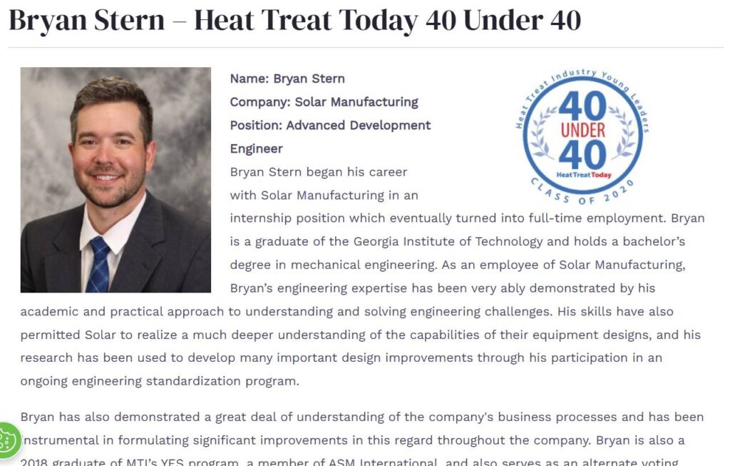
Click on the link to read more about Bryan Stern in his Heat Treat Today 40Under40 profile.
There are some good solutions out there. There are some bad solutions out there. And I think the higher possibility of getting into a bad solution with a less mature product is one of those obstacles people are facing. Things don’t change when forces are in equilibrium. So, the fact that we’re not changing as an industry to adopt some of this stuff just means that the forces motivating that change have not overcome the obstacles. There are definitely some obstacles to it.
And I’m sure we’ll get into talking about those some, but we have that nudge from regulation that’s happening. We’ll see, and continue to see, this type of product mature and those dynamic sealing mechanisms and transfer systems. And I think what’s really going to send it is that there are a lot of benefits that address a lot of problems that we’re all familiar with. It’s just not the de facto standard.
There are ways that the industry is organized around the methods that we use currently. A great example of that is the pizza example where you look at the back of the box of pizza, and you’ve got a recipe that says to preheat the oven and then pop it in for 15 minutes. If you can’t do that anymore, and you have to put the pizza in while the oven is cold and let it ramp up, now you have to change the recipe. And that’s the way we’re organized right now. We’re organized with processes for material that’s starting cold. It’s actually a harder way to do things, because the way that different equipment ramps up is harder to control. So, it’s not necessarily a better recipe, but it’s what we have.
The vacuum level specifications are another big impact. In single-chamber batch equipment, you’re exposing it to atmosphere every cycle, and you’ve got to pump it down quickly. So even when you pump it to very low vacuum levels, what’s left is still often oxidizing constituents.
If you can hold it at vacuum (even though it’s not getting to the same ultra-low pressures), and if it’s allowed to absorb from the surfaces and outgassing from materials (even at a higher pressure), you can have a pure environment. And that’s really counterintuitive. It’s not built into equipment specs because people associate the vacuum level with purity, and it’s really more about dew point and the constituents of what’s in the gas. You can have just as pure an environment with much higher pressure. And again, we’re just not organized around that right now.
Continuous and Non-Continuous Systems (00:21:56)
Doug Glenn: Let me restate something you said earlier and tell me if I’m accurate on it. You were saying that because of the single-chamber vacuum furnaces, we tend to increase the load sizes. So, I’m assuming the load size of the isolated heat furnaces could be significantly smaller and, therefore, have better uniformity within the load, both in the heat up and the quench. Is that an inherent advantage of the isolated heat?
Bryan Stern: It’s not specific to all isolated heat equipment. We’d have to get into discussing the fact that you can’t have continuous and non-continuous isolated heat systems. And it’s an important distinction. The distinction being that you have your heat chamber, you’re keeping it at temperature in a multi-chamber batch system, which is still a form of isolated heat equipment. You’re going to be moving your work in and out the same direction.
So, you’ll get a lot of the advantages that we’ve talked about. You’re able to have dedicated design for heating and cooling. You’ll have your thermal efficiency. There are a couple things you’re not going to get. You’re not going to be able to increase the throughput. Whereas, if you move to a continuous furnace where you’re moving that work in, and then you’re moving it to the other side . . . We can keep working with the pizza analogy: If you need more pizzas, and it takes 15 minutes for a pizza, you can move it through three stations for five minutes per station. Now, you’re getting a pizza every five minutes instead of every 15 minutes, right? If you’re able to do that and produce loads faster, then you can decrease the load size. And then you’re going to see all the benefits of decreasing that load size — improved uniformity, faster times, and better cooling.
Click on the image to read “Vacuum Heat Treating in a Carbon-Conscious Market” by Bryan Stern, in Heat Treat Today’s November 2023 Sustainability issue.
But you only get that if you go to continuous. With that specific type of isolated heat equipment, versus just any isolated heat equipment, you’ll get much better thermal efficiencies because in the multi-chamber batch setup you’re not heating and cooling the furnace every time and throwing that energy away. But because you’re loading and unloading on the same size, you’re still going to leave that heat chamber unoccupied, sitting and holding its temperature, consuming energy in between loads. With continuous furnaces, you’re not going to do that. You’re never going to throw all that energy away. There’s minimal holding power required. So, there is a distinction between the continuous and non-continuous isolated.
Doug Glenn: How would it work with a non-continuous isolated heat furnace? If the process required you to preheat, heat, and quench, what is it you’re going to use? Transfer cars? How does that work?
Bryan Stern: If you have multiple heating levels, you can still control the heat. But often you’d introduce it at an intermediate temperature and then ramp it up the rest of the way. So again, all the advantages that you get as far as quenching, typically with a two-chamber piece of equipment like that, your quench chamber is going to serve double duty as your evacuation chamber. You’re putting it into the quench chamber first, evacuating it again, and bringing it back and quenching it.
Challenges with Isolated Heat Systems (00:26:39)
Doug Glenn: These systems sound good, but I’m sure there are some challenges. Are there some drawbacks? I can hear some people saying, these sound like great pieces of equipment — especially the continuous version. I can understand the efficiencies, but what about the complexity? Is the design complexity of these units an issue?
Bryan Stern: It’s definitely one that I face a lot on the application side. It’s a much more complicated process — especially because the process itself is going to impact each of those positions. And you would care if I sold you an oven for your kitchen, and the only thing I cared about was that it can go to this temperature, and it can operate at this pressure, but I didn’t care what you did with it, I didn’t care how much work you get through it. I just had these maximum parameters.
As soon as you move to talking about continuous, you’re right away much more involved in throughput — going to drive and often the number of positions to get the index rate you need for the load size. Now you care how long each step of the process takes, and you’re trying to balance that among positions so that you’re not letting anything sit longer than it needs to because you’re over this particular soak time.
Trying to get continuous equipment sized for an application is more of a process than some people are expecting. And again, we’re just not wired that way. So, you can throw out a spec for a single-chamber batch furnace and say you need this operating temperature, this ultimate vacuum level, and this uniformity . . . and more! But when you come and want to get into a piece of equipment like this, we’re going to have a couple conversations — we’re going to talk about some things no one else is asking. And that’s what can be a hurdle up front, though we’re able to overcome it.
Bryan Stern, Gasbarre, discusses furnace cost effectiveness and flexibility. “It’s just going to be a lot more expensive if you’re doing a process that doesn’t require the way that that furnace was built. So, it’s not that you locked yourself in. It’s just that if you’re constantly changing processes or you have much shorter processes or the throughput isn’t a benefit, then that’s where a single-chamber batch might be a better solution.”
Doug Glenn: But it also may limit flexibility, I assume, of the different processes you could run in that equipment, too. In a batch system, you can put the load in there and do whatever you want, it’s going to potentially take longer to get it done. But maybe in an isolated heat system, where the heat chamer is only designed to do X, maybe you can’t do X times two. Does that make sense?
Bryan Stern: Yeah. It’s not as much true for a two-chamber or multi-chamber isolated heat batch style furnace because you have the same flexibility of dedicated design. On a continuous furnace, but if you’re going to be doing that a lot, is it worth paying for something that can be optimized one way if you’re going to be using it in a flexible way. They have a lot of flexibility — I would argue just as much as batch. It’s just going to be a lot more expensive if you’re doing a process that doesn’t require the way that that furnace was built. So, it’s not that you locked yourself in. It’s just that if you’re constantly changing processes or you have much shorter processes or the throughput isn’t a benefit, then that’s where a single-chamber batch might be a better solution.
Cost Effectiveness (00:30:23)
Doug Glenn: And then the other objection that jumps to my mind is capital equipment outlay. Can we address that, compared to single chamber?
Bryan Stern: This is this is another one that’s near and dear to my heart because I think there’s a lot of misconception here since it’s very application specific and hard to answer generally. But like we talked about, you’re going to have another chamber.
So, if you’re looking at a smaller system, it may not immediately be more cost effective. If you’re looking at a continuous system that’s replacing several furnaces, now you’re not paying for that oversized power supply on each piece of equipment; you’re not paying for a pumping system for each piece of equipment; you’re just buying it for the one evacuation chamber. Or maybe you have a backup, but now you’re starting to distribute and be much more selective about your material cost, and there’s definitely a break-even point in there.
It’s really a question of whether or not the process improvements are enough of a benefit on the smaller size. But very quickly the upfront cost starts to lean in favor of the continuous, especially if you’re looking at multiple pieces of equipment.
But the bigger thing here, the thing that I feel more passionate about, is that we tend to get really hung up on the upfront cost. And I think that’s something that can be very detrimental to missing out on value. It’s very easy to say: I’m going to have this amount of revenue, I’m going to pay this for equipment, and I’m not going to dive into maintenance and operating costs — and that’s a difficult question to answer but is a huge piece of the puzzle. Yet we often don’t put in the legwork because the information is not readily available. And it takes a more sophisticated accounting approach to look at project value over the life of the equipment.
Intuitively, we know that you could pay more for something that would improve efficiency or throughput or performance because in the long run that would pay off. And going back to the car analogy, when is the last time you bought a car and didn’t pay any attention to the fuel economy on it? It’s hard to do that without a little bit more accounting elegance.
Intuitively, we know that you could pay more for something that would improve efficiency or throughput or performance because in the long run that would pay off. And going back to the car analogy, when is the last time you bought a car and didn’t pay any attention to the fuel economy on it? It’s hard to do that without a little bit more accounting elegance.
Bryan Stern, Gasbarre
So, you have to look at the cash flow problem, do something like a net present value approach. And when you start looking at the operating cost savings, the efficiency improvements, and then a huge one that people miss is in the single-chamber batch furnaces we’re heating it up and down. That’s aggressive thermal shock and cycling. A lot of design goes into trying to get components to last because there’s thermal ratcheting and things wear out super quickly. For these continuous systems that are just sitting at temperature, that goes away for the most part.
They’re still consumable products, but the maintenance costs are dramatically improved, and you can talk to people who are using the systems. But again, that’s not something a lot of people have experienced, and it’s hard to quantify. So, if you just look at the upfront costs then it’s easy to miss out. You’re looking for an aggressive payback because you’re just hoping it’s going to cover the operating and maintenance expenses versus actually factoring those in and saying that those overall for the project life are going to increase value.
Limitations and Benefits of Isolated Heat (00:34:09)
Doug Glenn: That makes sense. Two final questions for you here: Are there any types of companies out there where it doesn’t make sense to use an isolated heat type system, whether it be a double chamber or continuous or whatever? And are you seeing, from the activity of , any industries that really should be looking at them?
Bryan Stern: Answering your first question with regards to the limitations, there are a couple situations where you’re not going to want to be looking at isolated heat.
One of those is really large parts. If an individual part is going to take up your whole work zone, then you’re not going to be able to decrease the load size and go to continuous and match the throughput. So, very large batch applications are going to be an obstacle; large parts are one area that it’s not going to shine. We’re seeing the 36” x 36” x 48” work zone is the practical cutoff. Another is the ability to use work TCs to monitor internal temperatures of the parts. That’s possible with continuous equipment. You can do a data pack and record temperatures, but it’s certainly not as convenient. So, when it comes to R&D, validating internal temperatures, and processes that require that, that’s another hurdle and limitation of this type of system.
The footprint is another one due to a second chamber for a batch style process is probably going to be larger in the space that it occupies because you’re not getting smaller in the work zone. So, it’s a question of whether you have the floor space, and do the other benefits of that system make up for the space it’s going to take up?
Doug Glenn: Those are good caveats. How about industries that you’re seeing who really should be adopting these things that either are or ought to be?
Bryan Stern: I don’t think it’s super industry specific, but there are some processes that benefit. And just a couple would be anything with a really short cycle time, because the dead time is going to consume more of the process.
If you can eliminate that and you only need to be at temperature for a little piece of time, then getting the rest of that dead time to be in parallel with the process to increase your throughput makes you a great candidate. But on the other hand, long processes are also a good candidate. If you’re holding it at temperature for a long period of time, boosting that efficiency while you’re in temperature, and better matching a power supply to what you’re doing.
So, good candidates could have short or long cycle times, involve any processes that require tight control, or benefit from isolating them from the space. Censoring can be a good candidate for rising carbon trading, where you can now actually have a dedicated space that maybe even operates at a higher vacuum level for whatever you’re trying to do, or you’re not worried about contaminating the parts with whatever process we’re running, or you need a tight time control. So, gas processes like that.
Oil quenching is an obvious candidate because you already have two chambers most of the time and isolating it, maintaining it at temperature, and keeping it clean from any oil vapors makes it a great example.
For anything with expensive parts, you can minimize the risk by decreasing the load size instead of having a many thousand-pound load where if something goes wrong, you’ve lost it. And especially for applications where that can be a really expensive thing if something goes wrong, you’d rather have it go wrong with much less material at risk.
Doug Glenn: I would think traceability is also probably easier in one sense. With this isolated heat system; you don’t have a huge batch in there. You’re processing potentially smaller batches, and you’re able to isolate which batches are at what temperature or what kind of quench they go through. Those may be some advantages.
Bryan Stern: You had a very specific application for a client who was concerned with a lot of small parts and traceability down to each part, and we’re looking at that system. Anytime you have a high volume of work, if you’re looking at multiple batch, single-chamber batch furnaces to meet throughput, that’s one of the biggest indicators you really should probably be looking, or at least considering, these other systems. And any time you have a lot of small parts in baskets, a large single-chamber batch furnace with stacked baskets of tiny parts, you’ll probably have a lot of benefit.
Doug Glenn: I assume that if somebody is looking at purchasing multiple single-chamber furnaces, you guys would have some sort of a calculator to help them assess if it makes sense financially and process-wise to go with six batch furnaces or one continuous. Is that a safe assumption?
Bryan Stern: Yeah, that’s one of my favorite parts of the process is to take a specific application, go through and break it down, and put together that full project ROI where you’re actually starting to assemble what are we looking at for maintenance costs? What is it going to cost to operate? And now you’re starting to see at a project level, not just the upfront cost, which option is going to be best. And it is so application specific. It’s kind of neat to walk through that with a client and see what comes out the other end. Because at the end of the day, you want what the best solution is. It could be this or that. But when you can actually put that picture together for a process and assist someone with picking the best equipment for what they need for their process, that’s fun.
Doug Glenn: And just for the listener’s benefit, because we haven’t done a lot of talking about your company Gasbarre Thermal Processing Systems. You guys can provide either the isolated heat systems or, if you do the calculations on your handy dandy spreadsheet and it turns out they’re better doing the standard single chamber, you guys can do those, too. So, it’s not like you’re going to push one over the other but whatever makes sense. Right?
Bryan Stern: I see that as a huge advantage. You’re not going to get a bias of us at Gasbarre trying to push you into this because it is what we’re selling. We are able to wade through that decision with the client and help pick the equipment that’s best for them.
Doug Glenn: Helping them make a better choice, super, Bryan. Thank you.
About the Expert
Bryan Stern is the product development manager at Gasbarre Thermal Processing Systems. He has been involved in the development of vacuum furnace systems for the past 8 years and is passionate about technical education and bringing value to the end-user. Bryan holds a B.S. in Mechanical Engineering from Georgia Institute of Technology and a B.A. in Natural Science from Covenant College. In addition to being a member of ASM, ASME, and a former committee member for NFPA, Bryan is a graduate of the MTI YES program and recognized in Heat Treat Today’s40 Under 40 Class of 2020.