Heat Treat Radio #111: Heat Treat NextGen Brynna Keelin Kelly-McGrath
If curiosity were a person, Brynna Keelin Kelly-McGrath would be her name. Having risen at Moog, Inc. to the position of materials and process engineer, Brynna shares her early STEM interests and how she stays up-to-date on industry trends and ideas. In this highly engaging NextGen profile on Heat Treat Radio — with host and Heat Treat Today’s publisher, Doug Glenn — get to know this talented metallurgist.
Below, you can watch the video, listen to the podcast by clicking on the audio play button, or read an edited transcript.


The following transcript has been edited for your reading enjoyment.
Meet Brynna Keelin Kelly-McGrath (01:00)
Doug Glenn: Let’s jump into today’s Heat Treat Radio episode with Brynna Keelin Kelly-McGrath from Moog, Inc. It’s a great pleasure to be here today with Brynna, who is one of our 40 Under 40 Class of 2023 award recipients. First off, congratulations on that award, and welcome to Heat Treat Radio.
Brynna Keelin Kelly-McGrath: Thank you so much. That was an honor.
Doug Glenn: Brynna lives just south of Buffalo, New York. As you know, this interview is to get to know you a little bit more — how you got into metallurgy, heat treating, and all that good stuff. Let’s start way back. Give us a little bit about yourself as a younger person, maybe high school age and moving on up through, and then how you got involved with heat treating and metallurgy.
Brynna Keelin Kelly-McGrath: Sure. I grew up in a little town called West Falls, south of Buffalo, New York, and about 20 minutes from Moog. While I was in high school, I took AP chemistry and physics and fell in love with those topics. I knew from a younger age that I was going to wind up being an engineer eventually; I just didn’t know what kind. But I was pretty sure I wanted to be a chemical engineer, so I toured a couple of colleges.
At one of them, I met with a materials science professor to talk about the differences between chemical and materials science engineering. I was sold. I was all set and ready to go be a polymers engineer. I picked Purdue University, started going there, and was absolutely loving it.
The summer after my freshman year, I got an internship with Moog, which was right around the corner from my hometown. The internship was primarily metallurgical, due to the nature of Moog’s products, and I absolutely loved it. I was not expecting to like it, and it was just so great. So, I transitioned all of my coursework over to metallurgy, and I kept coming back to Moog for internships, and that was fantastic.
Learning from Industry Experts (03:32)
When I started off at Moog, it was right around the time when two of our subject matter experts in heat treatment were transitioning to retirement. I started learning as much as I could as fast as I could about heat treatment. There was obviously a lot to learn there, but it was a great time.
After working at Moog for a couple of years, I decided I wanted to go back and pursue my other passion, which was manufacturing engineering. So, right now I’m working on a master’s degree after work to combine metallurgy and manufacturing.
“When I started off at Moog, it was right around the time when two of our subject matter experts in heat treatment were transitioning to retirement. I started learning as much as I could as fast as I could about heat treatment.”
Brynna Keelin Kelly-McGrath, Moog
Doug Glenn: Wow. You’re a classic overachiever. That’s pretty good. And you said Purdue, correct?
Brynna Keelin Kelly-McGrath: Yeah.
Doug Glenn: Okay. And you did your undergrad there. Did you actually end up graduating with a materials engineering degree or a metallurgy degree?
Brynna Keelin Kelly-McGrath: Materials science and engineering.
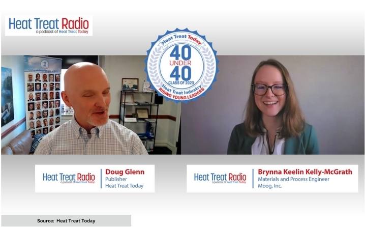
Source: Heat Treat Today
Doug Glenn: All right. Good. You spent the summers back at Moog and enjoyed that. You know, we see a lot of the older generation retiring, so you’re filling the brain drain, as we say, which is great. Are there are many other young people at Moog?
Brynna Keelin Kelly-McGrath: Yeah, their internship co-op program has been fantastic in bringing in a lot of students right out of college and getting them hooked on our product line and the sort of manufacturing we do. And we’re definitely getting more recent college graduates. But, you know, with people retiring, those are some awfully big shoes to fill.
Doug Glenn: For sure. What exactly does Moog make at your facility? They’re a large corporation; I know they usually make a lot of automotive, maybe aerospace, components but are you able to say specifically what Moog does there?
Brynna Keelin Kelly-McGrath: We specialize in high precision motion actuation systems. From a metallurgical side, we’re working with a ton of really cool materials. So it’s not just steels or aluminum, it is a lot of aerospace applications, defense. The materials and process engineering group is physically orchestrated on our headquarters campus as well as the space and defense building, so we do get to see quite a bit of that. From the metallurgical perspective, there is a lot to see and work on.
Doug Glenn: You mentioned you were thinking about being a chemical engineer, but then you saw the materials. Do you remember what it was about that and metallurgy that attracted you? Anything specific?
Brynna Keelin Kelly-McGrath: I remember sitting through that talk with a materials professor at Purdue, and he was talking about what the day to day of a chemical engineer versus materials engineer looks like. I will not pretend that he wasn’t biased, because he was a materials professor. But the work he described for materials engineering was so diverse, and there were options for different settings and what you could end up working on — from being in a steel mill to working in a lab like I do. There are a lot of options, a lot of cool things. The slogan at Purdue was something along the lines of: you can’t make it without materials.
Brynna’s Family Background (07:30)
Doug Glenn: That’s really neat. So, I haven’t asked you about your family at all. What did they think when you told them, hey, I’m thinking about being a materials engineer or a metallurgist?
Brynna Keelin Kelly-McGrath: My father is an industrial engineer, and my mother is a pharmacometrician, so they’re both in the stem field already. I think it was no surprise that I was going to pursue engineering and then, metallurgical engineering specifically. I think they were happy to encourage me to pursue any of my passions. And my father knew a couple of materials engineers and thought that it would work out for me. They were excited.
Undergraduate Research (08:16)
Doug Glenn: They were very supportive. That’s great. When you did your undergrad at Purdue, did you have to work on a final paper or any specific projects that were of interest to you?
Brynna Keelin Kelly-McGrath: I did some undergraduate research in the metallurgy realm. But my senior project for graduation was along the lines of characterizing shot for shot peening and the degradation of shot and the residual stress that it imparts. It was like a cool mix of FEA modeling with actually characterizing the material. It was a neat project.
Doug Glenn: Have you had to do any of that at Moog?
Brynna Keelin Kelly-McGrath: There’s a fair deal of materials characterization. We have shot peening, but I’m not super involved with it.
Current Work at Moog (09:35)
Doug Glenn: Gotcha. That’s interesting. Can you describe what your typical day at Moog looks like now and what you’re working on?
Brynna Keelin Kelly-McGrath: Sure. My typical day is a good deal of talking with all types of engineers, explaining metallurgical concepts. Because we work on a lot of different materials, there’s a lot to understand there. A good portion of my role is talking with other engineers about how a heat treatment procedure works or what’s metallurgically happening, how to modify a manufacturing sequence, how to design so that the product’s going to work.
But then I also specifically work in a failure analysis lab. This could be anything from something’s coming off the manufacturing line a little bit wrong or something failed in the field. We’ve got a beautiful characterization lab full of all the toys that you could think of, including two SEMs and a chemical lab. There’s a good deal of analysis there, too.
Doug Glenn: You seem like a person who enjoys your work. Is there any specific story or instance of something happening, either in school or at work, that really made you happy that you were in metallurgy and heat treat?
Brynna Keelin Kelly-McGrath: Oh, goodness. That’s a good question.
I would have to say I’ve had a couple projects at work, without getting into too many specifics, where we discovered something new metallurgically that we didn’t know was happening before. And then working through that, how did we not know it before? What do we know about it now? And what are we going to do to utilize this new thing that we discovered and take advantage of it? From a heat treat perspective, sometimes that means modifying our procedures, modifying our fixturing, creating something new.
It’s neat to see the modifications happen and come up with the new parts on the other end. It’s been very exciting to work on interdisciplinary teams like that.
Source: Heat Treat Today
Doug Glenn: Yeah. I’m curious about this. You’ve been out in the work world for how many years?
Brynna Keelin Kelly-McGrath: Three and a half.
Doug Glenn: Okay. So, you’ve been out of school and working four years, and the amount you know about metallurgy and heat treating now is four years’ worth. Does it kind of amaze you the amount of stuff we don’t know?
Brynna Keelin Kelly-McGrath: Absolutely. Metallurgy is an old science, but you know we’re still [developing] the tools and technology and it’s great to find out new things.
Doug Glenn: Right. A lot of people get involved and say, “Well, I don’t want to go into metallurgy and heat treat because it’s a mature industry,” but I was curious if you felt the same way.
It’s really quite fascinating because there is a lot that happens. Like you were saying at Moog when you discovered things, a lot of stuff that’s happening and we really don’t know why. The more we can discover about it, the better.
Brynna Keelin Kelly-McGrath: Absolutely.
Top Industry Resources (12:58)
Doug Glenn: Let me ask you this. You obviously come from a smart family; you’ve got parents who are well educated, and you are as well. What are some of the metallurgical/heat treat resources that you use to stay current?
Brynna Keelin Kelly-McGrath: I think the best resource that’s out there is people. The network that I’ve been growing comes from a variety of different sources. I’m part of a few industrial committees, and it’s just a great way to meet people from all ends of the spectrum of metallurgy — from those producing the material to those making something out of it to the people who are going to use it all the way down the line.
Finding other metallurgists in those realms, and also through venues like ASM and our local Buffalo chapter — meeting people who have more experience than I do and have seen it before. If I’m seeing something for the first time, there’s definitely someone who spent their whole career on that. It’s really great to tap into those resources. That’s my number one.
And then my second choice would be the ASM handbooks. I’ve always got at least two open on my desk.
“I think the best resource that’s out there is people.”
Brynna Keelin Kelly-McGrath, Moog
Doug Glenn: Those are great resources. ASM over the years has pumped out some very, very good stuff. Is there anything else about your work or your schooling that is of interest or excited you that you’d like to share?
Brynna Keelin Kelly-McGrath: I really liked working at Moog because it’s a cool application where I can use my metallurgical knowledge along with this new manufacturing knowledge that I’m building up. That was my favorite intersection with my undergrad degree. And now I get to actually try that out in a working sense. That’s been great.
Doug Glenn: And you’re doing a master’s in industrial engineering?
Brynna Keelin Kelly-McGrath: Manufacturing engineering.
Doug Glenn: Where are you doing that?
Brynna Keelin Kelly-McGrath: The University of Michigan.
Doug Glenn: Remotely, I’m assuming?
Brynna Keelin Kelly-McGrath: Yes.
Doug Glenn: Very nice. And how far along are you, and how much longer do you have to go there?
Brynna Keelin Kelly-McGrath: I’m hoping to graduate in December, so I’m coming closer to the finish line.
Doug Glenn: Congratulations. That’s really good.
Rapid-Fire Round (15:44)
Doug Glenn: I want to move off of metallurgy and heat treat just to learn a little bit more about Brynna. All right, so these quick questions are what I call the rapid-fire round. Brace yourself. Are you a Mac or a PC person?

Brynna Keelin Kelly-McGrath: I am a Mac person through and through. I love my Mac.
Doug Glenn: Do you use a Mac at work?
Brynna Keelin Kelly-McGrath: I wish, but no.
Doug Glenn: We have an ongoing debate here. We had a couple people that came into the organization with Macs, and I’ve always been a PC guy. So, anytime there’s a computer problem, we tease each other, “Well, that’s because you’re working on a Mac/you’re working on a PC.” Well, that’s good to know. And for your phone: Are you an Apple phone person?
Brynna Keelin Kelly-McGrath: Yeah, I’ve got an iPad. And I just got a new MacBook Air the other day.
Doug Glenn: You’re hardcore. Very good.
So, we’re a publishing company here at Heat Treat Today. And I like to ask this question: When you consume media, do you prefer hard copy or digital?
Brynna Keelin Kelly-McGrath: I prefer digital. I like to have all of my work life very organized by topic, and it’s way easier for me to organize everything if I have a digital copy of it. So even if it’s a print copy, I’ve been known to scan and file it the way that I file everything else.
Doug Glenn: Okay. Now what do you value more in work — a flexible work schedule or high pay?
Brynna Keelin Kelly-McGrath: I’m going to go with flexible work schedule. I’ve had some people close to me who have the high pay but no flexibility. And they’re the ones more jealous, so I’m going to go with that. I’ll take the flexibility.
Doug Glenn: That’s a great answer. Here’s one: Would you rather work remotely or in an office?
Brynna Keelin Kelly-McGrath: In an office 100%, I am definitely of the variety that likes to be around people. I would rather have people to talk to face to face than doing it over Teams.
Doug Glenn: I kind of assumed you were like that. How did you handle all the isolation that came with the recent pandemic?
Brynna Keelin Kelly-McGrath: I was still in college at that time for most of Covid. Purdue was only remote for half of one semester. It was a reasonably short time. And then the rest of the time we had limited capacity in classrooms and things. But when I was coming back for my internships, our department was classified as essential. We were coming into the office every day, and that was good, I enjoyed that.
Doug Glenn: So, you didn’t necessarily really have a lot of the isolation or as much as you might have had.
Brynna Keelin Kelly-McGrath: Yep.
Doug Glenn: That’s good. Okay, I won’t keep going down that road. I think that whole time period has been very impactful on our society. And I’m curious how people feel it has affected them.
I know you love working at Moog, but if you had a dream job, what would it be?
Brynna Keelin Kelly-McGrath: I don’t know. I think someday down the line, it would be cool to have my own manufacturing business. I don’t have a product in mind at the moment, but in my thoughts it has to do with metallic components and heat treatment, because that’s my passion. That would be great.
Doug Glenn: Very interesting, owning your own company and manufacturing something metal. You know what? That’s where it starts. You’re three and a half years out, and you’ve got time to develop more specificity over time. But that’s good to even know that you’re moving in that direction.
I assume you don’t work all the time. What do you do? What do you do in your free time? What do you like? What are your passions outside of work?
Brynna Keelin Kelly-McGrath: The number one time consumer at the moment is that master’s degree. But then, you know, on a pure fun basis, my husband and I are avid golfers. And all of the very short Buffalo summer we’re trying to be out there on the golf course.

Source: Richard-7 / Getty Images Signature
Brynna Keelin Kelly-McGrath: I’m also a bluegrass fiddler. I play in a couple bands. And that’s pretty fun, too. It’s almost Saint Patrick’s Day.
Doug Glenn: You’re a musician? You know, I’ve heard that there are some engineering schools who don’t ask you if you play an instrument, they ask you what instrument you play because there is a correlation somehow or other between music and engineering. Maybe it’s the methodical-ness, the orderliness, and all that stuff.
Brynna Keelin Kelly-McGrath: Neat, I didn’t know that.
Doug Glenn: If you’re playing bluegrass fiddle, I assume you play some by ear. I mean, I assume you’ve got some sort of natural talent there. Is that safe to say?
Brynna Keelin Kelly-McGrath: Yeah, I started that at a decently young age. And now my husband and I are learning piano as well, so it’s been fun.
Doug Glenn: What does your husband do by chance?
Brynna Keelin Kelly-McGrath: He’s a software engineer.
Doug Glenn: Two engineers in one house. That’s got to be interesting dinner time talk. That’s wonderful.
Okay. Last question for you. I give people an option here. You can answer any one of these three. What would be your favorite app, movie, or magazine?
Brynna Keelin Kelly-McGrath: The first thing that came to my mind when you asked that question was Audible. At the moment, I’m hooked on reading, or listening, to a lot of books. I consider it reading in the little bits of downtime here and there grocery shopping and driving in the car and things like that. It’s nice to spend that time a little bit more productively.
Doug Glenn: I’m with you. I think that’s great. I assume maybe you can even do some of your school reading on Audible?
Brynna Keelin Kelly-McGrath: I haven’t tried that yet. Honestly.
Doug Glenn: Sometimes people learn better by actually reading. But other people learn better by listening, so that’s fine.
If you were to encourage young people to really look into metallurgy materials, what would you tell them? What would be your encouragement to them?
Brynna Keelin Kelly-McGrath: I think the most impactful thing for me at that age was actually getting to see what they do. At Moog, I act as a tour guide for a lot of high school students. I try to show them as closely as possible what we do and what a day looks like. Because it’s great to think about the theory, but at the end of the day when you graduate with that degree, you’ve got to go work. I encourage high school students to get out there and see as many jobs as possible. Shadow people — I guess that would be my advice.
Doug Glenn: That’s good. Well, Brynna, thanks so much. Congratulations again on being awarded 40 Under 40 this last year. And thanks for taking some time to chat with us.
Brynna Keelin Kelly-McGrath: Thank you so much.
About The Guest

Materials and Process Engineer
Moog, Inc.
Source: Brynna Keelin Kelly-McGrath
Brynna Keelin Kelly-McGrath received her bachelor’s degree in Materials Science and Engineering from the Purdue University Honors College. She is currently working on a master’s degree in Manufacturing Engineering from the University of Michigan Ann Arbor. Brynna conducts metallurgical support for day-to-day heat tree issues and non-conformances across several divisions within Moog, Inc. She was recognized in Heat Treat Today’s 40 Under 40 Class of 2023.
Contact Brynna by visiting Moog, Inc.’s website: www.moog.com.
Search Heat Treat Equipment And Service Providers On Heat Treat Buyers Guide.Com
Heat Treat Radio #111: Heat Treat NextGen Brynna Keelin Kelly-McGrath Read More »