Reliable induction heat treating depends on more than metallurgy — it requires precise, repeatable performance from every part of the induction system. In this Technical Tuesday installment, Aaron Goodwin, business development engineer for Inductoheat, explores how induction coils, power supplies, quench systems, and real-time process monitoring work together to consistently achieve the hardness, case depth, and microstructure demanded by today’s automotive components. Learn how equipment reliability, preventive maintenance, and process control help manufacturers reduce variability, improve quality, and keep production running efficiently.
This informative piece was first released in Heat Treat Today’sAugust 2026 Annual Automotive Heat Treating print edition.
There is a critical partnership between an automotive component’s design and its heat treat requirement. In modern vehicle manufacturing — whether trucks, SUVs, or crossovers — the margin for error is very small. Components like axles, gears, shafts, and other engine/drivetrain elements are subjected to demanding loads, high torque, and complex operating conditions. These vehicles must balance durability, efficiency, quiet operation, and performance. They also need to successfully handle a wide range of driving scenarios, from stop-and-go urban traffic to towing, off-road use, and long-distance travel.
Across these vehicle platforms, one reality remains constant. While material selection and engineering design are critical, consistency and reliability of the heat treating process determine whether components perform as intended in real-world conditions. Induction heating for case hardening of automotive components is a common choice among design engineers, and reliable induction heating equipment is key.
From the induction coil to the power supply and the quench system, each must operate with precision and repeatability for every cycle. Induction case hardening depends on tightly controlled variables working in harmony. When performance is stable, quality heat treated components follow. When it is not, variability is introduced and with it risk.
The Link Between Induction Equipment and Metallurgy
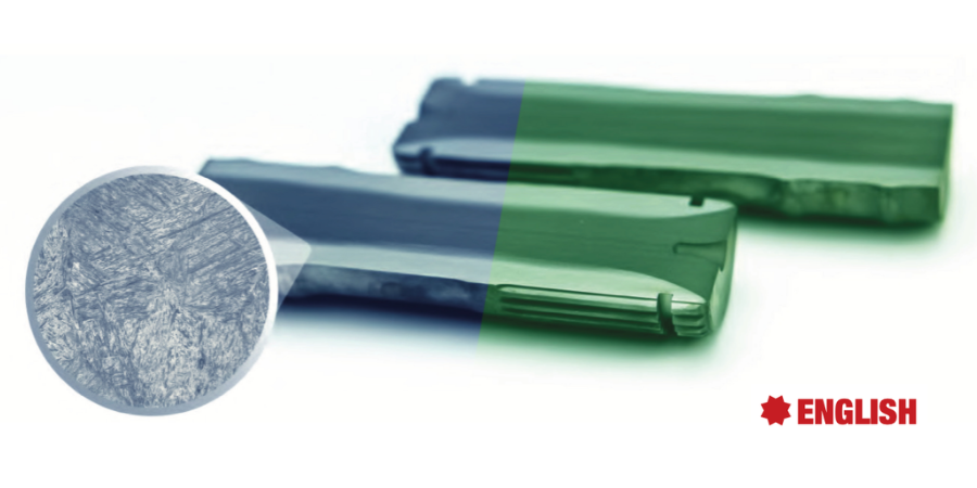
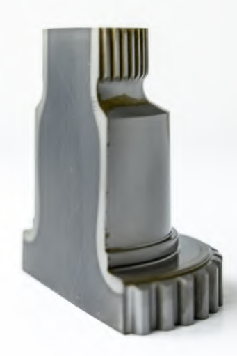
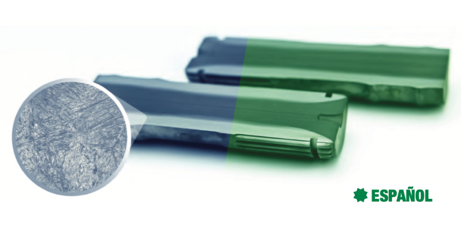
Sectioned and etched case-hardened shaft with large splines | Image Credit: Inductoheat
Heat treated components are evaluated based on hardness, case depth, and microstructure of the steel after processing. Each component has a heat treat specification that defines these metrics. Some components require shallow case depths while others have very deep case. Shallow case is needed for surface wear resistance, while deep case is specified for strength under high torsional loads, and there are scenarios in between.
Induction heat treatment equipment reliably executes several tightly controlled variables to produce the required metallurgical properties. Key variables include power output and frequency, heating time, coil geometry and position, quench timing, and flow rates.
Each variable plays a critical role: even small deviations can significantly alter results. A slight fluctuation in power delivery, for example, may reduce case depth or create uneven hardness profiles. In truck components, this could result in reduced fatigue life under high loads. In a crossover or SUV, it may show up as premature wear or component failure. Reliable equipment ensures that these variables remain tightly controlled cycle after cycle, part after part. It transforms heat treating from a “variable process” into a repeatable, engineered system.
The Role of Induction Coil
The induction coil is where the energy meets the automotive component. Its design and condition directly influence heating and resulting hardness case patterns. A well-designed and properly maintained coil provides consistent electromagnetic coupling, uniform heat distribution along the surface, and sufficient penetration sub-surface for creating required case depths and hardness profiles.
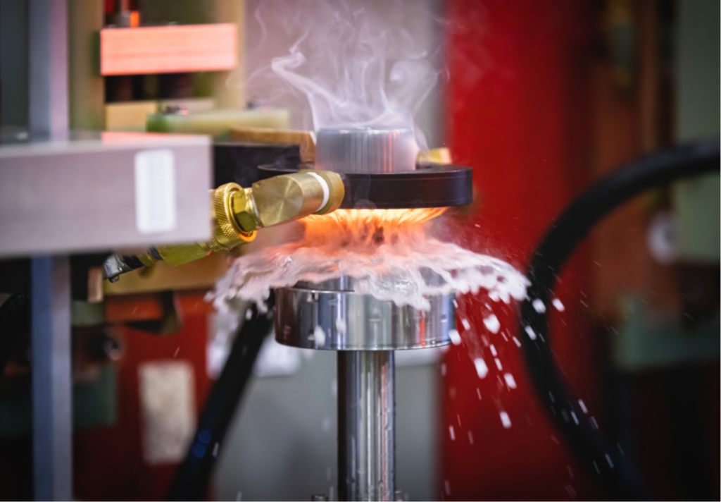
When energized, the induction coil produces a magnetic field. From this, the automotive component begins to experience Joule heating from induced current, known as eddy currents. Heat times vary but are often only a few seconds in duration to reach the temperature required for the formation of austenite (range of 750–850°C [1382–1562°F], depending on chemical composition of steel).
Induction scan coil with integrated spray quench for case hardening | Image Credit: Inductoheat
Induction coils are perishable tooling components. Over time, thermal cycling, surface oxidation, and degradation, along with mechanical fatigue can reduce performance. Minor changes in coil geometry, alignment, or surface conditions can alter the electromagnetic field and introduce variability. What makes this especially challenging is that these changes are often gradual and not immediately visible. A coil may continue operating while quietly affecting heat distribution. Routine inspection, cleaning, and scheduled replacement are essential. In high-volume automotive manufacturing, proactive coil management is critical to maintaining process stability and reliably heat treated components.
Power Supply Stability
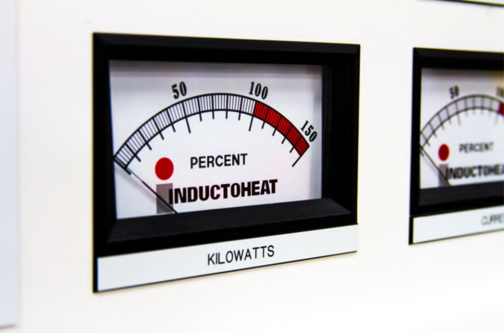
The induction power supply governs how energy is delivered to the coil and thus the component being heat treated. A stable output of power is critical for repeatable heating and consistent metallurgical results. Selection of the proper output frequency is important to balance the required depth of heating and the surface temperature of the component. For case hardening, the most common frequencies utilized fall in the range of 1,000 Hz up to 200 kHz. While a single power supply cannot cover this entire frequency range, most will provide some range of frequency flexibility.
Power supplies have precise and programable energy delivery at a stable frequency. They provide rapid response to variations in load as the temperature of the automotive component increases, passes through the curie point, and reaches the target temperature. This power supply gives reliable performance across long production runs. This is important when thousands of components must meet specifications in a narrow margin of variability. If a power supply introduces fluctuations, these will affect the heating rates and final hardened properties. For manufacturers, this leads to scrap parts and reduced profitability.
Power supply analog meter, % power–kilotwatts | Image Credit: Inductoheat
These work horses need scheduled maintenance. After all, reliable power delivery directly supports both quality and productivity. Personnel must:
Periodically check the power supply for tight electrical connections on bus work and wire terminals.
Check all cooling water hosing connections for tightness as the hoses age.
Verify that all protection switches are working.
Ensure that the cooling system’s water is clean and check its conductivity monthly.
Refer to the manufacturer’s manual for more information.
Quenching: Completing the Process
Heating is only half of the equation. The quenching process is initiated after the component has reached its austenitizing temperature at the desired depth. Quench fluid is sprayed uniformly onto the surface of the component, which removes heat in a rapid and controlled manner. This produces the formation of martensite giving the automotive component a case-hardened surface layer. All of this is done within proper limit set points to produce repeatable heat treated components.
Quench fluid is typically water with polymer additive. It needs to be maintained at the appropriate temperature and with the required percentage of polymer quench additive. The quench system delivers it with precise timing relative to heating. The pump and valves must provide consistent flow rates and pressures. The heat exchanger in the quench system will remove excess heat from the quench fluid. Otherwise, the temperature of the fluid will continue rising after each cycle.
Over time, quench water evaporates raising the concentration of polymer quench. It also becomes contaminated with oily residue, metal chips, and more. Quench system bag filters become full, and the many orifices of quench spray devices get clogged with scale and debris. The quench system needs to be maintained to ensure that cooling is controlled and repeatable. This completes the heat treating process with consistency and reliability.
Data-Driven Reliability
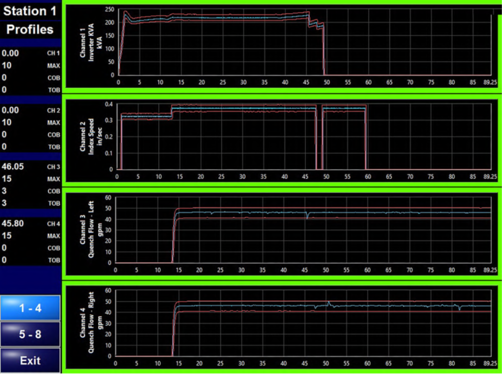
Induction equipment must function with precision to achieve the required heat treatment. When this equipment includes real-time monitoring and data collection during the process, further confidence is provided. Signature monitoring measures the many aspects of induction heat treatment for every cycle. This “signature” can record electrical parameters like inverter power, current, voltage, and frequency over the process time. It can also include quench fluid temperature, flow, and pressure, along with machine scan speed and spindle rotation speed. Each of these is given a percentage of permitted variation, graphed over time. Any deviation outside of these boundaries during the cycle, and the machine will initiate a process fault.
Inductoheat QAS process signature with high/low boundaries; graphing interverter KVA scan speed, quench flow-left spindle, quench slow-right spindle | Image Credit: Inductoheat
This can be an important part of a quality assurance system (QAS) and ensure confidence during each production shift. For automotive components with barcodes or other unique markings, traceability becomes possible, saving the process signature from the machine and assigning it to the heat treated component. This step can provide critical data to isolate a batch of parts should the need arise, avoiding the tendency to quarantine more pieces than necessary.
Across the full spectrum of vehicle manufacturing, from heavy-duty trucks to everyday SUVs and crossovers, performance is built layer by layer. As vehicle platforms continue to evolve, heat treating processes must keep pace with increasingly complex component designs and performance requirements. Reliable induction equipment is essential to meet these challenges. Each aspect must operate with precision and consistency. Routine maintenance, including the replacement of wear items such as induction coils, helps ensure process stability, consistent results, and dependable production.
For many manufacturers, maintaining reliability also means modernizing existing equipment. Aging induction systems can often be rebuilt with updated controls, power supplies, and critical components, extending service life while improving performance and uptime. They can also be re-tooled for new heat treat programs.
By investing in induction equipment, manufacturers can continue producing high-quality components that support the demands of today’s vehicles.
About The Author:
Aaron Goodwin Business Development Engineer Inductoheat
Aaron Goodwin has over 32 years of experience in the induction heating industry, having held a variety of technical positions with Inductoheat in Madison Heights, Michigan. In his current role as business development engineer, Aaron provides technical support to both sales and engineering, with responsibilities that include leading the finite element analysis (FEA) simulation team for coil and process design. Aaron also collaborates with global sister companies throughout the Inductotherm Group, supporting technology development, knowledge sharing, and customer-focused solutions worldwide.
Un tratamiento térmico por inducción fiable depende de algo más que la metalurgia: requiere un desempeño preciso y repetible de cada parte del sistema de inducción. En este artículo, Heat TreatTodayAaron Goodwin, ingeniero de desarrollo de negocios de Inductoheat, explora cómo las bobinas de inducción, las fuentes de alimentación, los sistemas de temple y el monitoreo del proceso en tiempo real trabajan en conjunto para lograr de manera consistente la dureza, la profundidad de capa y la microestructura que demandan los componentes automotrices actuales. Conozca cómo la confiabilidad del equipo, el mantenimiento preventivo y el control del proceso ayudan a los fabricantes a reducir la variabilidad, mejorar la calidad y mantener la producción funcionando eficientemente.
Este artículo informativo se publicó por primera vez enHeat Treat Today’sAugust 2026 Annual Automotive Heat Treating print edition.
Existe una relación fundamental entre el diseño de un componente automotriz y los requisitos de su tratamiento térmico. En la fabricación moderna de vehículos ya sean camiones, SUVs o crossovers, el margen de error es extremadamente reducido. Componentes como ejes, engranes, flechas de transmisión y otros elementos del motor y del tren motriz, están sometidos a elevadas cargas, altos niveles de torque y condiciones de operación cada vez más exigentes. Estos vehículos deben ofrecer un equilibrio entre durabilidad, eficiencia, operación silenciosa y desempeño. Además, deben responder de manera confiable a una amplia variedad de escenarios de conducción, desde el tráfico urbano con constantes arranques y paradas, hasta el remolque de cargas, la conducción todoterreno y los recorridos de larga distancia.
Independientemente del tipo de vehículo, existe una constante. Si bien la selección del material y el diseño de ingeniería son fundamentales, la consistencia y confiabilidad del tratamiento térmico son las que determinan si un componente cumplirá con el desempeño esperado en condiciones reales de servicio. El calentamiento por inducción para el endurecimiento superficial de componentes automotrices es una de las tecnologías preferidas por los ingenieros de diseño, y contar con equipos fiables de calentamiento por inducción es fundamental.
Desde la bobina de inducción hasta la fuente de potencia y el sistema de temple, cada elemento debe operar con precisión y repetibilidad en cada ciclo de producción. El endurecimiento superficial por inducción depende de un conjunto de variables estrictamente controladas que deben trabajar de manera sincronizada. Cuando el proceso permanece estable, se obtienen componentes tratados térmicamente de calidad; cuando esto no ocurre, surge la variabilidad y, con ella el riesgo.
La Relación entre el Equipo de Inducción y la Metalurgia
Los componentes tratados térmicamente se evalúan principalmente por tres características: la dureza, la profundidad de capa endurecida y la microestructura del acero después del procesamiento. Cada componente cuenta con una especificación de tratamiento térmico que define estos parámetros. Algunos componentes requieren capas endurecidas poco profundas para maximizar la resistencia al desgaste superficial, mientras que otras demandan capas mucho más profundas para soportar elevadas cargas de torsión; también existen situaciones intermedias.
Eje cementado, seccionado y atacado químicamente, mostrando estrías de gran tamaño | Crédito de la imagen: Inductoheat
Los equipos de tratamiento térmico por inducción controlan de manera confiable diversos parámetros críticos para producir las propiedades metalúrgicas requeridas. Entre las más importantes se encuentran, la potencia suministrada y la frecuencia, el tiempo de calentamiento, la geometría y posición de bobina de inducción, sincronización, y el caudal del sistema de enfriamiento.
Cada una de estas variables desempeña un papel fundamental; incluso pequeñas desviaciones pueden modificar significativamente los resultados obtenidos. Por ejemplo, una ligera fluctuación en la potencia suministrada puede disminuir la profundidad de capa endurecida o generar perfiles de dureza no uniformes. En componentes para camiones, esto puede traducirse en una menor vida útil a fatiga bajo cargas elevadas. En vehículos tipo SUV o crossover, puede manifestarse como desgaste prematuro o incluso la falla del componente. Los equipos confiables garantizan que todas estas variables permanezcan estrictamente controladas ciclo tras ciclo y pieza tras pieza. De esta manera, el tratamiento térmico deja de ser un proceso susceptible a variaciones y se convierte en un proceso de manufactura repetible y controlado.
El Rol de la Bobina de Inducción
La bobina de inducción es el punto donde la energía interactúa directamente con el componente automotriz. Su diseño y estado de conservación influyen de manera directa en el calentamiento y, en consecuencia, en el patrón de endurecimiento obtenido. Una bobina correctamente diseñada y con un mantenimiento adecuado proporciona un acoplamiento electromagnético uniforme, una distribución uniforme del calor sobre la superficie y una penetración subsuperficial suficiente, permitiendo alcanzar la profundidad de capa endurecida y el perfil de dureza especificados.
Al recibir energía, la bobina de inducción genera un campo magnético. Esto provoca que el componente automotriz experimente un calentamiento por efecto Joule debido a la corriente inducida, fenómeno conocido como corrientes de Eddy. Los tiempos de calentamiento varían, generalmente basta unos pocos segundos para alcanzar la temperatura necesaria para la formación de austenita (rango de 750 a 850°C [1382–1562°F] dependiendo de la composición del acero).
Bobina de inducción con sistema de enfriamiento por rociado integrado para el endurecimiento superficial | Crédito de la imagen: Inductoheat
Las bobinas de inducción son componentes de herramiental sujetos a desgaste. Con el tiempo, los ciclos térmicos repetitivos, la oxidación superficial, el desgaste y la fatiga mecánica reducen gradualmente su desempeño. Pequeñas modificaciones en la geometría de la bobina, su alineación o sus condiciones superficiales pueden alterar el campo electromagnético e introducir variabilidad. Lo más complejo es que estos cambios suelen producirse de forma gradual y no resultan visibles de inmediato. Una bobina puede continuar funcionando mientras afecta la distribución del calor sin que el problema sea evidente. Inspecciones periódicas, la limpieza y el reemplazo programado de las bobinas son fundamentales. En la manufactura automotriz de alto volumen, una gestión proactiva de las bobinas es esencial para mantener la estabilidad del proceso y garantizar la fiabilidad de los componentes tratados térmicamente.
Estabilidad de la Fuente de Alimentación
La fuente de alimentación del sistema de inducción controla la forma en que la energía se suministra a la bobina y, por lo tanto, al componente que será tratado térmicamente. Una salida de potencia estable es fundamental para lograr un calentamiento repetible y resultados metalúrgicos consistentes. La selección de la frecuencia de salida adecuada es esencial para equilibrar la profundidad de calentamiento requerida y la temperatura superficial del componente. En procesos de endurecimiento superficial, las frecuencias más utilizadas se encuentran en un rango de aproximadamente 1,000 Hz hasta 200 kHz. Aunque una sola fuente de alimentación no puede cubrir todo ese rango de frecuencias, la mayoría ofrece cierto grado de flexibilidad en cuanto a la frecuencia.
Las fuentes de alimentación proporcionan un suministro de energía preciso y programable a una frecuencia estable. Además, proporcionan una respuesta rápida ante las variaciones de carga a medida que la temperatura del componente automotriz aumenta, atraviesa el punto de Curie y alcanza la temperatura objetivo. Esta fuente de alimentación ofrece un rendimiento fiable durante ciclos de producción prolongados. Esto es fundamental cuando miles de componentes deben cumplir con especificaciones muy estrictas y con una variabilidad mínima. Si la fuente de alimentación presenta fluctuaciones, estas afectarán la velocidad de calentamiento y las propiedades finales de endurecimiento. Para los fabricantes, esto se traduce en piezas rechazadas y disminución de la rentabilidad.
Estos equipos requieren un programa de mantenimiento preventivo. Después de todo, un suministro confiable contribuye directamente tanto a la calidad como a la productividad. El personal debe:
Medidor analógico de la Fuente de alimentación, % potencia–kilovatios | Crédito de la imagen: Inductoheat
Verificar periódicamente que las conexiones eléctricas de las barras conductoras y de las terminales de cableado estén firmes.
Revisar que todas las conexiones de las mangueras del sistema de enfriamiento estén firmes, especialmente a medida que las mangueras envejecen.
Verificar que todos los interruptores de protección funcionen correctamente.
Asegurarse de que el agua del sistema de enfriamiento esté limpia y comprobar su conductividad mensualmente.
Consultar el manual del fabricante para obtener más información.
El Temple: Finalización del Proceso
El calentamiento representa solo la mitad del proceso. El temple comienza una vez que el componente ha alcanzado la temperatura de austenización a la profundidad deseada. El medio de enfriamiento se rocía uniformemente sobre la superficie de la pieza, extrayendo el calor de forma rápida y controlada. Este enfriamiento permite la formación de martensita, proporcionando al componente automotriz una capa superficial endurecida. Todo el proceso se lleva a cabo dentro de límites de operación previamente establecidos para garantizar la repetibilidad del tratamiento térmico.
El fluido de temple suele ser agua con aditivo polimérico. Es fundamental mantenerlo a la temperatura adecuada y con la concentración especificada de polímero. El sistema de temple suministra este fluido con una sincronización precisa respecto al ciclo de calentamiento. Asimismo, la bomba y las válvulas deben garantizar caudales y presiones constantes. El intercambiador de calor del sistema elimina el exceso de calor del fluido de temple; de lo contrario, su temperatura aumentaría progresivamente después de cada ciclo.
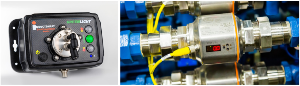
Monitor de concentración (izquierda) y válvulas de la tubería del sistema de temple (derecha) | Crédito de la imagen: Inductoheat
Con el paso del tiempo, parte del agua del fluido de temple se evapora, incrementando la concentración del polímero. Además, el fluido se contamina con residuos de aceite, virutas metálicas y otras impurezas. Los filtros tipo bolsa del sistema se saturan y los múltiples orificios de las boquillas de aspersión pueden obstruirse debido a la acumulación de incrustaciones y partículas. Por ello, el sistema de temple debe recibir mantenimiento periódico para garantizar un enfriamiento controlado y repetible. Solo así el proceso de tratamiento térmico puede completarse de manera consistente y confiable.
Confiabilidad basada en datos
Los equipos de inducción deben operar con un alto nivel de precisión para lograr el tratamiento térmico especificado. Cuando estos sistemas incorporan monitoreo en tiempo real y adquisición de datos durante el proceso, se incrementa aún más la confianza en los resultados obtenidos. El monitoreo mediante “firmas” de proceso mide las múltiples variables del tratamiento térmico por inducción en cada ciclo. Esta “firma” puede incluir parámetros eléctricos como la potencia del inversor, la corriente, el voltaje y la frecuencia a lo largo del proceso. Asimismo, puede registrar la temperatura del medio de enfriamiento, el flujo y la presión del fluido de temple, así como la velocidad de escaneo de la máquina y la velocidad de rotación del husillo. Para cada una de estas variables se establece un rango de variación permitido, el cual se representa gráficamente en función del tiempo. Cualquier desviación fuera de estos límites durante el ciclo, hará que la máquina genere un fallo de proceso.
Firma de proceso del sistema QAS de Inductoheat, mostrando los límites superior e inferior permitidos y el registro de variables como la potencia del inversor (kVA), la velocidad de escaneo y el caudal de temple de los husillos izquierdo y derecho | Crédito de la imagen: Inductoheat
Esta funcionalidad constituye un elemento fundamental dentro de un sistema de aseguramiento de la calidad (QAS por sus siglas en inglés), ya que garantiza la confianza durante cada turno de producción. En el caso de componentes automotrices identificados mediante códigos de barras u otros marcadores únicos, también permite garantizar la trazabilidad de los componentes tratados térmicamente, almacenando la firma del proceso y asociándola a cada componente tratado térmicamente. Este paso permite obtener datos clave para aislar un lote de piezas si fuera necesario, evitando la necesidad de poner en cuarentena más unidades de las estrictamente necesarias.
Equipos Confiables. Mejores Componentes. Vehículos más Resistentes.
En toda la industria automotriz, desde camiones de servicio pesado hasta los SUVs y crossovers de uso cotidiano, el desempeño de un vehículo se construye capa por capa. A medida que las plataformas vehiculares continúan evolucionando, los procesos de tratamiento térmico deben avanzar al mismo ritmo de diseños de componentes cada vez más complejos. Contar con equipos de inducción confiables es fundamental para afrontar estos desafíos. Cada elemento del sistema debe operar con precisión y consistencia. El mantenimiento preventivo, incluido el reemplazo periódico de componentes sujetos a desgaste, como las bobinas de inducción, contribuye a mantener la estabilidad del proceso, obtener resultados consistentes y garantizar una producción confiable.
Para muchos fabricantes, preservar la confiabilidad también implica modernizar sus equipos existentes. Con frecuencia, los sistemas de inducción de mayor antigüedad pueden reacondicionarse mediante la incorporación de controles modernizados, nuevas fuentes de alimentación y componentes críticos actualizados, lo que permite prolongar su vida útil al tiempo que mejora el rendimiento y el tiempo de actividad. Asimismo, estos equipos pueden reacondicionarse para adaptarse a nuevos programas de tratamiento térmico.
Al invertir en tecnología de inducción confiable, los fabricantes pueden seguir produciendo componentes de alta calidad capaces de satisfacer las exigencias de los vehículos actuales.
Acerca del autor:
Aaron Goodwin Ingeniero de Desarrollo de Negocios Inductoheat
Aaron Goodwin cuenta con más de 32 años de experiencia en la industria del calentamiento por inducción, durante los cuales ha desempeñado diversos cargos técnicos en Inductoheat, ubicada en Madison Heights, Michigan. Actualmente se desempeña como Ingeniero de Desarrollo de Negocios, brindando soporte técnico tanto al equipo de ventas como de ingeniería. Entre sus principales responsabilidades se encuentra la dirección del equipo de simulación mediante análisis por elementos finitos (FEA) para el diseño de bobinas y procesos de calentamiento por inducción.
Además, Aaron colabora con las empresas hermanas del grupo Inductotherm alrededor del mundo, impulsando el desarrollo tecnológico, el intercambio de conocimientos y la implementación de soluciones enfocadas en las necesidades de los clientes.
In the second of the two-part series, the Advanced Rapid Quench Jominy Tester application for automotive underbody parts is examined. In this article, Dr. Gopal Nadkarni, an associate professor of mechanical engineering at the University of Akron, explains how automotive manufacturers can integrate this little-used test methodology following existing industry practices. It also makes the case for updating the ASTM A255 Jominy test method to measure enhanced hardenability under modern industrial quenching conditions.
This informative piece was first released in Heat Treat Today’sAugust 2026 Annual Automotive Heat Treating print edition.
Introduction
In “The Jominy and Rapid Quench, Part 1: An American Story” (see Heat Treat Today: Induction Heat Treating, April 2026), the Jominy test adopted in the 1940s was shown to revolutionize how complex metallurgical phenomena in most steels during cooling could be understood using a simplified method of cooling a 4-inch bar of steel from one end. Since then, the ASTM A255: Standard Test Method for Determining Hardenability of Steel (Jominy test) has become the dominant form of characterizing steel behavior under multiple cooling conditions (ASTM International 2020).
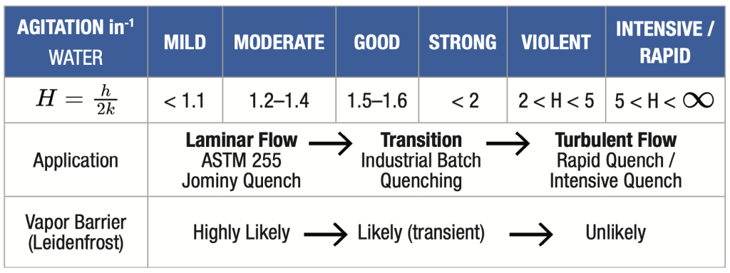
Figure 1. Grossman H values for quenching in water shows the gap between ASTM A255 and current industrial quench practices (modified from Liscic 2010) | Image Credit: Gopal Nadkarni
When the Jominy test was developed, quenching technology relied primarily on relatively mild water agitation (Figure 1). Industrial heat treatment has evolved dramatically since then. These advances raise an important question: Does the traditional Jominy test still represent the cooling conditions experienced by modern industrial components?
The answer is both yes and no. The conventional Jominy test remains an outstanding comparative tool because of its simplicity, reproducibility, and enormous historical database (Chandler 1994). However, improved understanding of quench heat transfer — specifically, the laminar umbrella flow underneath rapidly quenched Jominy test ends hides a “film boiling layer” that impedes heat transfer in the first critical seconds of quenching — suggests that the standard unintentionally limits the maximum cooling rate during the first critical seconds of quenching. Consequently, the hardenability curves engineers have relied upon for decades may not fully represent the hardening potential of steels subjected to today’s rapid or intensive quenching processes.
This article proposes extending the Jominy test’s usefulness through a modified methodology that better reproduces modern industrial quenching conditions while preserving the standardization that has made ASTM A255 indispensable.
Intensive Quenching for Industrial/Automotive Parts
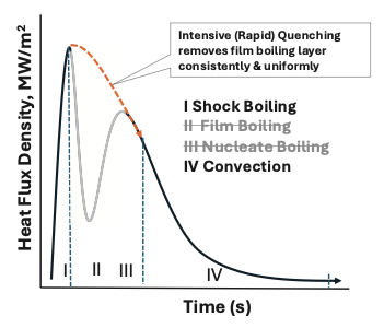
Figure 2. Schematic of heat transfer experienced by quenched parts during cooling with and without the vapor barrier (i.e., Leidenfrost layer) (Modified from Kobasko, et al. 2010)
If methods existed to consistently remove the vapor barrier during the first few seconds of quenching, engineers could increase heat transfer substantially (Figure 2) to maximize hardenability. Dr. Nikolai Kobasko and Dr. Michael Aronov have worked at this theory for the last three decades, demonstrating significant material processing benefits with intensive (or rapid) quench practices. Other scientists have also teamed up with heat treaters in the U.S. to demonstrate commercial adoption of industrial parts (Totten, et al. 2024).
Today, intensive quench practices are being seriously assessed by several automotive manufacturers as a way to not only maximize hardenability, but also to control distortion after quenching, impart beneficial compressive stresses below the surface, and reduce spotty hardness, as well as lower cost and improve sustainability practices by employing lower alloy steels.
Automotive Designs Require Updated Tests
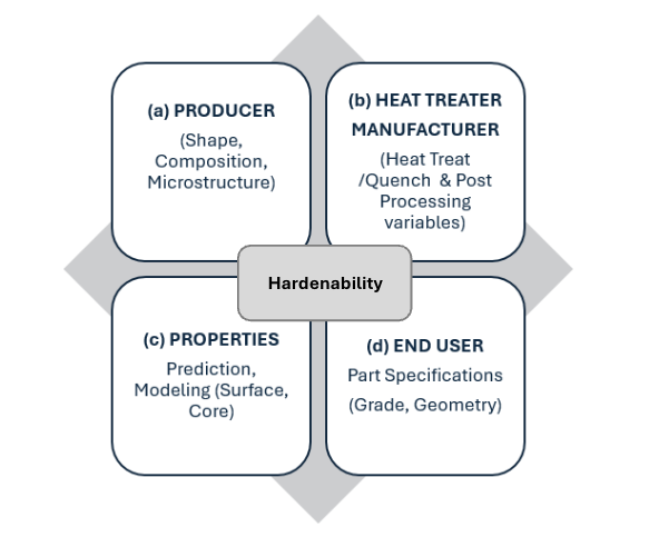
Figure 3. The part production cycle requires a deep understanding of the supply chain variables.
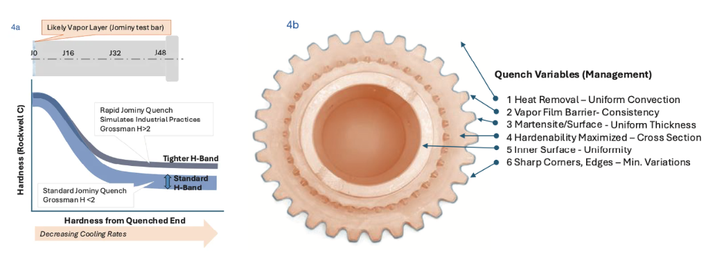
The automotive part production cycle is complex and requires close coordination across multiple stakeholders to achieve desired property outcomes (Figure 3). Designers often rely on “real test” data as input to finite element models to predict critical mechanical properties that correlate with structural life for fatigue, wear, or fracture resistance, with most of these parts being heat treated. They also lean on the correlating structure properties for required parts using the universal ASTM A255 Jominy test as a reference. While this serves as a unique fingerprint for the alloy used, it is by no means an ideal representation of hardenability because chemistry variations that result in a large H-band (Figure 4a).
This approach also falls short because Jominy cooling rates do not reflect real-world quenching, which can be seen as enhanced hardenability under industrial conditions (Figure 4b). Heat treaters use high-velocity forced convective flow to create violent agitation, improve quench consistency, increase hardness, and break up the film boiling layer. However, complex parts like gears pose an issue: it is difficult to guarantee uniformity of instantaneous cooling rates and may only break up parts of the persistent vapor layer (Figure 4b). The result is uneven heat transfer and spotty hardness across the part.
Figure 4. Hardenability is dependent on steel chemistry and microstructure management for the same heat of alloy (a) and uniform quench processing management between batch to batch (b) | Image Credit: Gopal Nadkarni
Automotive part designers need consistent hardness to ensure reliable service and accurate life predictions, but industrial quench conditions do not ensure 100% removal of the vapor barrier. To ensure performance, automotive designers specify higher alloy steels than necessary. In addition, engineering drawings often specify suboptimal surface hardness (suboptimal hardenability) to stay within hardenability realities of accepted heat treatments. Increased costs are often necessary if parts do not hit design targets and require secondary processing (e.g., tempering, carburizing, carbonitriding).
Overcoming Slow Automotive Adoption
Despite excellent data over the past two decades (Kobasko, et al. 2010; Totten, et al. 2024) showing the usefulness of rapid quench technology in maximizing hardenability for bar/plate steels, the paradox is that the technology has been slow to be adopted. We can learn lessons on adopting new steel/processing technologies from the flat steel side used for body-in-white/chassis, where the entire supply chain came together (Auto/Steel Partnership) in 1987 and produced significant lightweighting programs like the 1994 ULSAB (UltraLight Steel Autobody).
If automotive OEMs desire to use the benefits of enhanced hardenability, they must work with the supply chain and standardization bodies (ASTM) to promote widespread adoption. This would allow performance and productivity gains to be adopted at scale quickly.
Intensive quenching has seen limited adoption in mass-produced automotive parts because engineers lack standardized material data that comes after industrial adoption. Therefore, their confidence in process repeatability at scale is not in place. Past experience with promising technologies like austempered ductile iron (ADI) reinforced caution around safety-critical components, especially when processing risks remain difficult to validate. As a result, rapid quenching faces less of a technology adoption challenge than a technology translation challenge: the industry must reduce perceived risk through shared standards, comparable data, and coordinated supply chain validation.
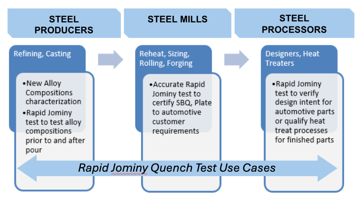
Figure 5. The standard Jominy test is universally used across the supplychain because of its usefulness in specification, standardization, andease of use. The proposed rapid Jominy test could be easily adapted toextend the overall usefulness to measure enhanced hardenability anddevelop new alloy chemistries. | Image Credit: Gopal Nadkarni
The good news is that we have standard methods characterizing hardenability that are well-established and reliable for thousands of grades of steel. For rapid quenching to be acceptable, we need to reduce risk and increase accountability across the supply chain. One way is to extend the current ASTM A225 standard Jominy test used by all (Figure 5) and use proven strategies that flat steel producers used to implement ultrahigh strength designs in steel.
From Theory to Practice: Removing the Vapor Blanket in the ASTM Jominy Test
In short, rapid quenching uses high-pressure, high-velocity water impingement to disrupt the vapor film almost immediately. This allows the surface to transition quickly into nucleate boiling and forced convection, dramatically increasing heat transfer.
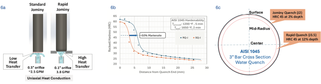
The Jominy test can track the improved hardenability results, if we can make a slight modification to the ASTM 255 test bar design. The modified Jominy test’s critical feature is a flat, tapered configuration versus the traditional flat end face (Figure 6a), and it ensures that the standard uniaxial quench condition is imposed when the bar is sealed in an enclosed chamber. This refinement improves flow control for consistent and repeatable results, therefore providing better alignment with standardized quench conditions used in industry. Another test bar version with a bar end was developed through a university-industry collaborative venture that is useful to measure enhanced compressive stresses (Funk 2021).
The modified bar has been proven to be a close twin of the standard 1-inch diameter bar. The current setup uses a high-pressure nozzle to break up the vapor layer similar to industrial quench conditions and is noticeably different from the laminar flow (H < 1.4) used in the ASTM A225 test. The flow conditions (velocities > 40 m/s, pressures > 120 kPa) have been optimized to ensure that the persistent vapor barrier never forms, achieving high heat transfer rates (H > 5) from the start of quenching till the end of the cooling period.
Figure 6. (a) Schematic of modified Jominy bar to achieve rapid quenching; (b) example AISI 1045 data developed with new tester; and (c) enhanced hardenability due to rapid quenching is estimated to produce ~50% martensite (45 HRC) deeper in a 3-inch diameter bar | Image Credit: Gopal Nadkarni
As a result, current low alloy automotive grades can be quickly analyzed and compared for properties as well as depth of hardening to published hardenability curves, allowing a useful screening tool for adoption.
If heat treaters and steelmakers want to cater to automotive clients who want to reap the benefits of rapid quenching, they need to understand whether their grades are suitable. The simplest approach is to use the rapid quench methodology that has been described here for low alloy steels of interest. This will ensure that true and maximized hardenability data can be used by design engineers to optimize automotive steel parts.
In a recent research study (Nadkarni, et al. 2025), both standard hardenability and true (enhanced) hardenability curves were developed for a benchmark AISI 1045 grade (Figure 6b). The 50% martensite line (45 HRC) is clearly deeper, indicating a significant increase in hardenability, with corresponding Jominy (J in 1/16″) distances moving from J2 to J3.5 (from 3.2 mm to 5.5 mm). An example of how the data can be used practically for a sample 3-inch bar shows that depth of hardening to HRC45 is likely to be significantly higher in rapidly quenched steels (Figure 6c).
The increased hardenability results shown for the benchmark AISI 1045 have been replicated for a wide variety of steels including AISI 1020, AISI 8620, AISI 6150, M50, and tool steels like H13. However, we need to be cautious about extrapolating the results to steels where significant retained austenite can form under enhanced quench conditions.
The significance of adopting such a practice into a new or modified ASTM standard will have global implications. Standardized adoption of advancing technology will support automotive manufacturers in optimizing the performance of their current steel compositions through more controlled distortion and reduced variability in material properties.
Acknowledgements
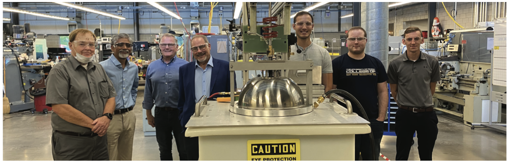
Figure 7. The integrated Jominy Rapid Quench Tester developed at Induction Tooling Inc. for student training and research (Funk 2021). Students at the University of Akron standing with research leadership: Dr. Gopal Nadkarni, University of Akron (second from the left); Bill Stuehr, Induction Tooling, Inc. (third from left); and Joe Powell, Integrated Heat Treating Solutions, Inc. (fourth from left).
ASTM International. 2020. Standard Test Methods for Determining Hardenability of Steel. ASTM A255-20a. West Conshohocken, PA: ASTM International. https://doi.org/10.1520/A0255-20A.
Chandler, Harry, ed. 1994. Heat Treater’s Guide: Practices and Procedures for Irons and Steels. Materials Park, OH: ASM International.
Kobasko, N. I., M. A. Aronov, J. A. Powell, and G. E. Totten. 2010. Intensive Quenching Systems: Engineering and Design. West Conshohocken, PA: ASTM International.
Nadkarni, Gopal. 2026. “The Jominy and Rapid Quench Part 1: An American Story.” Heat Treat Today 9, no. 4 (April): 25–27.
Nadkarni, Gopal, Nafi Bhuiyan, Saikishan Suryanarayanan, and Ryan Souders. 2025. “The Relevance of the Standard Jominy Test for Rapid/Intensive Quenching.” Paper presented at the Heat Treat 2025 Conference & Exposition, Huntington Place, Detroit, MI, October 21–23.
Totten, George E., Rosa Simencio Otero, Xinmin Luo, and Lauralice C. F. Canale, eds. 2024. ASM Handbook, Volume 4F: Quenchants and Quenching Technology. Materials Park, OH: ASM International. https://doi.org/10.31399/asm.hb.v04F.9781627084505.
About The Author:
Dr. Gopal Nadkarni Associate Professor of Mechanical Engineering University of Akron
Dr. Gopal Nadkarni is an Associate Professor of Mechanical Engineering at the University of Akron and manages its Manufacturing Graduate Certificate Program. He brings extensive industry and innovation experience, having held previous leadership roles at industry and in technology ventures, with research and teaching focused on manufacturing, materials, and product design.
To contribute to ongoing industry-academia research regarding this topic, please contact Professor Gopal Nadkarni.
Custom furnace design isn’t just about performance upgrades — it’s about process reliability. Vacuum furnaces built for general use, however, often fall short in high-precision industries. This Technical Tuesday installment comes to us from Scott Herzing, vice president of Engineering at Paulo. Explore how purposeful furnace design, smarter controls, and targeted customization can transform vacuum heat treatment.
This informative piece was first released inHeat Treat Today’sNovember 2025 Annual Vacuum Heat Treating print edition.
The reliability and consistency of vacuum heat treatment processes depend heavily on furnace design and performance. Standard furnace configurations typically serve general heat treating applications adequately. However, for industries with extremely demanding requirements, such as aerospace, automotive, and power generation, small variations in furnace design can lead to substantial impacts on part quality, increasing risks and costs. Achieving exceptional process control and repeatability often requires custom furnace modifications tailored specifically to the unique requirements of each process.
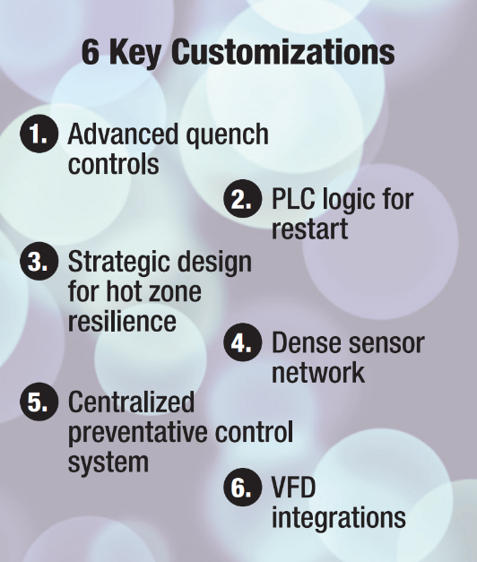
Extensive customization of vacuum furnaces can initially seem costly and complex. It takes experience operating and refining vacuum furnaces to know which adjustments deliver the greatest impact. This article taps into the more than fifty years of heat treating wisdom from Paulo with six key factors that drive better furnace performance, enhance reliability, reduce downtime, and create measurable efficiency gains.
Why Customization Matters
Conventional vacuum furnace models offered by manufacturers are generally designed to meet broad market demands. This often results in equipment that effectively balances functionality, affordability, and ease of use for a wide range of applications. However, certain high-precision thermal processing applications, especially those involving aerospace components like single-crystal turbine blades demand much stricter temperature uniformity, controlled quenching rates, and near-perfect repeatability from cycle to cycle.
In these cases, standard configurations can introduce variability that compromises quality. A better path is a case-by-case approach, evaluating specific process risks and targets critical components for modification. Precision upgrades can be integrated where they have the greatest impact, achieving the required level of process control. This makes it possible to achieve near-zero scrap rates, dramatically boost reliability, and achieve repeatability that far exceeds industry norms.
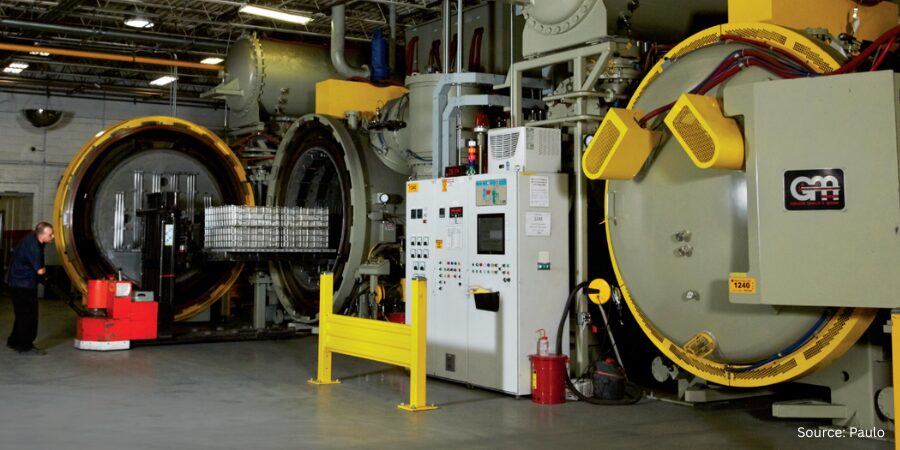
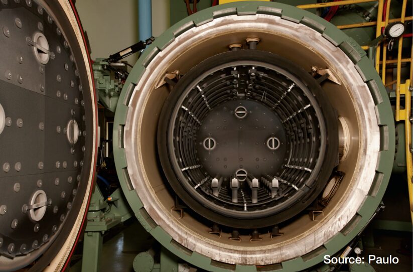
Interior of vacuum furnace
Advanced Pressure and Cooling Control
Repeatable quench dynamics is a game-changer when it comes to part quality. Integrating advanced gas control capabilities that extend beyond basic pressure management can help you improve heat treating results. To do this, you need to precisely control the rate at which gas is introduced into the vessel using proportioning valves, not just the pressure setpoint. For controlled cooling cycles, systems also need to manage the fan start speed, allowing you to tailor the convective heat transfer to the geometry and mass of each part. This level of precision ensures consistent metallurgical results and protects part integrity.
Automation-Ready Resilience
In multi-furnace environments that rely on automation and minimal staffing, power-failure restart behavior cannot be left to chance. Adding dedicated PLC logic for restart allows the system to record the exact state at interruption, verify safe conditions on recovery (atmosphere, temperature, motion, interlocks), and automatically sequence a safe restart when criteria are met. This reduces scrap risk, protects equipment, and stabilizes throughput, especially when only a few operators are covering many furnaces.
Hot Zone Design and Material Selection
A major component directly influencing furnace reliability and overall performance is the hot zone. As the central area where thermal processing occurs, the hot zone repeatedly experiences extreme temperature fluctuations, making its design crucial to operational efficiency and product quality.
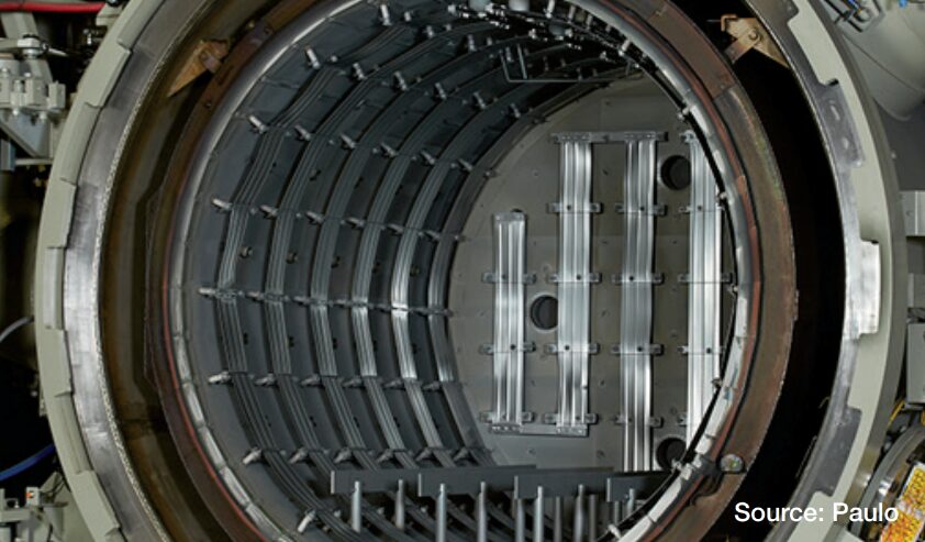
Standard vacuum furnaces use thinner insulation layers and lower-cost materials to control initial investment costs. However, advanced hot zones can dramatically outperform these standards by incorporating thicker insulation layers, strategically placed air gaps, and specialized insulation materials, such as high-quality molybdenum, graphite felt, or carbon-fiber-carbon (CFC) boards.
Vacuum furnace hot zone
These advanced materials not only prolong hot zone life but also substantially reduce heat loss, minimizing energy consumption and improving thermal uniformity. The enhanced durability also results in fewer service interruptions, less downtime, and lower long-term maintenance costs, ultimately justifying the higher initial investment. At Paulo, this is how we’re able to reliably run around 29,000 cycles per year in over thirty furnaces at our Cleveland facility.
Additionally, the hot zone’s construction details, including how insulation and heating elements are attached, can significantly affect longevity and reliability. Standard fasteners or attachment mechanisms may perform well in general applications but frequently deteriorate under high-stress thermal cycling. High-performance fasteners specifically engineered for high-temperature stability reduce the risk of premature failure and minimize downtime.
Enhanced Sensor Integration
Furnace reliability and consistency rely heavily on the accuracy, quantity, and strategic placement of sensors within the furnace chamber. Manufacturers’ vacuum furnace designs typically include a limited number of sensors monitoring basic parameters, such as temperature, pressure, and vacuum levels. Increasing the number and distribution of sensors throughout the furnace interior allows for a more detailed and accurate understanding of conditions during processing. By placing multiple sensors at critical points within the hot zone and throughout key furnace components, operators can detect subtle differences in temperature distribution, heat flow, gas pressures, and quench rates that might otherwise go unnoticed. This enhanced sensor density provides the detailed data necessary for real-time process adjustments, early detection of equipment issues, and predictive maintenance interventions, significantly improving process reliability and part consistency.
In addition, the rich data captured by a denser sensor network improves traceability and enables rapid identification of root causes when process deviations occur, ultimately reducing the risk of quality issues and equipment downtime.
Centralizing Your Control System
One often-overlooked factor in achieving highly consistent heat treating results is the adaptability and responsiveness of furnace control systems. Modern furnace control architectures benefit from a centralized SCADA layer with deep PLC integration. By recording every PLC input (thermocouples, switches, interlocks, drives, flows, pressures), the system enables technicians to diagnose issues without walking out to the furnace and manually testing components. With complete signal histories available, furnace issues can often be diagnosed and resolved remotely in minutes, improving first-pass resolution and minimizing production disruption.
Integrated control software should do more than log data; it should actively protect quality:
Automated compliance control: Continuously track process parameters, alarm on deviations, and initiate quality quarantines when limits are exceeded to prevent suspect parts from re-entering the supply chain.
Element-health monitoring: Monitor heating-element resistance to detect early signs of a heating system issue. If an anomaly is detected, automatically stop the heating process to protect parts and prevent secondary furnace damage.
These safeguards shift intervention upstream and reduce reliance on manual inspection alone.
Extending Auxiliary Equipment Life with VFDs
Variable-frequency drives (VFDs) on pumping systems can substantially extend motor and bearing life by matching speed to process demand and reducing mechanical stress. When control logic conditions are met, slowing pumps lowers load, heat, and vibration, which are key contributors to premature failures.
Without VFDs: Bearings on 615 blowers typically require replacement every 1–2 years, and motor failures occur more frequently than acceptable.
With VFDs + logic-based speed reduction: Bearing-change intervals extend to 10–20 years, with no motor problems, reflecting a step-change in reliability and lifecycle cost.
This targeted upgrade is a practical, high-ROI improvement that also helps decrease unplanned downtime.
Practical Realities and Final Considerations
Extensive furnace customization offers clear advantages, but it is not always practical for every operation or budget. In many cases, targeted, incremental upgrades — such as refining hot-zone insulation and attachment methods, adding or repositioning select sensors, or phasing in improved control software and deeper data storage/analysis — deliver measurable gains in reliability and process quality without large upfront costs.
Another practical path is to partner with a commercial heat treater that has already engineered and validated these enhancements at an industrial scale. This option can accelerate access to higher levels of precision and repeatability without requiring capital investment, engineering bandwidth, and learning curve of doing it all in-house.
Ultimately, achieving reliable and repeatable heat treatment results involves careful consideration of furnace design and functionality, aligned closely with your process requirements and economic realities. While extensively customized furnaces represent the ideal for particularly demanding applications, understanding the targeted areas where smaller customizations can yield significant improvements empowers heat treaters across the industry.
About The Author:
Scott Herzing Vice President of Engineering Paulo
Scott Herzing is vice president of Engineering at Paulo. He leads the company’s metallurgical, project and automation engineering, fabrication, and lean technology groups. With over 27 years at Paulo, Scott applies his passion for leadership, engineering, and problem-solving to help customers achieve advanced heat treating outcomes.
For more information: Contact Scott Herzing at sherzing@paulo.com.
Ferritic nitrocarburizing (FNC) has emerged as a powerful, low-distortion heat treatment solution for automotive components, especially brake rotors, thanks to its wear resistance, corrosion protection, and compatibility with tight dimensional tolerances.
In this Technical Tuesday installment, adapted from a recent Heat Treat Radio conversation, Mike Holly, a retired GM metallurgical engineer, shares how FNC reshaped brake rotor technology at General Motors (GM), and what its future may hold for commercial and in-house heat treaters alike.
This informative piece was first released inHeat Treat Today’sAugust 2025 Annual Automotive Heat Treating print edition.
A Brake Rotor Problem Worth Solving
Ferritic nitrocarburizing (FNC) may not be new to the thermal processing world, but its potential is still unfolding, especially for heat treaters working with automotive components. With over four decades in the automotive and heavy truck industry, 32 of those with GM, Mike Holly’s perspective is forged in real-world experience. In the mid-2000s, he and a colleague tackled a costly issue: brake rotor warranty claims due to pedal pulsation and corrosion. The solution? FNC, if it could be controlled tightly enough to meet the dimensional demands of finished machined rotors.
From Concept to Production
Working with Kolene (in salt bath) and later Woodworth (in gas), the GM team optimized the process to FNC rotors after finish-machining without subsequent grinding. Stress relieving the castings ahead of machining helped eliminate dimensional shifts. This process innovation led to multiple patents and debuted in the 2009 Cadillac DTS and Buick Lucerne. Today, it’s used widely across GM platforms and by other OEMs.
Figure 1. Doug Glenn and Mike Holly discussing laser cladding, grinding, and carbides in FNC
Initially, implementation required close collaboration with external heat treaters and careful process validation. GM chose to pilot the technology on low-volume, premium platforms before expanding to high-volume vehicles like trucks.
“Eventually,” said Holly, “the best setup was to co-locate FNC operations with machining and casting facilities. That reduces shipping costs and protects dimensional tolerances.”
Why FNC Works
“FNC is a thermal chemical case hardening process,” Holly explained. “It diffuses nitrogen and carbon into ferrous materials at subcritical temperatures, typically 560 to 590°C (1040°F to 1090°F). That creates a hard, wear- and corrosion-resistant surface with minimal distortion.”
The benefits are compelling: compressive residual surface stress improves fatigue life; resistance to adhesive and abrasive wear boosts durability; and there’s virtually no hazardous waste. For heat treaters managing precision parts or looking to support sustainability goals, FNC checks several boxes.
Unlike carburizing or carbonitriding, FNC operates below the critical transformation temperature of steel. This means fewer dimensional changes and minimal phase transformations, making it ideal for components that have already been finish-machined. Parts emerge from the process with a compound layer and a diffusion zone that enhances performance without requiring post-processing.
Figure 2. Close up photograph of a disc brake. Source: Pexels/Agustin Olmedo
Still, it’s not for every application. “The shallow case depth (10 to 20 microns) limits FNC’s use in high-load or rolling contact fatigue applications, like ring and pinion gears,” said Holly. “But for lightly loaded gears, brake backing plates, clutch discs, and now brake rotors, it’s a great fit.”
To make FNC viable for finished parts like brake rotors, precise control over fixturing and orientation is essential. “Vertical orientation in the furnace is crucial,” said Holly. “And you must stress relieve parts, at least where the geometry or casting process warrants it.”
Fixturing strategies are typically proprietary to commercial heat treaters, but OEMs require dimensional accuracy to be statistically validated. Proper stress relief, careful racking, and consistent atmosphere control are all part of ensuring tight tolerances and minimizing scrap.
Applications Beyond Brakes
FNC isn’t just for brake rotors. It’s used in numerous applications where wear, corrosion resistance, and dimensional control are critical. Lightly loaded gears, hood struts, locking mechanisms, clutch pack discs, and brake backing plates all benefit from FNC.
In non-automotive sectors, FNC has been applied to hydroelectric gates, military components, and even stainless steels where added surface strength and wear resistance are needed.
Opportunity for Heat Treaters
For in-house and commercial heat treaters, the expanding use of FNC presents an opportunity. Whether supplying OEMs or developing in-house capability, the process can offer a competitive edge in applications requiring low distortion and enhanced surface properties.
Figure 3. Hydroelectric gates can benefit from being FNCed
However, Holly emphasizes that consistency and precision are paramount. OEMs, he explained, don’t need to know the proprietary fixturing methods used by commercial heat treaters, just that the finished parts meet all dimensional specifications.
“Show us statistically that your lateral runout, your thickness and your wheel mount surface meet our specs,” he said.
In-house heat treat operations should prioritize tight process control, consistent dimensional outcomes, and scrap minimization. As with most thermal processes, success lies in mastering the details.
Preparing for Euro 7
The process’s low temperature and environmental profile are key drivers. And now, its role in upcoming regulatory changes could make FNC even more relevant. The European Union’s Euro 7 regulation, expected to begin rolling out in 2026, includes strict limits on brake dust emissions. Holly sees two viable solutions on the horizon: FNC and laser cladding.
“FNC with niobium alloying is the low-cost alternative,” said Holly. By alloying gray iron brake rotors with niobium before FNC, Holly’s team is developing enhanced surface hardness through niobium carbides, without post-process grinding or exotic feedstocks. It’s a scalable path for meeting wear and emission goals while keeping costs in check.
Alloying for the Future
In response to Euro 7 and increasingly aggressive friction materials, Holly is working with clients to improve the case properties of FNC rotors through alloying. Niobium, a known carbide-former, is added during the casting phase to enhance both case and core properties.
“There is a heavy truck rotor application that was niobium alloyed for many years, and that was advertised as a 1-million-mile rotor,” said Holly. “In the heavy truck industry, it’s all about uptime — keeping the trucks out of the shop and on the road.”
This alloying strategy leverages existing infrastructure and doesn’t require major capital investment, a significant advantage over competing technologies like laser cladding, which demands specialized equipment, multiple process steps, and expensive materials.
Cladding vs. FNC: The Economic Equation
While laser cladding offers impressive wear resistance, it brings substantial cost and environmental considerations. The materials involved (nickel, chromium, molybdenum) are expensive and volatile. Post-process grinding generates nickel-laden swarf, which requires special handling and disposal.
FNC, by contrast, uses common gases like ammonia and natural gas. It’s performed in batch processes that are well-suited to high volumes and heavy parts. And it can be integrated into existing facilities without massive investment.
While cladding may be necessary for extreme-duty applications, FNC, especially with niobium alloying, offers a highly competitive solution for most mainstream automotive needs.
The Road Ahead
As regulatory pressure increases and OEMs push for performance and sustainability, FNC is well-positioned to meet the challenge. Holly continues consulting with clients in North America, Europe, and South America, supporting FNC development and publishing papers at industry events like SAE Brake Colloquium and EuroBrake.
For heat treaters, whether in-house or commercial, staying ahead means understanding not just the metallurgical fundamentals but also the evolving regulatory and performance landscape. FNC presents heat treaters with a scalable, efficient, and regulation-ready solution to meet evolving performance and emissions demands.
About The Expert:
Mike Holly Lead Consultant Mike Holly Metals LLC
Mike is currently a consultant with Mike Holly Metals LLC, specializing in heat treatment, coating, casting, metal forming and joining operations. He has 42 years of experience in industry, including 32 years at the General Motors Materials Engineering department where he was assigned to support automotive and truck chassis applications. He holds 15 patents and was key in the development of Ferritic Nitrocarburizing Brake Rotors. Mike has a bachelor’s degree in metallurgical engineering from Wayne State University and a master’s degree from Purdue University.
For more information: Contact Mike Holly at mike.holly72@att.net.
To listen to Heat Treat RadioEpisode 117: How GM Started & Grew FNC for Brake Rotors click here.
In this Technical Tuesday installment Christoph Bollgen, industry manager for Thermal Processing Technology, JUMO GmbH & Co.describes how global industries accelerate towards greener, smarter manufacturing. Thermal processing is at a pivotal crossroads of advances in industrial furnace technology, energy efficiency, and sustainable operations set to transform how materials are hardened, strengthened, and perfected.
This feature presents these important developments in thermal processing — from technological developments and energy efficiency measures to digitization, sustainability, regulation, and market growth — supported by current analyses, statistics, and case studies.
This informative piece was first released inHeat Treat Today’s August 2025 Automotive Heat Treating print edition.
Introduction
Thermal processing technology, specifically industrial furnaces and heat treatment processes, are the backbone of numerous industries from steel and ceramics to automotive and electronic components. Over the last five years, this sector has developed rapidly. Driven by new technical possibilities and increasing requirements relating to efficiency and sustainability, significant trends have arisen in industrial furnaces, heat treatment processes, and the market as a whole.
Industrial process heat is essential for many industries, which is why increasing energy costs, regulatory requirements, the shortage of skilled professionals, and international competition pose challenges for companies.
Electrification is increasing in importance, as it offers high process efficiency, emissions reductions, and tried-and-tested technologies. Nevertheless, there are technical and economic obstacles for high temperature processes where limited heat flux densities and high operating costs make complete electrification more difficult.
Hydrogen is being investigated as a possible option for decarbonization in industries that currently use natural gas. However, for the switch to take place, changes to process conditions and material properties are required, while the availability and cost of hydrogen remain decisive factors.
Future decarbonization strategies must be developed for specific industries, as not all processes can be electrified. Both hydrogen and electrical energy require significant changes to the infrastructure to ensure supply security in the long term. The choice between electrification and hydrogen depends on underlying technological, economic, and infrastructure conditions.
Advances in Industrial Furnaces and Heat Treatment Processes
State-of-the-art industrial furnaces and heat treatment systems have made huge advances in a short period of time. Key examples are the new, altered material and product requirements in the automotive industry; more lightweight components and electromobility place higher demands on components, such as rolling bearings. This has resulted in process innovations.
Carbonitriding of bearing steel has therefore experienced somewhat of a renaissance, as it facilitates higher levels of power density and temperature resistance. At the same time, low-distortion steels are being developed for lightweight construction, and modular heat treatment processes (e.g., nitriding and low-pressure carburizing) are being introduced to adapt processes more flexibly to different workpieces.
Progress has also been achieved when it comes to the furnace technologies themselves. New furnace designs combine multiple process steps in a single plant and make better use of energy. For example, pre-heating, heating up, and melting are combined in a single furnace shaft in modern shaft furnace designs. This makes maximum energy yield possible, thanks the smart geometry and burner technology. Due to the installation of these types of new melting furnaces, gas consumption and therefore energy costs can be reduced significantly.
Figure 1. Comparison of old and new industrial furnace technologies
In addition, compact furnace constructions are gaining in importance, as space-saving, modular furnaces enable integration in confined production environments, without compromising capacity or temperature homogeneity.
Finally, induction technology is also increasingly being used in heat treatment — for example for inductive hardening of complex components — as it combines precise local heating with high energy efficiency. Overall, technical progress aims at achieving higher product quality with lower side effects (e.g., distortion, energy consumption, scrappage).
Measures for Improving Energy Efficiency
In light of increasing energy costs and strict climate targets, energy efficiency in thermal processing plants is once again in the spotlight. Over the past five years, various measures have been established to reduce the energy consumption of furnaces and heat treatment processes.
Optimized Furnace Insulation and Construction
Manufacturers are increasingly relying on improved insulating materials and energy-efficient furnace constructions to minimize heat loss. State-of-the-art industrial furnaces have highly effective insulation and sophisticated flow guidance, meaning less unused energy escapes. This therefore significantly reduces the specific energy demand per processed piece.
Heat Recovery
Nowadays, unavoidable waste heat is better exploited. New technologies (e.g., high-temperature heat pumps or ORC systems) can raise waste heat to a usable temperature and guide it back into the process or use it for electricity generation. This waste heat recycling reduces the use of primary energy and, accordingly, emissions. McKinsey & Company (2022) estimates the global waste heat potential that can be exploited to be at least 3,100 TWh annually, which could mean savings of up to €140 billion (US$164 billion) per year if used in full. In practice, recuperators, regenerative burners, and heat exchangers are part of the standard equipment of many furnaces to reuse energy from hot exhaust gases for pre-heating processes.
More Efficient Burners and Process Control
Progress in burner technology also plays a role in achieving savings. Industrial gas burners currently operate with improved air pre-heating or flameless oxidation (FLOX) modes, which increase efficiency and reduce losses. Precise digital control systems (with PID controllers and recipe programs) also ensure that furnaces remain in the target temperature range with increased accuracy. Avoiding overshoots (overheating) in heating-up and cooling-down phases saves energy and shortens process times. Intelligent control algorithms and sensor technology ensure that the temperature distribution is more even, meaning fewer readjustments are required.
Figure 2. How various measures help boost energy efficiency (Data from Future Market Insights, Inc. 2025, McKinsey and Company 2022, and Neal Systems Incorporated)
Modernizing and Replacing Old Plants
Many companies are investing in replacing outdated furnaces with new, energy-optimized systems. These types of modernization efforts — often funded by state energy efficiency programs — boost productivity and reduce energy consumption by double digits in no time. Retrofits (e.g., improved insulation, speed-controlled drives for fans, automatic door locks) also noticeably boost the efficiency of existing furnaces.
These measures pay off both economically (thanks to reduced operating costs) and environmentally (thanks to reduced emissions). Efficient thermal processing technology has therefore become a core concern for the industry.
Digitization and Automation in Thermal Processing Technology
Industry 4.0 has reached thermal processing technology over the last few years. Automation and digitization are now the most important drivers of growth in this sector. Specifically, a range of state-of-the-art technologies are used in furnaces and heat treatment systems.
IoT-Capable Furnaces and Interconnected Sensor Technology
New industrial furnaces are equipped with sensors (e.g., temperature, pressure, atmospheric composition, wear monitors) and communicate their operating data in real time. These types of smart furnaces enable the process to be continuously monitored and fine-tuned. The data gathered is evaluated in control systems, which boosts operating efficiency and reduces downtimes. For example, trends in temperature curves or burner parameters can provide early indication that maintenance is required. Operators can therefore achieve interruption-free production processes thanks to predictive maintenance.
Predictive Maintenance and Digital Twins
Instead of reactive maintenance, many companies rely on predictive maintenance. Upcoming plant failures can be predicted using machine learning from sensor data. Digital models (twins) also simulate the furnace behavior and facilitate parameter optimization, without interrupting real-time operation. According to a market analysis, these types of virtual simulations are used to plan preventative maintenance and optimize processes. This boosts plant availability and extends maintenance intervals.
Consistent Automation and Reliable Control Systems
Today, thermal processing plants use PLC/CS systems to automatically control operations and can coordinate multiple connected furnaces or burners centrally. State-of-the-art control systems meet high safety standards (e.g., according to EN 746-2 or ISO 13577 for burner safety), meaning that even complex plants can be operated in compliance with standards and fail safety. This trend toward safely automated thermal processing plants has been further advanced thanks to new standards and digital control technology, among other things.
Integration of AI and Autotuning Systems
The first AI-based optimization systems are being implemented to improve thermal processing in real time. Systems like this learn from process data and adapt parameters (e.g. furnace atmosphere, power control) automatically to further reduce energy consumption or throughput time.
Robots and Automation of Handling
Alongside furnace control itself, the material handling process is also increasingly being automated. In modern hardening plants and foundries, robots deal with the loading and unloading of furnaces and transport workpieces between process steps, thereby boosting process reliability and reproducibility. This reduces errors due to manual interventions and enables low-personnel or lights-out operating concepts.
Overall, digitization results in higher flexibility, quality, and availability in thermal processing technology. Companies that make use of heat treatment 4.0 can respond to new production requirements more quickly and operate their plants more cost-effectively as a whole. The industry is transitioning toward data-driven, intelligent systems that are transforming traditional furnaces into high-tech interconnected systems.
Developments in the Field of Sustainable and Environmentally Friendly Technologies
Against the backdrop of climate change and environmental requirements, thermal processing providers are increasingly promoting sustainable technologies. A key aim is to decarbonize industrial heating processes — in other words to drastically reduce CO₂ emissions and other pollutants. Multiple developments over the last few years should be highlighted here.
Electrification of Heating Processes
Wherever possible, fossil fuel-fired furnaces are being replaced by electric heating processes. Electric heat (e.g. induction furnaces, resistance heating furnaces, or electric arc furnaces) does not cause any direct emissions locally and can be operated practically CO₂-neutrally using green electricity. Electric high-temperature heat pumps, electric boilers, and furnaces are increasingly gaining in popularity, particularly for low temperature ranges or discontinuous processes.
However, there are challenges. In some industries, gas-fired furnaces are still more cost-effective due to higher electricity prices — even though electric furnaces often operate more efficiently. Although fully electric melting furnaces in the glass industry may be more energy-efficient, they cannot yet achieve the capacities of larger gas furnaces and may result in higher operating costs depending on the region. Nevertheless, the proportion of electric heat treatment systems is continuously rising, especially as the investment costs are often lower (no fuel storage, no exhaust gas cleaning required).
Hydrogen and Alternative Fuels
High hopes are resting on green hydrogen as a replacement for natural gas or oil in industrial furnaces. Hydrogen burns without producing any CO₂ if it originates from renewable sources — the only product that is created is water vapor. However, hydrogen requires a modified furnace design and safety precautions due to different combustion properties (faster flames, higher temperature peak). Nonetheless, initial pilot plants such as those in the steel and brick industry, successfully demonstrate operation with hydrogen burners. Ammonia is also being trialed as a storable hydrogen carrier (in particular in Japan) in order to provide carbon-neutral process heat.
Emission-Free Combustion Technologies
Regardless of the fuel, there is a focus on reducing harmful gases such as NOx. Technologies such as flameless oxidation (FLOX) and staged combustion drastically reduce NOx formation by smoothing combustion peaks. Some manufacturers are making their names as pioneers in low-emission technologies in furnace construction. Improved filter and afterburning systems are also being integrated to remove particles, VOC, and CO from exhaust gases. State-of-the-art thermal processing plants therefore often significantly fall below current limit values and minimize local air pollutants.
Energy Management and Renewable Integration
Sustainability is also reflected in plant energy management. Many companies are integrating their furnaces into energy recovery cycles or using excess heat to heat other plant components or buildings. Some heat treatment companies are investing in their own renewable energy sources (photovoltaics, wind) or are purchasing green electricity to lower the CO₂ footprint of their processes.
For example, in the aluminum recycling industry, AI systems (as mentioned above) are used to reduce the use of new aluminum and melt more scrap, which saves a significant amount of energy. These types of holistic approaches — closing the material cycle, using waste heat, employing green electricity — play a role in ensuring environmentally friendly thermal processing technology.
As a whole, the industry is making significant strides toward climate neutrality and resource conservation. Numerous providers and industrial companies have set voluntary targets or commitments to reduce their process-related emissions by large percentages by 2030 or 2040. The course is set in terms of technology (electric processes, hydrogen as an option, highly efficient furnaces) to make this transformation possible.
Regulatory Developments and Underlying Legal Conditions
The trends described are strongly impacted by laws and regulations. Over the last few years, legislators around the world have enacted an increasing number of rules which also impact thermal processing technology.
Environmental Regulations and Emission Limits
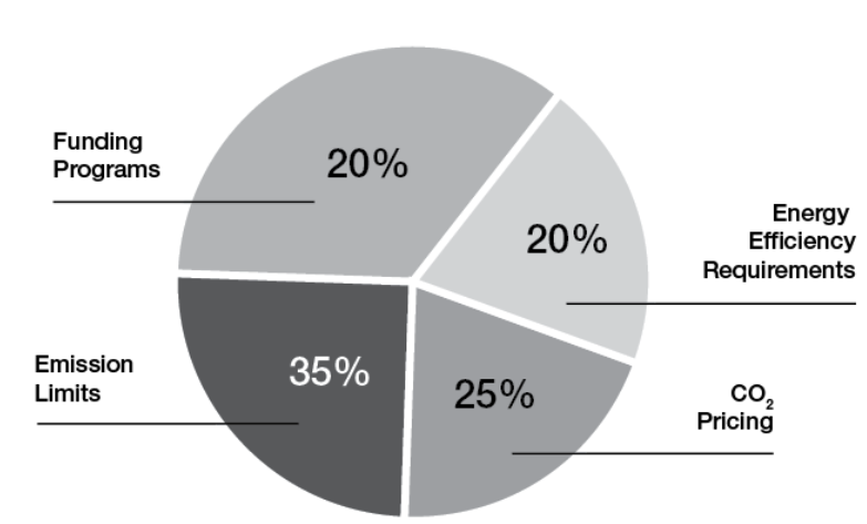
Figure 3. Impact of regulations on thermal processing technology (Data from BMUV 2021 and European Commissions 2026)
There are now strict limit values for exhaust gases from industrial furnaces (NOx, CO, particulate matter, etc.) in many regions. For example, the permitted emissions have been tightened up further in the EU with the Technical Instruction on Air Quality Control 2021 and the Industrial Emissions Directive. Manufacturers are responding to this with the low NOx technologies mentioned above as well as more efficient combustion in order to adhere to the strict environmental regulations. The permitted CO₂ emissions are also being limited indirectly — by such means as national CO₂ prices or emission trading schemes which make fossil fuels more expensive. This creates an economic incentive for switching over to more efficient or CO₂-free technologies (electric heat, H₂).
For example, China’s state “dual carbon” strategy aims at reaching peak CO₂ early and then becoming climate-neutral – which is pushing the local heat treatment industry to upgrade to energy-efficient and environmentally friendly plants quickly. Similar climate protection programs in Europe (Green Deal/Fit for 55) and the U.S. (Industrial Heat Shot, 85% emission reductions by 2035) exert pressure globally to make thermal processing plants greener.
Energy Efficiency Requirements and Promotion
Many countries have legal targets for reducing industrial energy consumption. For example, the Energy Efficiency Directive in the EU means large companies are obligated to carry out audits which often uncover potential for greater efficiency in thermal processing. Germany and other countries are funding investment in energy-efficient interdisciplinary technologies — explicitly including industrial furnaces.
Companies receive subsidies or tax breaks if they replace old plants with efficient ones or introduce utilization of waste heat. For example, in the case of Hattori in Japan, a state funding program helped it to finance the purchase a new melting furnace. This type of funding significantly speeds up the market penetration of state-of-the-art technologies.
Safety and Quality Standards
These underlying legal conditions not only relate to the environment, but also to safety and quality. The EN standards series 746 (or ISO 13577 et seqq.) for thermal processing plants has recently been updated to represent the current state of technology — for example with respect to the functional safety of burner controls. Operators are instructed to equip their plants according to these standards, which makes the use of advanced control technology necessary. In safety-critical industries (e.g., aerospace), standards and customer requirements also require each heat treatment process to be documented in detail (AMS2750 or Nadcap in heat treatment). This promotes digitization (for example electronic batch reports, traceable sensor technology calibrations) and ensures that new technologies operate reliably and in a reproducible manner.
All in all, regulations both put pressure on companies and create incentives: on the one hand, stricter laws force companies to make changes (any company which operates inefficiently or produces a high level of emissions, risks penalties or competitive disadvantages); on the other hand, funding programs mean that making the switch is easier. The thermal processing technology industry is current operating in an environment which is strongly influenced by climate and industrial policy objectives — and therefore responds with innovations to meet these objectives.
Market Growth and Predictions for the Years Ahead
The thermal processing technology market is characterized by solid growth thanks to the above-mentioned trends. Around the world, the market volume of industrial furnaces and heat treatment systems is expected to grow further. According to a current analysis (Future Market Insights), the global market grew to a volume of around USD 10.26 billion in 2024 and is expected to grow to above USD 17.1 billion by 2035; this corresponds to an average annual growth rate of around 4.8% (2025–2035).
Figure 4. Distribution of energy sources in thermal processing technology (Data from Future Market Insights, Inc 2025 and Leicher, Giese, and Wieland 2024)
Industries and regions: almost all user industries contribute to market growth, in particular the automotive industry. Significant markets such as Europe and North America are experiencing somewhat more moderate growth but are increasingly carrying out high-tech upgrades to existing plants.
Market character and outlook: the thermal processing technology market is highly diversified, spanning large continuous furnaces for mass production to specialized laboratory furnaces. Customized solutions are gaining in importance, as manufacturers are increasingly having furnaces tailored precisely to their process requirements.
Conclusion
The thermal processing industry has noticeably changed over the last five years. Modern industrial furnaces and heat treatment processes are more efficient, digitally networked, and significantly more environmentally friendly than their predecessors. Companies are investing in energy-efficient, automated plants to both reduce costs as well as meet regulatory and climate-relevant requirements. These trends will continue over the upcoming years.
Further market growth can be expected, while the technologies also evolve toward sustainability and smart manufacturing. The combination of innovation and adaptability mean that thermal processing technology will secure a central position in the industrial value chain in the future.
Leicher, Jörg, Anne Giese, and Christoph Wieland. 2024. “Electrification or Hydrogen? The Challenge of Decarbonizing Industrial (HighTemperature) Process Heat.” J 7 (4): 439–456. https://doi.org/10.3390/j7040026
Over the last eight years, Christoph Bollgen has made an incredible journey from a college teaching assistant to the Market Segment manager at JUMO Process Control. Along the way, Christoph earned a bachelor’s degree in automation and robotics from the University of Applied Science Fulda, Germany, and received a master’s degree in industrial engineering from the University of Texas in Arlington. After joining JUMO, Christoph successfully participated in the CQI-9 Process Auditor training in 2019 and in the 2019 SECO/WARWICK Heat Treatment 4.0 Seminar, gaining expertise about topics such as theoretical and practical issues of heat treatment 4.0 concerning aircraft, automotive, mass production, and hardening industries.
Christoph was also an honoree in Heat Treat Today’s40 Under 40Class of 2024.
The increasing adoption of large-scale aluminum die casting, often termed Giga casting, in the automotive industry presents significant challenges in the manufacturing and maintenance of the massive dies required. Learn how heat treatment plays a critical role in ensuring the performance and lifespan of these Giga dies, primarily made from H13 tool steel or its derivatives.
This informative piece was first released inHeat Treat Today’sMay 2025 Sustainable Heat Treat Technologies print edition.
Introduction
In an article from 2005 on vacuum heat treating of large dies, I concluded, “The use of very large die cast tooling in the automotive industry with part weight over 3 metric tons will increase as aluminum cast parts are increasingly used to lower the manufacturing cost to produce lighter weight automobiles” (Wingens, “H13 Dies.”). Now, 20 years later, a couple hundred “Mega” dies have been heat treated. Six years ago, Tesla decided to take on Giga casting, gaining global attention and taking aluminum die casting to its next level.
Tesla is working on an upgrade to its Giga casting technology to die cast almost all vehicle underbody parts in one piece. They pioneered the use of presses with 6,000 to9,000 tons of clamping pressure to mold the front and rear structures of Model Y during the Giga casting process.
For Tesla, the use of a single component in the rear of the Model Y allowed it to cut related costs by 40%. In the Model 3, Tesla was able to remove 600 robots from assembly by using a single piece from the front and rear of the vehicle (Greco, “Weekly Gigacasting News.”).
Figure 1. Part reduction between Model 3 and Model Y Source: Tesla Q1 2020 Report
They have 14 Giga presses already installed, including two presses with 9,000 tons of clamping pressure for Tesla’s large Cybertruck production at its plant in Austin, Texas, with more to come.
Tesla strategically incorporates inserts in the dies for high-heat zones. These metal elements are specifically placed in areas prone to higher corrosion. Inserts serve a crucial purpose, as they can be replaced individually, mitigating the need to discard an entire costly tool. The dies last hundreds of thousands of shots while individual inserts may only have a lifespan ranging between 30,000 and 80,000 shots (Greco, “Weekly Gigacasting News.”).
Tesla currently employs two sets of dies per machine. While one set is actively mounted on the Giga Press, the other set undergoes routine maintenance. These sets are periodically rotated to ensure continuous and efficient production (Greco, “Weekly Gigacasting News.”).
Figure 2. Tesla Model Y single aluminum die-cast piece Source: Wingens, “H13 Dies”
Ford, Toyota, Volkswagen, Volvo, and most Chinese electric car manufacturers have Giga Presses on order. The first North American Giga casting machine, aside from Tesla’s, will be installed at Linamar in Ontario (Greco, “Weekly Gigacasting News.”). This highlights the transformation occurring within the automotive industry with the increasing demand for lighter vehicles and reduced manufacturing costs, which in turn is driving the adoption of large aluminum structural castings produced through Giga casting (Greco, “Weekly Gigacasting News.”). This revolutionary technique necessitates the use of exceptionally large die-casting dies, often weighing several metric tons.
These Giga dies, typically manufactured from hot-work tool steels, such as H13, are subjected to extreme thermal and mechanical stresses during the high-pressure injection of molten aluminum. Consequently, heat treatment plays a pivotal role in achieving the desired mechanical properties, maximizing die life and minimizing the risks of distortion and cracking. This article delves into the complexities of heat treating Giga dies, highlighting the evolution of techniques, current challenges, and emerging solutions.
Historical Perspective
Figure 3. GM Powertrain 16” cube quench test
The heat treatment of large aluminum die-casting dies has evolved significantly over the last few decades. In the early days of vacuum heat treating for die-casting dies (1980s and 1990s), the primary focus was on minimizing distortion and achieving a clean surface finish. This was often accomplished using slow gas quenching rates (<30°F or 17°C/min), which, while reducing distortion, led to the precipitation of grain boundary carbides and consequently, shorter die life due to reduced impact toughness (Wingens, “H13 Dies.”).
Recognizing the need for improved die performance, the North American Die Casting Association (NADCA), along with leading companies in the die casting industry, issued recommendations for a minimum surface quench speed of 50°F/min (28°C/min). This shift, coupled with the selection of higher quality die materials and the development of heat treatment specifications, such as GM Powertrain DC-9999-1 (1995) and Ford AMTD DC2010 (1999), resulted in significant cost savings and improved die life within the North American automotive industry. These specifications emphasized the importance of both material quality and heat treatment procedures (Wingens und Edenhofer, “Bauweise und Funktion.”).
Challenges in Heat Treating Giga Dies
Figure 4. H13 aluminum die casting mold of 5.6 metric tons
Heat treating large H13 aluminum die-casting dies has traditionally balanced the need for sufficient quench rates to achieve robust mechanical properties against the risk of distortion and cracking. As modern automotive and industrial applications demand ever-larger die-cast components, metallurgists and equipment suppliers have focused on several key developments: faster quenching methods in high-pressure vacuum furnaces; process strategies, such as interrupted quenching, to stabilize temperature gradients; and increasingly powerful auxiliary systems capable of handling extremely heavy loads and high thermal loads (Wingens, “H13 Dies.”).
Achieving Adequate Quench Rates to Avoid Grain Boundary Precipitation
H13 (or similar hot-work tool steels) benefits from a sufficiently rapid quench to bypass detrimental grain boundary precipitation, which compromises toughness and die longevity. Many die-casting specifications — including those from NADCA — recommend a minimum quench speed of 50°F/min (28°C/min) measured near the die surface to maintain a uniformly fine microstructure (Wingens, “H13 Dies.”). Without such fast cooling, large dies can exhibit unwanted carbides at prior austenite grain boundaries and reduced impact strength.
For dies weighing several metric tons, however, achieving even 50°F/min (28°C/min) at the die surface is nontrivial. Heat must be extracted swiftly from thick cross-sections, yet the bulk thermal conductivity of H13 places inherent limits on how quickly the die core can be cooled. The result has been widespread adoption of high-pressure gas quenching (HPGQ) in single- or multi-chamber vacuum furnaces, with nitrogen pressures often exceeding 10 or 15 bar (Wingens, Maximizing Quenching and Cooling in Vacuum Heat Treating 2015).
The advent of Giga casting, with its significantly larger dies (weighing > 3 metric tons), introduces a new set of challenges for heat treatment processes. Achieving the required metallurgical properties and minimizing defects in such massive components demands sophisticated techniques and equipment.
Figure 5. Acceptable (left) and unacceptable (right) H11 microstructure (500x)
Key challenges include:
Uniform heating and cooling: Ensuring uniform temperature distribution throughout the large die volume during heating to the austenitizing temperature and subsequent quenching is critical to avoid uneven phase transformations and the development of internal stresses that can lead to distortion or cracking.
Achieving adequate quench rates: Extracting heat swiftly from the thick cross-sections of Giga dies to achieve the recommended quench rate of at least 50°F/min (28°C/min) at the surface thermocouple (Ts), as mandated by NADCA #207, is nontrivial due to the inherent limitations of the thermal conductivity of H13 steel.
Minimizing distortion and cracking: The substantial temperature difference between the surface and the core during rapid quenching increases the risk of both distortion and cracking in these large components.
Applying existing specifications: Current specifications, like NADCA #207, were primarily designed for die inserts estimated at up to 1 ton. The applicability and adequacy of these specifications for Giga dies, which weigh several tons, are being questioned. Issues, such as the number and location of test coupons needed to accurately represent the properties of the entire block, need to be addressed.
Equipment capacity: Heat treating Giga dies necessitates vacuum furnaces with adequate weight and cooling capacity, capable of handling the large dimensions and masses involved.
Modern Heat Treatment Techniques for Giga Dies
Advanced vacuum heat treatment technologies and process strategies have been developed and implemented to address the challenges associated with heat treating Giga dies.
High-Pressure Gas Quenching (HPGQ)
The widespread adoption of HPGQ in single- or multi-chamber vacuum furnaces, with nitrogen pressures often exceeding 10 or 15 bar, is crucial for achieving the necessary rapid cooling rates for large H13 dies. Systems with radial gas nozzle systems and powerful fans (up to 800 kW) ensure effective gas flow through the large load volume (Wingens, “Maximizing.”).
Directional Cooling
Some advanced vacuum furnaces incorporate directional controlled cooling capabilities, allowing for the manipulation of gas flow patterns to promote more uniform heat extraction from complex die geometries, thus minimizing distortion (Wingens, “Maximizing.”).
Interrupted Quenching (Isothermal Hold)
Interrupted quenching techniques are employed to mitigate the risk of distortion and cracking caused by extreme temperature gradients. By pausing the quench at an intermediate temperature (sometimes referred to as a “warm bath” effect), the internal heat of the die has time to diff use outwards, equalizing temperatures and reducing residual stresses before the quenching process resumes (Wingens, “Maximizing.”).
Large Vacuum Furnaces
Furnace manufacturers have developed Giga vacuum furnaces specifically designed to handle the size and weight of these large dies, with load capacities up to 5,000 kg or even 8 tons (Wingens, “H13 Dies.”).
Figure 6. A 6t H13 die, the largest of its time (2004), processed for the German automotive industry
Adherence to NADCA Recommendations
Despite size difference, the fundamental principles of heat treating H13 steel for die casting, as outlined in NADCA #207-2003, remain relevant. Achieving a minimum surface cooling rate of 50°F (28°C) per minute in the critical temperature range is still a key objective. Furnaces with high backfill capabilities (minimum 2 bar for premium, 5 bar for superior quality) are preferred.
Precise Temperature Control
Modern furnaces are equipped with sophisticated digital controls and multiple thermocouples to monitor and adjust temperature profiles in real time, ensuring uniform heating to the austenitizing temperature — typically around 1885°F (1030°C) for H13 — and precise control during the quenching and tempering stages.
Following the rapid quench, a minimum of two tempering cycles is required, with cooling to ambient temperature between each cycle. A final stress temper is often performed to relieve residual stresses.
Impact of Material Science
While the heat treatment process is critical, the selection of high-quality die steel is equally important. Typically, Giga dies are made from premium or superior grade H13 steel, which, according to NADCA #207-2003, should meet stringent requirements for cleanliness, micro-banding, and impact toughness.
Ongoing research also explores the use of improved die steels like Dievar and QRO-90, which exhibit enhanced thermal fatigue resistance. Proper heat treatment is essential to unlock the full potential of these advanced alloys.
Future Trends and Outlook
The field of heat treating Giga dies is continuously evolving to meet the increasing demands of the automotive industry. Future trends and considerations include:
Revision of specifications: The NADCA organization recognizes that the current NADCA #207 specification may need to be revisited to better address the unique challenges posed by Giga dies in terms of testing, quality assurance, and acceptable property variations across the large die volume.
Advanced process control: The increasing use of heat treatment simulation and finite element method (FEM) analysis allows for the prediction and optimization of hardening processes, including the estimation and compensation of thermal gradients.
Innovative heat treatment processes: Emerging techniques like long martempering, which offer a balance of high hardness and toughness in less time, are being explored as potential alternatives to traditional quenching and tempering for hot-work tool steels (Duarte, “Improving Hardening.”).
Energy efficiency: Efforts to reduce the energy consumption associated with HPGQ are ongoing, focusing on optimizing furnace design and control systems.
Integration with Industry 4.0/5.0: Digitalization and automation are expected to drive advancements in heat treatment processes, leading to improved efficiency, higher quality, and simplified task execution.
Figure 8. Loading of 5t H13 into a 15 bar Ipsen SuperTurbo Treater
Conclusion
The efficient and effective heat treatment of Giga dies is paramount to the success of large-scale aluminum die casting in the automotive industry. While the fundamental principles of heat treating H13 steel remain relevant, the sheer size and weight of these dies necessitate the use of advanced vacuum furnace technologies, including HPGQ, directional cooling, and interrupted quenching strategies. Adherence to industry recommendations, such as the minimum quench rates specified by NADCA, is crucial for achieving the desired metallurgical properties and maximizing die lifespan. As the Giga casting market continues to expand, ongoing research and development in heat treatment processes, equipment, and specifications will be essential to meet the evolving demands for these critical manufacturing tools.
References
Chrysler Corporation, Hot Work Tool Steel Manufacturing Standard, Auburn Hills, MI, 1983.
Duarte, Paulo. “Improving Hardening and Introducing Innovation for In-House Heat Treat.” Heat Treat Today, March 2025, https://www.heattreattoday.com/improving-hardening-and-introducing-innovation-for-in-house-heat-treat.
Greco, Luca. “Weekly Gigacasting News.” 2024.
Wingens, Thomas and Bernd Edenhofer. “Bauweise und Funktion eines neuartigen Großkammer-Vakuumofens zum Härten von Schweren Formen und Gesenken.” 60thHeat Treat Colloquium (2005).
Wingens, Thomas. “Maximizing Quenching and Cooling in Vacuum Heat Treating.” 28th ASM Heat Treating Society Conference (2015).
Wingens, Thomas. “Vacuum Furnace Hardening of Very Large H13 Dies.” Industrial Heating, January 2005.
About The Author:
Thomas Wingens Founder & President Wingens Consultants
Thomas Wingens, founder and president of WINGENS CONSULTANTS, boasts over 35 years of experience in the heat treat industry, more than 15 of which are in strategic and executive positions. With his masters in Material Science and Business Administration as well as having served as a heat treater and metallurgist, Thomas holds a unique combination of academic knowledge and industry skills. He has worked in executive positions at Ipsen, Bodycote, SECO/WARWICK, and Tenova. Thomas has also contributed his knowledge and experience as a co-presenter with Doug Glenn at Heat Treat Boot Camp for the last five years.
For more information: Contact Thomas Wingens at wingens@gmail.com.
In this Heat TreatRadioepisode, host Doug Glenn converses with Mike Holly on his extensive experience in ferritic nitrocarburizing (FNC). Listen as they discuss Mike’s career at General Motors, where he implemented FNC to improve brake rotor performance. This episode delves into the technical aspects of FNC, its benefits such as enhanced wear and corrosion resistance, and its application beyond automotive, including military and industrial uses.
Below, you can watch the video, listen to the podcast by clicking on the audio play button, or read an edited transcript.
The following transcript has been edited for your reading enjoyment.
Introduction (00:36)
Doug Glenn: Welcome to another episode of Heat TreatRadio.
I have the great privilege today of talking with Mike Holly who I think you’re going to find very fascinating; I know I have in the conversations we’ve had so far. We’re primarily going to talk about ferritic nitrocarburizing (FNC) because Mike has some great experience in that area. But first I want to welcome you, Mike, and give you an opportunity to tell us a bit about you and your work history.
Mike Holly: I’m currently retired but I am working as an engineering consultant on my own, primarily in the areas of heat treatment, casting, welding, coding, and plating. I specialize in automotive and heavy truck applications. As far as my education, I’m a graduate metallurgical engineer with a bachelor’s from Wayne State University in Detroit and a master’s from Purdue. I have 43 years of experience in the auto and heavy truck industry; 32 of those years were with General Motors who I retired from. I was assigned to the materials engineering group in Warren, Michigan, and I specialized in driveline, exhaust, steering, chassis structures, and brake applications, primarily metal applications.
Mike Holly, lead consultant for Mike Holly Metals LLC, on ferritic nitrocarburizing
FNC and Brake Rotors (02:30)
Doug Glenn: The topic that we want to focus on today is FNC. Although if you think of anything else that might be of interest to our thermal processing people, feel free to deviate. How did you get introduced to ferritic nitrocarburizing or case hardening in general?
Mike Holly: I’ve always been involved with heat treatment and case hardening as a metallurgical engineer working on heavy gearing applications. I’m very familiar with FNC and way back in the mid-2000s (about 2005), we were looking at our warranty. In brakes, we saw an opportunity to improve the performance of our brake rotor by reducing brake judder, or pedal pulsation, which caused a lot of customer dissatisfaction. It caused a lot of warranties, knowing that these vehicles would be brought in to be serviced.
We were aware of FNC being done on brake rotors. It had been tried, but brake rotors are a highly dimensional, critical part, and control of distortion is paramount. With prior efforts, that distortion was completely out of control. And that’s why it never went anywhere. So, another team member and myself at GM took it offline and worked out the details so we could FNC-finish machined rotors with no subsequent grinding.
And we were able to do that, working with a company in Detroit at the time called Kolene. We were working in salt, but later on we did change the process to gas. The learnings between salt and gas pretty much transferred completely. We issued some patents, both for the FNC process itself and as it applies to brakes and some subsequent processing to improve the corrosion resistance of the rotor. My name is not on the patent as my prior employer owns the rights.
Doug Glenn: That is often the case, right? If you’re working for somebody, it’s their patent and not yours. How many patents were you involved with?
Mike Holly: I believe the number is 14 different patents. Some relate to the process directly; some relate to the interaction and the selection between the brake rotor and the friction material. There are quite a few patents that my prior employer has on this process. The first application was in 2009 in the Cadillac DTS and the Buick Lucerne. That’s where the rotors were first used.
Success with FNC (05:36)
Doug Glenn: Backing up to 2005, what do you think had made the FNC unsuccessful up to that point?
Mike Holly: Control of the output: The FNC process that was being used produced almost a solid white layer and we could not get the stopping power out of the friction material. This has to do with the application of something called a transfer layer. We discovered that you need porosity to get the transfer layer down.
Also, orientation of the brake rotor in the process is important; the patents tell you in the specs to orient the parts vertically.
Doug Glenn: Are you talking about the orientation of the rotor in the furnace?
Ferritic nitrocarburizing is a case hardening heat treatment. We are actually making a composite material. It’s within the families of nitriding, carbonitriding and carburizing. These are all done at different temperatures, and they produce different case depths. But again, you are making a composite material.
Mike Holly
Mike Holly: Yes. So it wasn’t anything we invented.
To try to control distortion further, we stress relieved the castings. We took all the residual stresses out from the founding, or the casting, of the part prior to machining, and then put the parts through ferritic nitrocarburizing, fully machined, no other grinding necessary; doing so, we’re able to maintain the critical dimensions.
A brake rotor is a safety critical part, so there are a lot of steps and validations to get that implemented.
Doug Glenn: It sounds like before 2005, and correct me if I’m wrong on this one, Mike, they were FNCing unfinished parts? They were FNCing the rotors before they were machined?
Mike Holly: No, they were doing finished parts and discovered that the dimensions, but the lateral runout and the thickness were so out of control that they would have to go in and subsequently grind to get it back in the dimension. But the FNC case depth is only 10 to 20 microns. You may wind up just grinding the case right off!
What Is FNC? (08:38)
Finish machining FNCed parts really can’t be done without removing the FNC, and then you lose the benefit. It’s a difficult matter to heat treat finished machined parts. It is done. But it was control of dimensions that made the difference.
Doug Glenn: Let’s take a step back then. I want to talk some very basics. You can give us a little metallurgy lesson for people who might not know what FNC is. Can you tell us about what we are doing in this process?
Mike Holly: Ferritic nitrocarburizing is a case hardening heat treatment. We are actually making a composite material. It’s within the families of nitriding, carbonitriding and carburizing. These are all done at different temperatures, and they produce different case depths. But again, you are making a composite material.
FNC is a thermal chemical treatment. We diffuse carbon and nitrogen into the surface of the iron. This strengthens the iron and provides not only a wear-resistant case but corrosion resistance. That’s a peculiar advantage to FNC.
We can specify for steels, stainless steels, gray irons, nodular irons, a whole host of ferrous materials. FNC can be performed in a gaseous atmosphere, molten salt or even a fluidized bed. You involve two gases: a source of carbon, which could be carbon dioxide or natural gas, and a source of nitrogen, which is typically ammonia.
The process is done subcritical, which means below the critical temperature of like 723°C (1333°F) — it’s well below that. It’s performed at around 560°C to say 590°C (1040°F to 1090°F). It produces a very hard wear and corrosion-resistant case from 10 to 20 microns and thickness.
Screenshot from the ECM USA advertisement (embedded in the podcast video) highlighting the ferritic nitrocarburizing processing they provide
Benefits of FNC (10:35)
So, what are the benefits? Why would we even do this? For one thing, it’s done at such a low temperature that it’s a low distortion heat treatment; we’re not going through the transformation temperature.
Doug Glenn: For example, just for those who don’t know, like carburizing — that means going above critical.
Mike Holly: That’s right. With FNC, we get an improved fatigue durability due to the higher surface strength. Ferritic nitrocarburized parts have a compressive residual stress on the surface, and that’s beneficial for fatigue. It’s resistant to adhesive and abrasive wear, it provides a fairly good surface finish, and, very importantly, it improves corrosion resistance compared to other processes.
And a critical environmental concern is there’s no hazardous waste treatment or landfill involved. These gases are readily available. There’s really no waste treatment that we have to concern ourselves with.
Why don’t we do every gear this way? It has to do with the case depth; these are very shallow cases. For heavily loaded parts like ring and pinion high point gearing, we need a thicker case to resist the rolling contact fatigue.
In that application we have to go to carburizing or carbonitriding. And for some shafts where we get very high bending stress, we have to use induction hardening, which is a case hardening treatment that doesn’t use diffusion. You’re just modifying the microstructure of the surface.
FNC has a unique niche: It’s subcritical, has good wear and corrosion resistance, and it improves the fatigue properties.
Doug Glenn: I want to ask you about other applications for FNC besides brake rotors.
First, let me ask you this since you’re talking about the shallow case depth. I’m thinking to myself, you’ve got the rotor and you’ve got your friction product (which we would consider to be the pads that are mounted to the caliper, let’s say on a car). Are those pads not also kind of grinding off the shallow case depth of the rotors?
Mike Holly: It could if you had an aggressive enough friction material. In one of the designs that we had to make was selection of friction materials. And at the time the non-asbestos organic friction materials worked very well with FNC.
But as we go up in aggressiveness, one of the projects I’m working on is improving the case wear resistance of the FNC brake rotors. We’re doing that by alloying gray iron with niobium. We alloy with niobium and form niobium carbides in the case. This greatly improves the wear resistance on the iron side. So that’s how we’re addressing the more aggressive friction materials that would typically be used in Europe.
Applications of FNC (14:51)
Doug Glenn: I want to come back to that niobium, too, so we’ll probably hit on that again. What other applications of FNC have you seen?
Mike Holly: It’s used where wear distortion and corrosion resistance are very important. Many lightly loaded gears will fit into this category. Struts, the devices that hold up your hoods, they’ll be FNC. Some locking mechanisms are FNC. Brake backing plates are currently done. And I think one of the biggest applications is clutch pack discs, which are small 1040, 1050 steel materials (that may not be the only alloy that’s used). They’re FNCed to improve the wear resistance in the case.
Why don’t we do every gear this way? It has to do with the case depth; these are very shallow cases. For heavily loaded parts like ring and pinion high point gearing, we need a thicker case to resist the rolling contact fatigue.
Mike Holly
An upcoming application I’m working on is chassis cradles and frames. We stamp these pieces out of steel, and we weld them. But when we weld them, the weld heat affected zones can lose strength. What we’ve come up with is by using a niobium alloy, a high strength, low alloy steel, and FNC heat treating it, all the weld heat affected zones have good fatigue performance, along with the rest above the cradle. That’s something I worked on at GM, and there’s a patent on that.
And brake rotors are the latest application which has benefited from FNC treatment. They provide very long-term durability, reduce brake judder, and they’re very commonly used for electric vehicles. Because of the regenerative cycle, there is not a lot of friction application. We have to be very concerned about corrosion buildup on an electric vehicle application.
Doug Glenn: When you start mentioning about car frames and things of that sort, have you gotten at all involved with this giga cast thing for Tesla? I mean is there any FNC going on there?
Mike Holly: Well, I’m not sure what Tesla is doing, but with chassis structures, you’re not only balancing strength. Strength is important; you’re also balancing stiffness. Stiffness could be related to the metal. Now steel has very high Young’s modulus value compared to aluminum. The way you have to make that up with aluminum is through section properties: Thickness and shape.
There’s always competition between steel and non-ferrous materials, whether it be cast aluminum or fabricated aluminum and steel. They each have their advantages, and there have been many vehicles made with both types of construction. Where stiffness is critical, typically steel dominates. That’s the story of chassis structures.
Doug Glenn: When we spoke before, I think you mentioned that there are some non-automotive applications for FNC like golf clubs and some other things?
Mike Holly: I have seen it performed at a company in Michigan where they’re doing, for example, very large gates that are used for hydroelectric plants. They’re FNCing the gate to improve its erosion resistance from water. It’s done in many military applications for devices that would hold onto ordinance. It can be used on stainless steels to improve their wear and strength. There are non-automotive applications for sure.
If you attend the Shot Show this month, January 2025, you’ll know that a lot of firearms are known to need FNC treatment. Learn more at https://shotshow.org/
FNC at General Motors (19:52)
Doug Glenn: I want to ask you a question about the business side of FNC. A lot of times there’s a lot of inertia to keep things the way they are, right? A lot of our advertisers have trouble breaking in with new technologies. From your perspective as one of the lead guys on this for GM, what did it take to get the FNC process into your production schedule?
Mike Holly: First, we had to prove that this is something that would benefit the client. The client would benefit twofold: The vehicles would resist distortion and corrosion; that would improve the performance of the brake in terms of resisting pedal pulsation.
Also, warranties can be very costly. Adding this type of enhancement reduces warranty costs. But you do have to balance the cost reduction of warranty versus the cost of the process. Initially it was very costly, but we wanted to see how it would perform in real time. And at game speed, which means in the customer’s hands.
There was a very willing group at GM, the Cadillac people, who wanted to be first. And they were willing to do this. It turned out quite well. And since that time, it’s been adopted by many car platforms including many competitors.
General Motors, the first to use FNC processed rotors on their pickup trucks and big SUVs, with Ford not far behind; in this Heat Treat Today article from April 2023, Michael Mouilleseaux reflects on the very commercial Mike Holly references in his interview: “I was shocked the first time I saw the commercial: a Silverado pickup truck, out in the snow, and the speaker saying, ‘We now have an 80,000-mile brake system because of a heat treating process called FNC!'” Read more at: https://www.heattreattoday.com/featured-news/how-tip-ups-forever-transformed-brake-rotor-manufacturing/
Doug Glenn: Do you have any idea what it was about the guys in the Cadillac DTS division that made it more attractive, more palatable to them than others?
Mike Holly: They wanted to be first. They wanted to offer a premium vehicle with premium performance. They advertised it in their brochures.
When it was adopted by the truck platforms, which was a really big deal in terms of volume, it was actually advertised on one of the Super Bowls early on. I still have that.
Doug Glenn: That would be very interesting to see a Super Bowl ad talking about brake rotors.
Mike Holly: Brakes and FNC. You know, the customer is king, and you have to provide something that they’re willing to go along with. Ultimately, we have to make money. Those were key characteristics.
Starting Out with FNC (23:26)
Doug Glenn: At that point did you just jump in full bore — buy the equipment and do it yourself? Or did you first start by doing some outsourcing of it?
Mike Holly: It was originally done in the existing supply base. We used existing heat treaters. The furnaces were not optimized for brake rotors; parts were being shipped a lot.
Before we started purchasing equipment, we wanted to make sure this was going to operate in real time at game speed as we expected. As the platforms were added, it was very clear from the beginning (and we know this from highly machined gearing) that the best thing is to have the heat treat shop right in the manufacturing facility. That way you’re not shipping these very dimensionally critical parts all over the place. And the dunnage is expensive.
Today the FNC operations are co-located for the most part with the machining plant. And in many cases, you’ll see the foundry, the machining plant and FNC all in the same locale. This eliminates shipping and transferring costs, maintaining your highly machined parts and eliminating the handling. These are heavy parts, and the furnaces have to be designed to accept the thermodynamic load of large parts. And it’s preferred to do it by the ton — a lot of parts at once. And these are batch processes, so they’re very receptive to that.
Part Fixturing (25:23)
Doug Glenn: Earlier you mentioned the criticalness of fixturing. Is there anything more you can say about that? We don’t want to disclose any secrets.
Mike Holly: Generally, our patents will just say vertical orientation. The heat treat suppliers all have different furnaces, so that’s for them. They design their own racking, and that’s their property. They don’t have to disclose that.
The OEMs just require dimensional control. So, show us statistically that your lateral runout, your thickness and your wheel mount surface meet our specs. And, of course, the guidance that the parts should be oriented vertically and should be stress relieved before machining is out there.
As far as the intimate details of the rack and how heavily loaded the furnace is, that’s all their efficiencies, and they own that. I don’t reveal that to anybody. That’s theirs. It’s not for me to cross fertilize the industry with that.
Early Players in FNC (26:49)
Doug Glenn: For posterity’s sake, it would be nice to know who some of the early players were in this. Obviously, your DTS Cadillac division were kind of the end users. But who were the people outside of GM who helped out?
Mike Holly: I’ll give some credit here: I mentioned Kolene. I think they’re out of the salt bath business now. The original salt bath heat treater was KC Jones in Hazel Park, Michigan, and then the gas processing was basically first implemented at Woodworth in Detroit.
Doug Glenn: I’m familiar with them, and I think they’re still doing it, right? From what I understand, Woodworth’s got a huge business in that.
Mike Holly: They are still doing it. They’re a very dominant player, but other players have entered the market and been very successful. It can be done. And from the OEMs perspective, competition is great.
I was involved in developing processors not only in North America, but in Asia and South America.
Doug Glenn: Were there are a lot of hoops to jump through for the folks at Woodworth or Kolene, for example? Do you have any tips or suggestions for companies who are wanting to supply stuff like that to GM?
Mike Holly: Initially there were a lot of lessons learned. We were able to work through that — mainly to get the scrap rate down. Now it’s down to very low levels. There’s continual learnings like stress relief, for example. It’s since been discovered that not all brake rotors need to be stress relieved. Depending on the geometry of the rotor, they may not develop a lot of residual stresses in the casting operation. Or the casting operations could be different if you have, say, a vertical part line with very long shakeout, the cooling rate is rather slow. We’ll develop minimal residual stresses that you may not have to stress relief. But at the end of the day, the dimensions must be met, and 100% of these parts are typically checked for dimensions.
The latest change occurring that’s driving new ideas is the Euro 7 regulation, the dust emission.
Mike Holly
FNC and New Technologies (29:39)
Doug Glenn: Let’s jump back to the process a little bit. This may have to do with some technology moving forward. But is there any alternative to FNC at this point? Any competitive processes?
Mike Holly: The latest change occurring that’s driving new ideas is the Euro 7 regulation, the dust emission. And I can describe that if you’re interested in a very short description.
They’re basically new rules from the European Commission. They’re intended to provide cleaner vehicles in terms of emissions and air quality. The latest implementation date appears to be 2026. They have a rollout date of when you have to meet the requirements. And it is particularly focused on brakes and tire-related emissions.
This is according to the SAE; I’ll give them credit where credit is due. They basically tell us that with Euro 7, brake particle emissions (size in the PM10 range; inhalable particulate around ten microns and smaller like dust and pollen and 2.5 microns) must reduce by 25% to 30% to a maximum of, say, seven milligrams per kilometer.
It’s a very complicated regulation. I think the latest data I’ve seen is 20, 35, but even if it’s 2035, we have to start working on that today.
The two technologies that I think are going to come to the forefront is going to be FNC and laser cladding, which you may have seen coming out of Europe. In laser cladding, we’re going to clad the brake rotor, the thermal spraying type of application with a very hard wear-resistant layer of titanium carbide. That will require post-grinding.
What I’m working on is FNC and enhancing the case properties by alloying the iron with niobium. Now, is this an entirely new idea? I don’t think so. Most metallurgists will tell you that even in carbides and grades we use different steels to improve either the case or core properties. Alloying additions are well-known in the heat treat industry. I’m boosting the hardness of the FNC case with niobium carbides. It also benefits the core by improving the strength of the core.
I think those are the two technologies involved.
I think niobium plus FNC is certainly the low-cost approach. Will it be compatible with all friction materials? In the most aggressive friction materials out there, you might have to go to laser cladding. But I think for the majority of friction materials, FNC on its own or FNC plus niobium will work, and they’re very low-cost type additions. Niobium alloying with cast iron is very well-known, and it’s been done in the past. It doesn’t require a lot of capital investment. If you already have FNC-heat treated rotors, you don’t have to buy furnaces. In my opinion, it is the low-cost option to accomplish the objective of meeting Euro 7.
Doug Glenn: I want to go back to that process of niobium a little bit just to be clear. The niobium is alloyed into the rotor to start with, right?
Mike Holly: That’s correct.
Doug Glenn and Mike Holly discussing laser cladding, grinding, and carbides in FNC
Doug Glenn: You’re not infusing it with….?
Mike Holly: No.
Doug Glenn: Ok, you’ve got the niobium and the carbides in the rotor to start with, and you’re just FNCing it as usual.
Mike Holly: It’s an alloy furnace addition at the foundry. It has been done in either electric or cupola melting. There is a heavy truck rotor application that was niobium alloyed for many years, and that was advertised as a 1 million-mile rotor. It had a very high niobium addition, so it affected the machinability of the part.
In the heavy truck industry, it’s all about uptime — keeping the trucks out of the shop and on the road. It accomplished the client’s objective.
Doug Glenn: You mentioned advertising again. I’ve got to go back and find this DTS advertisement on the Super Bowl.
Mike Holly: I think it was a truck application, Silverado Sierra.
Doug Glenn: I’ve got to find that.
The cladding process, if we’re talking about which one of these processes might win out if there was competition between them, is the cladding process done piece by piece? How do they clad a rotor? In FNC you’re not doing it piece by piece.
Mike Holly: One at a time.
Doug Glenn: Do you think the cost element will be the deal-breaker there, besides the fact that you’re adding cladding and post-grinding?
Carbides that could be used in ferritic carburizing: niobium, titanium and tungsten
Mike Holly: Yes, those are very costly. But the most costly part of it is the materials. You have to put an adhesion layer down, that’s basically a 316-type stainless steel all done with laser type thermal spray application and then a second layer of the carbide.
There are a couple carbides that could be used; titanium carbide is the favorite now. Niobium carbide could be used. Tungsten carbide can be used, but that has some environmental effects; I think tungsten has fallen out of favor. 316 contains both nickel chromium and molybdenum. Nickel is traded on the London Metal Exchange. Your ability to control costs with nickel is minimal. Nickel and molybdenum, especially, is used in other applications such as high temperature alloys. So, you’re going to get competition from the turbine engine material.
In the case of FNC, ammonia, natural gas, carbon dioxide, and propane are all readily available worldwide. They are not controlled by any LME (London Metal Exchange) or anything like that.
Also, once you grind the surface, you have to deal with the grinding swarf. You cannot just put nickel to drain; that has to be treated. And, of course, you would like to recover it.
But I don’t want to throw the laser cladding people completely under the bus; it produces a very hard, wear-resistant layer.
Doug Glenn: It sounds like there may be applications where the cladding makes sense, but for your everyday truck and car you probably don’t need that high end rotor.
Mike Holly: I think we have to get back to basics. What does the brake do? It’s an energy conversion device. It’s converting mechanical energy to heat, or in the case of regenerative braking, it’s charging a battery. There’s the brake rotor, the metallic surface and the friction material. It has to be looked at as a system. What are the performance objectives that we intend to meet? And what is the desired durability and cost?
Doug Glenn: It seems like from what you’re describing FNC would have a huge cost advantage.
Mike Holly: I think so.
Current State of Brake Rotor Industry (39:05)
Doug Glenn: In your consulting work which you mentioned earlier, you’re working on improving the wear life of these rotors using FNC by incorporation of niobium?
Mike Holly: Yes. I published an SAE paper recently, and I’m going to publish another one in the upcoming North American colloquium and also in EuroBrake. My clients are sponsoring various tests and evaluations both here, in Europe and in South America. We’re getting a lot of good data, but competition makes us better. It truly does. You see it at these brake meetings. There’s always the cladding people, and there’s always the FNC people.
Doug Glenn: What is the leading brake event in the United States?
Mike Holly: In my opinion, it would be the SAE (Society of Automotive Engineers) Brake Colloquium. But there’s also the regular SAE congress. In Europe, it would be EuroBrake. And I think there’s comparable activities in Asia.
Doug Glenn: I just thought of a question I wanted to ask you before: You said Euro 7 is for brakes and tires, and they’re concerned about the particles created by both when they’re used — tire wear on the roads or brake friction?
Mike Holly: Yes. And they’re concerned about the microplastics from the tire. I think the tire people have a bigger job than the brake people do. But brakes are a fairly significant challenge.
Doug Glenn: I’m laughing because I’m thinking it depends how you drive. Some people are a little heavier on the brakes than others.
Are you fairly confident that Euro 7 will come to the U.S. at some point?
Mike Holly: I’m not a regulations expert, but I think it likely will. It’s more of a political question. I understand from talking to some contacts in Asia that they plan on adopting it. We’ll see; it’s definitely going to add cost.
Doug Glenn: Yes, most regulations do.
Final Thoughts (42:18)
Doug Glenn: Is there anything else you would like to add before we wrap up?
Mike Holly: I not only work on brakes; I’ve also worked in suspension springs. Some of those are microalloyed to improve their properties. I can do CQI-9 audits. I’ve worked on coatings and platings (hard chrome or electroless nickel). If someone would need an extra hand, I get to help out.
Doug Glenn: You’ve got my vote. When did you retire from GM?
Mike Holly: I retired in 2021, and I currently live near Green Bay, Wisconsin.
Doug Glenn: And you’ve built your own consultancy, which is great. Thanks for taking the time to visit with us. I appreciate your expertise.
Mike Holly: Thank you.
About The Guest
Mike Holly Consultant Mike Holly Metals LLC
Mike is currently a consultant with Mike Holly Metals LLC, specializing in heat treatment, coating, casting, metal forming and joining operations. He has 42 years of experience in industry, including 32 years at the General Motors Materials Engineering department where he was assigned to support automotive and truck chassis applications. He holds 15 patents and was key in the development of Ferritic Nitrocarburizing Brake Rotors. Mike has a Bachelor of Science in Metallurgical Engineering from Wayne State University and a Masters from Purdue University.
The thermal processing industry is a good example of how the on-site production of hydrogen by water electrolysis can be beneficial for many of its processes and for reducing the CO2 of its plants. In today’s Technical Tuesday, David Wolff, industrial sales director at Nel Hydrogen, discusses how, from plasma spray to metal AM binder jet to annealing at rolling mills, industries across medical, automotive, and beyond are looking to water electrolysis for hydrogen production.
This informative piece was first released inHeat Treat Today’sDecember 2024 Medical & Energy Heat Treat print edition.
Hydrogen atmospheres are widely used in high temperature thermal processing, including annealing, brazing, PM, MIM, and binder jet AM sintering, metal-to-glass sealing, and related processes such as thermal spray. Hydrogen helps heat treaters achieve acceptable product characteristics. It’s used as a very powerful reducing agent, and it actively cleans surfaces as compared to inert gas atmospheres which only displace oxygen.
Relative to hydrogen’s use in helping plants decarbonize, it’s a fact that major OEMs buying heat treating services and heat treated products are demanding that their suppliers report their decarbonization progress. To meet the needs, hydrogen generation is becoming ever more compelling to heat treaters to ensure hydrogen for atmosphere needs inside the plant, and to help minimize their carbon footprint.
The Clean Energy Supply Conundrum
Most U.S. heat treating facilities get their atmosphere components delivered by truck. The truck emits CO2 and the hydrogen on that truck is likely “gray” hydrogen made from natural gas. Hence, the carbon footprint from their hydrogen use is notable. Importantly, the electricity grid operators are actively seeking ways to enhance the business success of providers of low carbon electricity. The key issue with those providers — solar, wind, hydro, and nuclear — is that they cannot easily follow the ups and downs of demand. Instead, consumers get electricity from those resources when the wind is blowing, the sun is shining, or the river is high. In the case of nuclear plants, they preferentially run at near fixed output, day and night. They run continuously regardless of demand. As the grid demand is very low at night, they get very low prices for the electricity they generate. They only make money for 12 or so hours a day. That’s why a lot of nuclear plants are threatening shutting down for economic reasons.
Taking Advantage of Low Demand Period Energy Prices for Use During High Demand Hours
Consider this scenario: What if a client with electrolysis capacity to produce hydrogen, such as a heat treater, could buy electricity at lower nighttime prices to make the hydrogen it needs during the day shift for its various processes, perhaps even heating their furnaces? The clean energy provider would be pleased to have more income during its low demand, low price times. The heat treat plant is happy saving money buying decarbonized electricity at low demand prices to make clean hydrogen for its various thermal processes and to operate its furnaces. And, the heat treat company’s OEM clients demanding decarbonization are satisfied, too.
How To Get Started
The scenario described above is a practical and real one for the heat treat industry today. Nel Hydrogen recommends that a heat treat company begin with a plan. That plan may comprise several phases. It’s important to seek out a knowledgeable hydrogen partner in this endeavor to specify exactly what’s needed. For heat treat applications, users generally would want compact equipment, extreme hydrogen purity, load following, near-instant on and instant off, and sufficient hydrogen pressure that make it flexibly suited for a variety of thermal processes, and for hydrogen storage addition at a later time if desired.
Figure 1. Compact hydrogen generators using water electrolysis for thermal processing applications (Source: Nel Hydrogen)
Both batch and continuous processes can be served. Batch processes may benefit from a small amount of surge storage at the outset. By combining on-site hydrogen generation with a small amount of in process hydrogen surge storage if needed, on-site hydrogen generation can be used to meet the needs of batch processes such as batch furnaces and thermal spray. By carefully choosing generation rate and pressure, and surge storage vessel volume and pressure capacity, the combination of generation with surge storage can provide maximum process flexibility while minimizing the amount of hydrogen actually stored.
The presence of a small amount of hydrogen surge storage also protects clients’ parts in case of an electric interruption that stops hydrogen production. The surge storage hydrogen can protect the parts while they cool under a reducing atmosphere.
In practice, specific client priorities such as minimum hydrogen storage, or lowest system capital cost, or highest degree of expandability, or least amount of space occupied, can be met by choosing the specific hydrogen generator capacity and surge storage system employed for any particular production challenge.
Examples of Thermal Processors Producing Hydrogen On Site with Water Electrolysis
Decarbonization will be a near-future requirement as part of the global effort to evolve towards a cleaner, greener world. On-site hydrogen generation in industry makes great sense to align with those initiatives. Right now, the thermal processing industry is experiencing the benefits of producing hydrogen on site for its production processes, and the decarbonization demand will be easier to accommodate with that infrastructure in place.
Here are a few examples of companies performing a variety of thermal processes that have made the decision to use water electrolysis to produce hydrogen on site:
Plasma Spray of Cast Iron Cylinder Liners
One of the most compelling examples has been implemented by two different U.S. automakers to accommodate the increasing use of low-weight aluminum engine blocks in today’s high efficiency vehicles. Aluminum blocks must have a cast iron lining on the inside of the cylinder bore to maximize the durability of the engine. (Older readers may recall the notorious Chevy Vega that used an aluminum engine without a cast iron liner. The author’s wife had one Vega which burned through three engines!)
Figure 2. Plasma torch used to spray-apply metal coatings in additive
manufacturing processes (Source: Shutterstock)
The traditional approach to provide a cast iron liner was to drive a sleeve into the aluminum engine block. However, a new technology has been commercialized by which the cast iron liner is spray-applied using a plasma torch. The torch uses hydrogen and argon gases to add energy and maintain the necessary low oxygen atmosphere. The plasma spray was a new addition to engine production facilities that had not previously been equipped with hydrogen supply and thus elected to generate their own to minimize delivered hydrogen and avoid the need for hydrogen inventory and extensive supply piping.
The electrolyzers recommended for plasma spray applications are compact and produce high purity hydrogen of better than UHP grade at 200+ psig pressure, with less hydrogen stored than would fill a party balloon bouquet. About the size of a washing machine or refrigerator, depending on the model, each unit is low maintenance, compact, quiet, and can be installed nearly anywhere in a facility.
Metal Additive Manufacturing (AM) Binder Jet
One of the most exciting approaches to metal AM is the technology called binder jet, which creates a near net shape part using polymer and wax binders to adhere metal powders. After the part is formed, the binders are chemically or thermally removed. Then the part is sintered to attain near net shape and full part density. Hydrogen is required for the sintering atmosphere to prevent oxidation of the part during the sintering process. Binder jet technology promises to provide for mass production of individually customized parts at high production rates and consequently lower costs than parts produced individually.
Figure 3. Binder jet metal AM parts sintered in a hydrogen atmosphere (Source: Shuttershock)
Many new metal AM production facilities are being established in factories that are not already equipped for the delivery, storage, and internal piping/distribution of hydrogen. As such, many have chosen instead to use zero inventory hydrogen made on site to minimize infrastructure investments. Electrolyzers for small-scale applications requiring up to 230 scf/hr of hydrogen gas at 99.999+ % purity are advised for metal AM. About the size of a large refrigerator, the units require minimal facility floor space, are easy to maintain, and can be installed in any non-classified space. Applications for AM include medical, electronics, industrial, and automotive components.
Annealing at Rolling Mills
Plate and strip metal are processed in rolling mills where the thickness of the metal is reduced by alternating “cold” rolling steps followed by intermediary hot annealing steps. Cold rolling makes the metal more brittle, so it is necessary to have an annealing step following each rolling step. The metal is alternately thinned and then softened for what could be several iterations. Hydrogen is required for the annealing steps to maintain metal surface quality while heated. Because of the periodic market disruptions in delivered hydrogen from plant outages or trucking interruptions, several rolling mills have chosen to generate hydrogen on site to augment or entirely replace their delivered hydrogen supply. The benefits that the plants experience are primarily focused on supply reliability. Of course, they are also eliminating the carbon footprint associated with truck delivery. In this case, the carbon footprint of the generated hydrogen is determined by the particular electricity generating mix that serves the plant site.
Most often at rolling mills, electrolyzers that produce up to 1,140 scf of hydrogen gas at 99.999+ % purity are best suited for the hydrogen requirement. These units replace the need for hydrogen tube trailers or liquid hydrogen storage. They can be installed in the mill or can be containerized outdoors, offering flexible siting and reduced operational safety risks compared to delivered hydrogen.
Figure 4. Steel rolls are heated in an annealing step to soften the metal during production. (Source: Istock)
On Track Towards Decarbonization
Described in the examples above, once the means to generate hydrogen is chosen at a thermal processing facility, the company can move further along the decarbonization journey. This may be to apply a strategy as outlined in the electricity scenario whereby the company takes advantage of low demand rates or institutes an alternative creative idea. Certainly, as more and more clients demand proof that suppliers are reducing their carbon footprint, more strategies will be developed and implemented to serve the thermal processing industry. Simply generating hydrogen on site removes the trucking emissions factor and is a beneficial and practical starting point.
About the Author:
David Wolff Eastern Regional Sales Manager Nel Hydrogen
David Wolff has 45 years of project engineering, industrial gas generation and application engineering, marketing and sales experience. He has been at Nel Hydrogen for over 25 years as a sales and marketing leader for hydrogen generation technologies.
For more information: Nel Hydrogen at sales@nelhydrogen.com.
Stainless steel has crept into our kitchens and now also our garages, the Tesla Cybertruck being the latest product to sport a stainless steel layer. What most people don’t realize is that while stainless steel is corrosion resistant, it will rust in a lot of circumstances. In this Technical Tuesday article, Sarah Jordan explores how stainless steel can be compromised by improper heat treatment and the steps heat treaters can take to prevent corrosion.
This column was adapted from a #MetallurgyMonday post written by Sarah Jordan in June 2024 and shared at her LinkedIn account. It appeared as an article in Heat Treat Today’sAugust 2024 Automotive print edition.
I’m starting to see Cybertrucks out in the wild more, so I decided to talk about stainless corrosion for #MetallurgyMonday. (If you don’t know what #MetallurgyMonday is, it is a weekly educational post on metallurgy topics that I’ve been writing on LinkedIn for the past two years.)
First a little up front. I’m not a fan of the aesthetics of the Tesla Cybertruck. Plus, we need about twice the load capacity for our work purposes since Skuld actually uses our truck as a truck.
More to the point, stainless steel is not rust proof. It is corrosion resistant and will rust in a lot of circumstances.
To understand why, we need to understand what prevents corrosion in the first place. The key elements are chromium and nickel. Chromium reacts with oxygen to create a thin layer of chromium oxide. This is on the surface and blocks further oxidizing of the underlying layers. Meanwhile, the nickel enhances the corrosion resistance. It also makes the material more formable and weldable.
The short story is that if the chromium oxide layer gets compromised, stainless steel will corrode.
Improper heat treating can also contribute to stress corrosion cracking.
Sarah Jordan
Pitting corrosion: If you have a scratch or a pit, this can damage the protective film, and then corrosion begins. It’s worse in environments with chloride ions, such as seawater or pool water. Chlorides break down the passive layer, leading to rapid and severe corrosion in small areas.
Crevice corrosion: This occurs when two objects come together, especially things like fasteners or where there is a gasket. Inside the crevice you will have a lack of oxygen. The lack of oxygen prevents the reformation of the protective chromium oxide layer. Once corrosion gets started, it can get very severe by propagating in the crevice.
Stress corrosion cracking (SCC): Corrosion is made worse where there is a combined effect of tensile stress and a corrosive environment. It typically affects stainless steel used in structural applications that are exposed to chloride or sulfides. SCC can cause sudden and catastrophic failure of the metal structure.
Galvanic corrosion: Galvanic corrosion happens when two metals are put together. One of them almost always wants to preferentially corrode. The one that corrodes is the one that is higher on the galvanic series.
Intergranular corrosion (IGC): Sometimes this is called intergranular attack (IGA). In this case, corrosion occurs preferentially at grain boundaries. This can occur in stainless if the grain boundaries get depleted of chromium because a minimum amount is needed to ensure the passive film can form to protect the metal. When this occurs, there can also be localized galvanic corrosion.
Composition variation: If the composition has segregation, then there are some areas that have less of the corrosion-helping elements. And on top of that, galvanic corrosion can start happening within the material.
What does all of this have to do with heat treating? Improper heat treating can contribute to corrosion.
For instance, intergranular corrosion can be caused if the material is exposed to 842–1562°F (450–850°C) for too long as this will cause chromium carbide to form at the grain boundaries and deplete the chromium. This process is called “sensitization.” It is avoided by making sure quench rates are fast enough through the risky temperature range.
A somewhat similar situation can occur during heat treating if sigma phase forms in super duplex stainless steel. Sigma phase is an iron chromium phase which can also deplete the chromium.
Improper heat treating can also contribute to stress corrosion cracking. When material is quenched, it can cause residual stresses that, if not relieved, can become an issue.
Corrosion in stainless steel can often be traced to improper heat treatment. When stainless steel is heated between 842–1562°F (450–850°C), chromium carbides can form at the grain boundaries, depleting the surrounding areas of chromium and making them susceptible to corrosion.
All of this to say, things like the Cybertruck (or for that matter stainless fridges and appliances) can be prone to corrosion since they are exposed to a lot of abuse and aggressive environments. It is critical to ensure they are properly manufactured, including good heat treating practices. It is also critical to provide them with proper maintenance to keep the corrosion resistance and appearance lasting as long as possible.
About the Author:
Sarah Jordan Founder & CEO Skuld, LLC Source: Author
Sarah Jordan is an accomplished metallurgical engineer and entrepreneur. She received a bachelor’s of science and master’s of science in this discipline from The Ohio State University and has been pursuing a PhD in Metallurgical Engineering from WPI. Skuld is a certified WOSB and EDWOSB startup focused on 3D printing, advanced manufacturing, and advanced materials.