![]() "A compressive surface stress can benefit bend fatigue performance by reducing the mean stress experienced during service, effectively offsetting the tensile stress generated by the cyclic loading conditions." In this Technical Tuesday by Justin Sims of DANTE Solutions, learn how a simulation program, funded by the U.S. Army, modeled the method of Intensive Quenching®.
"A compressive surface stress can benefit bend fatigue performance by reducing the mean stress experienced during service, effectively offsetting the tensile stress generated by the cyclic loading conditions." In this Technical Tuesday by Justin Sims of DANTE Solutions, learn how a simulation program, funded by the U.S. Army, modeled the method of Intensive Quenching®.
This article covers Phase 2 of the project, a follow up to an article that was previously featured on Heat Treat Today. Check out more original content articles in this digital edition or other editions here.
Lead Engineer
DANTE Solutions
Helicopter powertrain gearing can be subjected to tremendous loads during service. The high tensile loads experienced in the root of the gear tooth, combined with the cyclic loading conditions inherent in gear operation, can lead to cyclic bend fatigue failures. To improve cyclic bend fatigue performance, low alloy steels are often carburized and quenched. The combination of a high carbon case and low carbon core leads to increased strength and hardness in the carburized case, while maintaining a tough core. In this manner, the case resists wear and can carry a high load without fracture, while the core is able to absorb the energy imparted to it during operation. Besides the increased strength and hardness, the addition of carbon creates a chemical gradient from the surface of the component towards the core. The carbon gradient creates delayed martensite transformations, relative to the low carbon in the core, and is responsible for imparting residual compressive surface stress. A compressive surface stress can benefit bend fatigue performance by reducing the mean stress experienced during service, effectively offsetting the tensile stress generated by the cyclic loading condition
Since the timing of the transformation to martensite is the main driver in the generation of compressive residual surface stresses, it is possible, to some extent, to control the magnitude of the surface stress by changing the quenching process. Historically, transmission gears have been carburized and quenched in oil. However, as more and more attention is paid to improving part performance through processing techniques, other forms of quenching have become available that show promise in increasing surface compressive stresses, and thereby improving bend fatigue performance. Of particular interest, is a quenching method which utilizes high pressure, high velocity water to quench parts.
Known as Intensive Quenching®, the method was developed by Dr. Nikolai Kobasko as an alternative means of quenching components to achieve deep residual surface compression and improve bend fatigue performance.1–3
The technology works by inducing a large temperature gradient from the surface to the core of the component. In non-carburized components, the process has been shown to provide an extremely rapid and uniform transformation to martensite in the surface layers, while the core remains austenitic. This creates a hard shell, under extreme compression. As the part continues to cool, the surface is pulled into an even deeper state of compression. As the core transforms, some compression is lost due to the expanding core, but the compression that remains is generally greater than that achieved by oil quenching.4–7
To evaluate the possibility of improving bend fatigue of helicopter transmission gears, a program was conceived to compare the bend fatigue performance of carburized gears quenched in oil versus carburized gears quenched using the Intensive Quenching process. Funded by the US Army, the project was comprised of two phases. Phase 1, described in a previous Heat Treat Today article, was a proof-of-concept phase, designed to prove that intensively quenched components could outperform oil quenched components in high cycle bend fatigue testing. Phase 2 then moved to actual transmission gear testing. DANTE heat treatment simulation was used extensively throughout the project to guide processing decisions and understand the mechanisms responsible for improved bend fatigue performance though the creation of residual surface compression. This article will examine Phase 2 of the project.
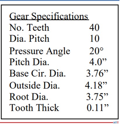
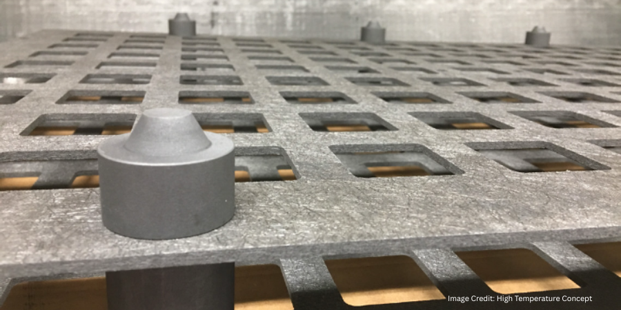
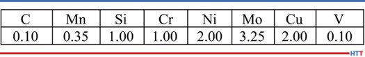
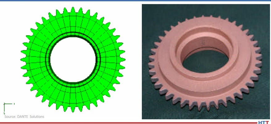
Pyrowear 53 was the material of choice for the project, as it is used extensively in helicopter power transmission gearing. Table 1 lists the nominal alloy chemistry for Pyrowear 53, which is a low-carbon, carburizing grade of steel. Figure 1 shows a CAD model of the test gear (left) and a picture of an actual test gear (right); the actual test gear is copper plated to selectively carburize only the gear teeth. The gears were carburized as one batch, and then hardened and tempered to a tooth surface hardness of 59 HRC and a core hardness of 42 HRC. An oil quenching process was used to harden half of the gears and an Intensive Quenching process was used to harden the other half of the gears. Table 2 lists the dimensional specifications of the gear.
One benefit of using the Intensive Quenching process over a conventional oil quenching process is the development of high residual surface compression. Compressive surface stresses benefit fatigue performance by offsetting any tensile stress generated during loading, effectively reducing, or eliminating, the tensile load experienced by the material. Figure 2 compares the residual stress predicted by DANTE for the test gear subjected to an oil quenching process (top) and an Intensive Quenching process (bottom). It is clear that the Intensive Quenching process induces a greater magnitude of compression in the area of the tooth root, which is the location of most gear bending fatigue failures. The residual stresses present in the tooth flank appear equivalent between the two quenching processes, but the oil quenched component has higher tensile stresses under the carbon case. This could lead to problems should any inclusions or material defects be present in that location.
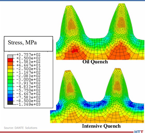
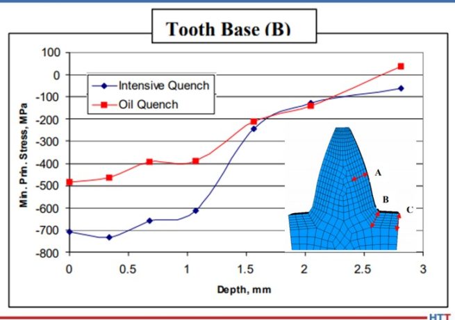
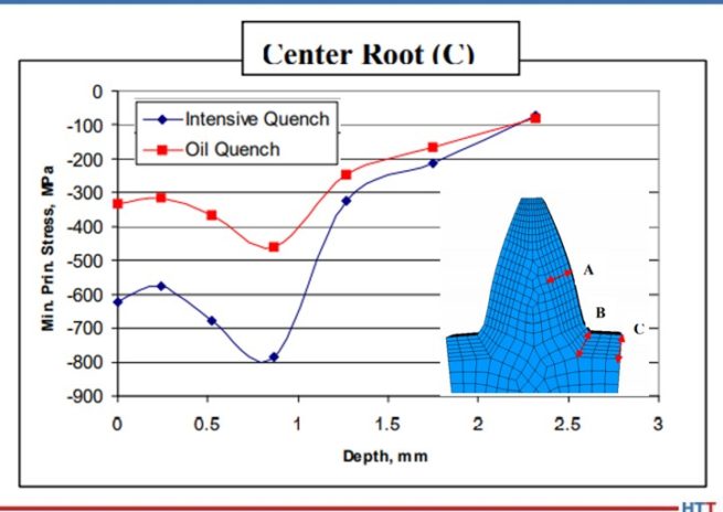
Figures 3 – 5 compare the residual stress profiles of the two gears at three gear tooth locations: flank, root-fillet, and root, respectively. The residual stress profiles for the two processes at the tooth flank, shown in Figure 3, are equivalent, as inferred from the contour plots shown in Figure 2. Both quenching processes generate a surface compressive stress of 275 MPa on the tooth flank. However, the residual stress profiles in the root area of the gear vary greatly between the two processes. Figure 4 shows the residual stress profile at the root-fillet, which is the location of the highest tensile stress during gear service. At this location, the rapid surface cooling afforded by the Intensive Quenching processes creates a large temperature gradient from the surface to the core, allowing more thermal shrinkage to occur after the surface transforms to martensite. The additional thermal shrinkage, combined with the concave geometry of the gear root area, creates additional compressive stresses in this area.
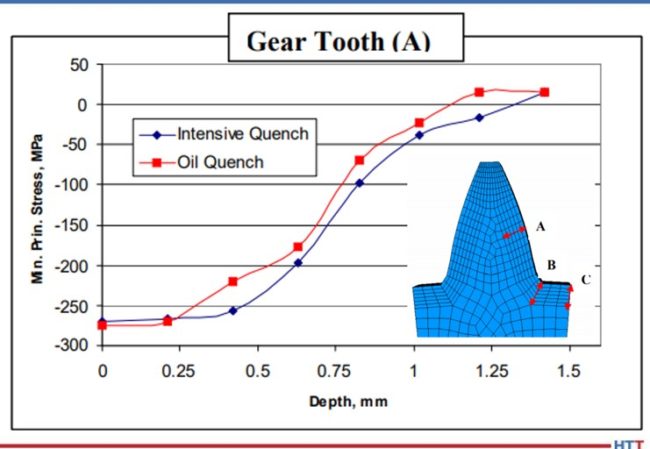
Figure 4 shows that the Intensive Quenching process generated a compressive stress of 700 MPa on the surface of the root-fillet, while the oil quenched gear produced a 500 MPa compressive surface stress in this location. The intensively quenched gear also has a deeper layer of high compression, not rising above 600 MPa compression until after 1 mm below the surface. Figure 5 shows a similar trend for the root, but with an even larger difference between the two quenching processes, since the geometry is even more concave at this location. Again, the gear subjected to the Intensive Quenching process has high compression up to 1 mm under the surface and a compressive surface stress magnitude 300 MPa higher than the oil quenched gear at the root location. The modeling results indicate that the intensively quenched gears should outperform the oil quenched gears in bend fatigue given the increased surface compressive stress present.
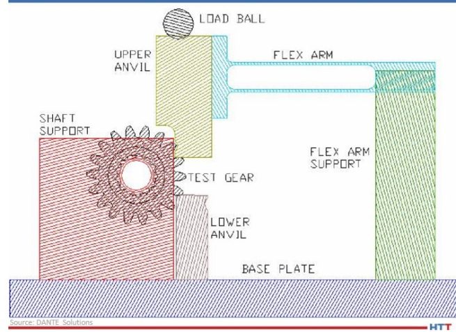
All of the hardened gears were tested at the Gear Research Institute, located at Pennsylvania State University in State College, PA, using a servo-hydraulic testing machine with a specially designed fixture to apply a cyclic bending load to two teeth. A schematic of the fixture is shown in Figure 6. A load ratio of 0.1 was used for all fatigue tests to ensure the gear did not slip during testing by having a constant tensile load applied. The fatigue test was considered successful, defined as a runout, if the gear completed 107 cycles given a certain maximum load. The maximum bending stress, calculated for a stress-free initial condition, was used to compare the two processes.
As previously mentioned, the effect of residual compressive stresses during tensile bend fatigue is to offset the tensile stress generated by the load. Figure 7 shows a DANTE model of the test gear subjected to oil quenching showing the residual stress from heat treatment (top) and the stress redistribution during the application of a 900 lb. load (bottom). Figure 8 shows the same conditions for the test gear subjected to the Intensive Quenching process. As can be seen from the two figures, in which the legend ranges are the same, there is substantially more compressive stress remaining in the root-fillet area of the gear subjected to the Intensive Quenching process when the load is applied. This means the effective stress experienced by the intensively quenched gear is less than that of the oil quenched gear, given an identical load.
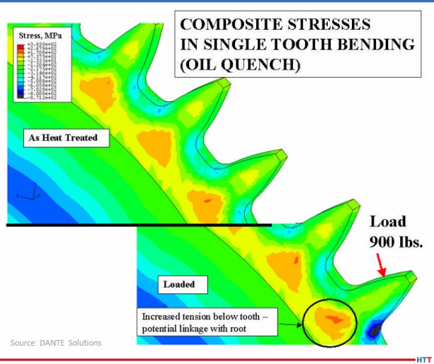
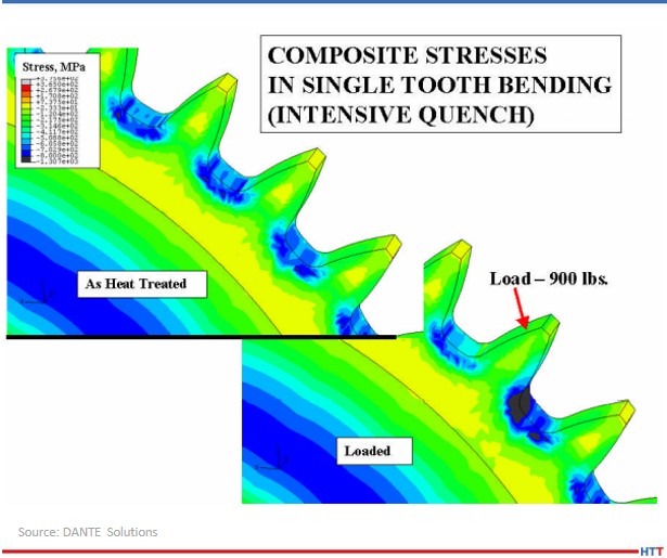
Figure 9 shows the residual stress profile from the surface at the root-fillet for both processes, in the unloaded and loaded conditions. From the plot, a load of 900 lb. generates a tensile stress of approximately 200 MPa, which is offset by the compressive residual stresses. With a 900 lb. load, neither gear sees any tensile stresses during loading, and thus, should runout during fatigue testing.
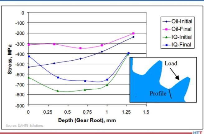
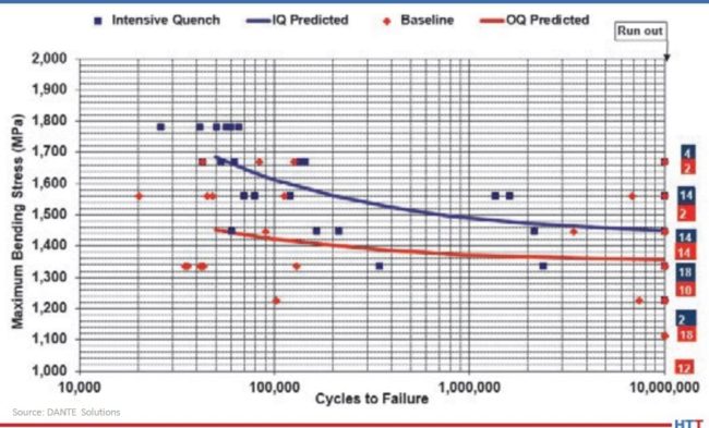
Figure 10 shows the results of the fatigue testing. As expected, the gears subjected to the Intensive Quenching process have an increase in fatigue performance. The endurance limit of the intensively quenched gears is approximately equal to the difference in surface compression, though additional tests should be conducted to confirm this. Regardless, increasing the magnitude of surface compression through a process change can significantly improve fatigue performance of power transmission gearing.
In conclusion, achieving higher residual surface compressive stresses during hardening of a carburized power transmission gear by way of a process change was shown to improve bend fatigue performance. This was confirmed by the company's simulations, which showed a significant increase in compressive surface and near-surface stresses when the gear was quenched using the Intensive Quenching process, as opposed to an oil quench. The cause of the increased compression was determined from simulations to be due to the combination of martensite formation in the surface layers of the gear and the accompanying thermal shrinkage of the austenitic core, which draws concave geometric features, such as a gear tooth root, into a higher state of compression. The large temperature gradient induced during the Intensive Quenching process is necessary to produce these conditions. Physical fatigue testing confirmed the simulation results, showing a significant improvement in fatigue performance for the gears quenched using the Intensive Quenching process. Accurate process simulation pointed to a heat treatment process change that could be used to achieve increased power density through a transmission as opposed to more expensive and time-consuming design changes.
- N. I. Kobasko and V. S. Morganyuk, “Numerical Study of Phase Changes, Current and Residual Stresses in Quenching Parts of Complex Configuration,” Proceedings of the 4th International Congress on Heat Treatment of Materials, Berlin, Germany, 1 (1985), 465-486.
- N. I. Kobasko, “Intensive Steel Quenching Methods. Theory and Technology of Quenching”, SpringerVerlag, New York, N.Y., 1992, 367-389.
- N. I. Kobasko, “Method of Overcoming Self Deformation and Cracking During Quenching of Metal Parts,” Metallovedenie and Termicheskay Obrabotka Metallov (in Russian), 4 (1975), 12-16.
- M. Hernandez et al., Residual Stress Measurements in Forced Convective Quenched Steel Bars by Means of Neutron Diffraction”, Proceedings of the 2nd International Conference on Quenching and the Control of Distortion, ASM, (1996), 203-214.
- M. A. Aronov, N. I. Kobasko, J. A. Powell, J. F. Wallace, and D. Schwam, “Practical Application of the Intensive Quenching Technology for Steel Parts,” Industrial Heating Magazine, April 1999, 59-63.
- A. M. Freborg, B. L. Ferguson, M. A. Aronov, N. I. Kobasko, and J. A. Powell, Intensive Quenching Theory and Application for Imparting High Residual Surface Compressive Stresses in Pressure Vessel Components,” Journal of Pressure Vessel Technology, 125 (2003), 188-194.
- B. L. Ferguson, A. M. Freborg, and G. J. Petrus, “Comparison of Quenching Processes for Hardening a Coil Spring,” Advances in Surface Engineering, Metallurgy, Finishing and Wear, SAE (01) 1373, (2002).
About the Author: Justin Sims has been with DANTE Solutions for eight years and is an excellent analyst and expert modeler of steel heat treat processes using the company's software. His project work includes development, execution, and analysis of carburization, nitriding, and quench hardening simulations. For more information, contact Justin at justin.sims@dante-solutions.com.
All images were provided by DANTE Solutions.