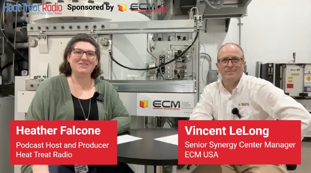
Heat Treat Radio #133: Process Qualification & Recipe Development in Vacuum Carburizing
Heat Treat Radio host Heather Falcone and guest Vincent Lelong, Senior Synergy Center Manager and Metallurgist at ECM USA, explore the realities of process qualification and recipe development in modern heat treating. Vincent shares decades of experience developing vacuum carburizing processes for automotive, aerospace, and high-volume manufacturing applications. Together, they discuss how heat treaters can balance metallurgy, fixturing, quench strategy, and production demands to achieve repeatable results. From practical troubleshooting insights to the evolution of vacuum carburizing technology, this conversation offers a grounded look at what it takes to optimize heat treating.
Below, you can watch the video, listen to the podcast by clicking on the audio play button, or read an edited transcript.


The following transcript has been edited for your reading enjoyment.
Introduction (00:05)
Heather Falcone: Hi, I’m Heather Falcone, and welcome to Heat Treat Radio. Today, we are asking a metallurgist, and we are talking about the ins and outs of process qualification and recipe development. We are on-site with the sponsor of our episode, ECM USA, in beautiful Pleasant Prairie, Wisconsin. It’s a real treat to be able to record on site. We hardly ever get that chance. Joining me today is Vincent Lelong, the Senior Synergy Center Manager and Metallurgist. Thanks for joining me today, Vincent.
Vincent Lelong: Thank you, Heather.
Heather Falcone: So you have the luxury, since we are in your beautiful facility, to tell me not just about yourself, but also about ECM. Start off with your background because it is extensive.
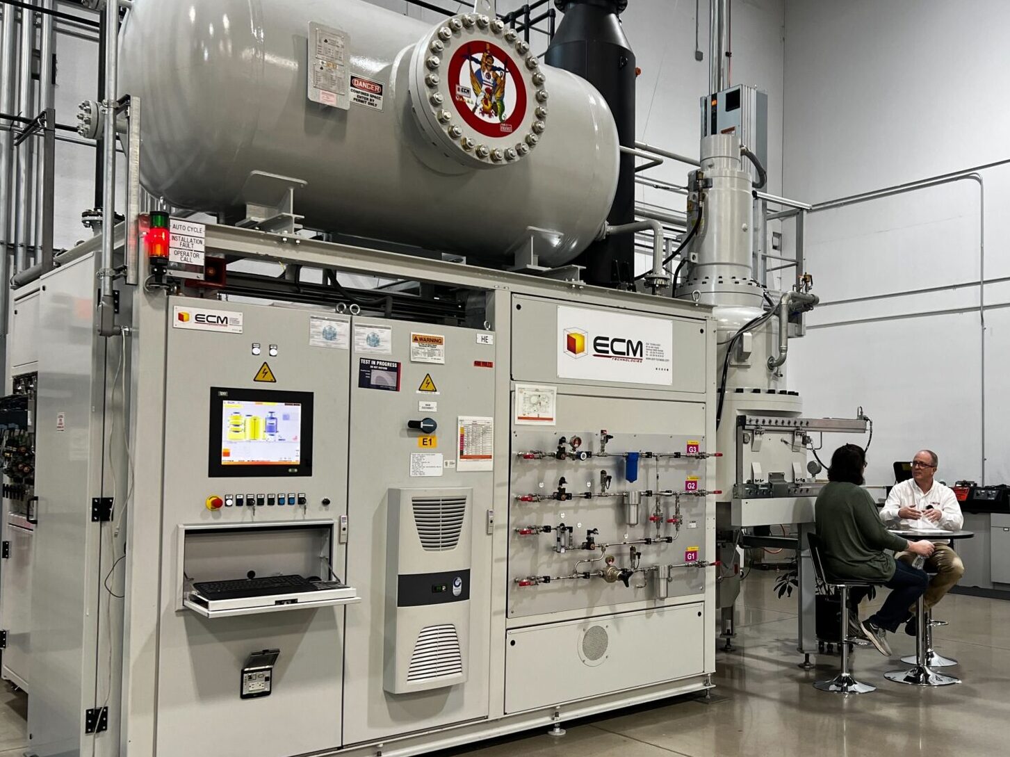
Vincent Lelong: I am a metallurgist, I went to college in France, and I started with ECM in 1999. Since then, I’ve been across the world in the U.S. for 20 years. I do presentation and testing for the furnace behind us and our larger furnace. I go on-site. This is our Synergy Center; it’s a nice environment, clean — quiet today because we’re filming.
Heather Falcone: Tell me a little bit about what ECM does.
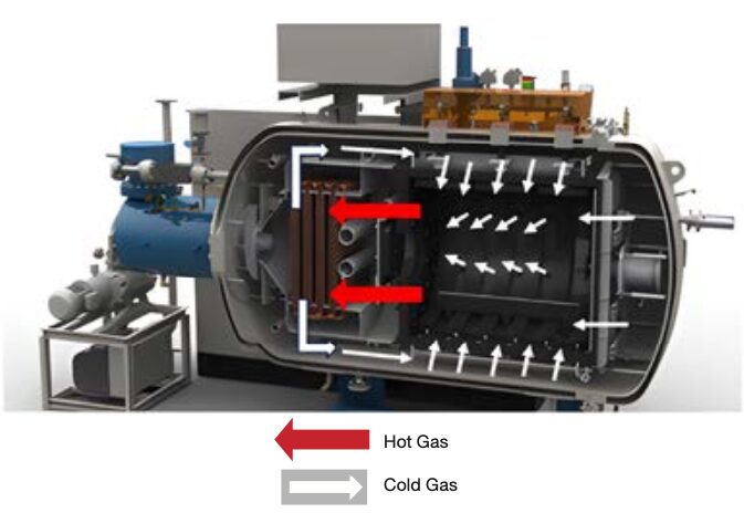
Vincent Lelong: At ECM, we manufacture and install heat treatment vacuum furnaces. Our main focus is on low-pressure carburizing modular furnaces, large and small. We integrate not just heat treatment itself, but the pre-treatment, like washing, storage, preparation of the load with robots, heat treatment, temper, cryo… Everything is set up together, and that is our main goal: integration of a fully automatic installation.
Heather Falcone: A one-stop shop. You go to one place, and you’re going to make it all work.
Vincent Lelong: There’s a part and everything will be ready in few hours later, sometimes days, depending on the treatment.
Heather Falcone: Hopefully it all works.
Vincent Lelong: Well, it always works. It’s a really repeatable modular furnace. In the U.S., we are focusing on vacuum carburizing, but we also manufacture other types of furnaces for crystal growth, silicon heat treatment, melting silicon for solar panel, and others. Within ECM Group, there’s a range of heat treatment processes that we manufacture for. And not just steel; it can be other materials. I’m specialized in steel and very restricted heat treatment with vacuum carburizing, but maybe one day we can do other materials.
Heather Falcone: Steel makes the world run.
Vincent Lelong: With our modular furnace, we can do hardening, gas quench, oil quench, carburizing, gas quench, oil quench, and now we do vacuum carbonitriding and we can do nitriding in the furnace. So you can have one installation for multitask heat treatment. It’s the purpose of the modular furnace, the beauty of it.
Heather Falcone: More flexibility, more capabilities.
Biggest Challenges of Process Qualification and Recipe Development (4:08)
Heather Falcone: That brings us into the first core question that I want to ask, because when you’re evaluating bringing in another piece of equipment or if you’re trying to bring on a new process, it can be a little challenging. What do you see are the biggest pitfalls or what do you see people struggling with most when it comes to process qualification and recipe development?
Vincent Lelong: Most customers say, “I would like a good metallurgy. I would like mechanical properties.”
Heather Falcone: Right, make good parts. That’s number one.
Vincent Lelong: But you need to look at what kind of furnace you would like to use, as well as the size, the type of part, and the process. If you have a small part, do you want a bulk load? Do you want special fixtures because the main target is distortion-free? Everybody would like everything…
Heather Falcone: …distortion-free!
Vincent Lelong: Always. No problem. So, as a metallurgist, you need to think not just about heat treatment because you’ve been asked to heat treat a part. I could heat and quench in oil and say, “You have the metallurgy. My job is done.”
Heather Falcone: Right. It hit hardness.
Vincent Lelong: Exactly. Hardness, good. Vacuum carburizing, no oxidation. Good. How about the distortion? Okay, let’s speak about what we can do to reduce the power of the heat treatment itself. Then, let’s do a gas quench, but let’s work on fixtures also. It’s working with the supplier for fixtures and working with the customer with the machinists.

Sometimes, because we propose gas quench, people say, “Oh, gas quench means no distortion.” Well, the first step is to get the metallurgy right. If you need 20 bar gas quench, you might have some distortion. From experience, we know that the fixtures are also important. So we can work with the customer and supplier to propose the right fixtures and test the fixtures to target the best cooling rate and other properties.
But we also need to work with the machinists. If you have a challenging part, machinists may say, “It’s the fault of the metallurgist.” And the heat treater will say, “No, let’s work together at the table. We’ll sit, and we do the testing.” At the Synergy Center we have also the CMM, so we can measure before heat treatment and after heat treatment. It’s the best feeling when you bring not just the metallurgists together, but also the people who make the part. We work together to have the best of the best. It’s a lot of work, but we have years of experience, so we can reach the target faster than 20 years ago.
Technology has changed. As such, you also need to work with the steel manufacturer, the way the steel is made and the composition. Research has shown that if you improve the steel, you can reduce the quench pressure. If you need oil quench, then you already know that distortion will be potentially higher. If you need 20 bar, it’s one thing. Well, I did a presentation not long ago, and I found that the distortion with 10 bar or 20 bar in a Nano furnace was much better than in a larger load. For one part, that is. This might not be true if it’s other parts. There’s always that phrase in heat treatment, “that depends.” I don’t like this phrase.
Heather Falcone: It always depends.
Vincent Lelong: But it’s true, unfortunately. So, when you have worked all that together, you can bring the best analysis. I’m working before that to sell a furnace.
I need to choose whether it’s better for the customer to have a smaller furnace or a larger installation. That really depends on how many parts, the diversity of parts. If the customer has mostly small parts, the Nano may be the better choice. You have a faster answer because it’s in and out. You don’t need to buy so many fixtures. But if you have a larger part, a larger furnace is better. It’s not whether one furnace is better than the other. You need to choose which one will achieve your production target.
A customer in facility number A may need a larger furnace, but in facility B, there are other types of part, so that facility may need a smaller furnace. That’s how we work with the customer to target what is important.
Heather Falcone: Pick the right atmosphere, pick the right hot zone size, pick the right fixturing, raw material specs. All of those are going to influence how the runs going to go. I bet you have some stories about TCE from fixturing and eutectic and inadvertent bonding.
Vincent Lelong: I certainly have had a few mistakes in testing. I used a higher temperature because with vacuum carburizing we say we can go to a higher temperature. But then I used CFC fixtures at the wrong temperature!
Today however, the mixtures of fixtures can work and reduce the weight. As a metallurgist and a heat treater, I prefer to heat treat the part rather than the fixtures. When I see a customer running a load with almost more fixtures than parts, I’m asking, “What do you heat treat?” Are you losing money on heat treating fixtures more than parts?”
Heather Falcone: There is such a big weight differential between fixturing and the parts. How much lag time on your heat up and cool down are you wasting on having too much fixturing?
Vincent Lelong: It’s true.
Balancing Technical Requirements with Production (11:30)
Heather Falcone: Once you’re in recipe development, how do you balance technical requirements, the repeatability, and the realities of production?
Vincent Lelong: Repeatability is firstly about how you design the load. Then you need to know the quantity of parts. You also may know the surface of your load, but it may always be necessary, I will say. Most of the time we don’t know that and it still runs correctly.
Heather Falcone: Still a black box. It’s an art what we do.
Vincent Lelong: Technically, it’s a good thing because when we put something inside the furnace, it’s coming back, and we don’t see much difference. But the mechanical properties are completely different, so it is kind of like magic.
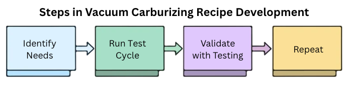
So you define your load, you define your heating time to get temperature, and when you’re sure you’re at temperature, you start to carburize. I will speak about vacuum carburizing. First, we have software for the carburizing boost and diffusion; you input your parameters and then you have your recipe. You can run it generic, or you can go into detail and improve it. But as built, the software will give you some set parameters and will work.
Heather Falcone: Technology is so cool.
Vincent Lelong: It’s getting better and better. You will also need to select the type of furnace. When you have one part, it’s not the same as when you have 3,000 parts. The density of the load will influence your gas flow and the capacity of your installation.
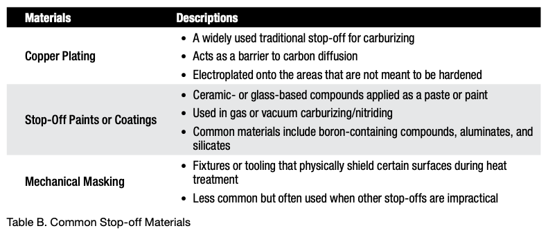
Most of our larger furnaces have a maximum of acetylene of 4,000 liters. But you can play with the gas and the duration of the boost and diffusion so it goes inside the part; when you have a blind hole or you need 3 millimeters, you carburize. (Acetylene is beautiful, but molecules can go everywhere, sometimes where we don’t want acetylene, which is why we have the stop off.) But you define your load, you define your recipe, your gas flow, and then you run a test and analyze the metallurgy. If it’s good, then you’re done and you don’t move from that.
Heather Falcone: That’s what production wants to hear.
Vincent Lelong: When you are a heat treater, you may receive 10 parts to heat treat. Tomorrow you may receive 20 parts, and maybe you need to run the same recipe. In general, you can run the same recipe for 10 parts or 20 parts. You would use the parameters of the larger load for the smaller, if possible. The result will be mostly the same, but the cost will not be the same.
This is where you can optimize your recipe for different types of load, like half of the load versus a full load. You can change the flow of gas, and then reduce your heating time because why set for two hours when in one hour, it is at temperature. One hour is money.
Heather Falcone: Got to turn and burn.
Vincent Lelong: This is also where you define your database and your repeatability. I once had a customer that had me create a recipe for a specific quantity of parts and a design of load. A few years later, that customer called and said, “It doesn’t work.” With modern heat treating controls, we record everything, so you have a database, the curves, and you can go back and see what was wrong.
Heather Falcone: Right. What changed?
Vincent Lelong: In this case, I discovered the customer was running the double quantity of parts in the same load without changing the recipe at all.
Heather Falcone: Makes sense. Start there.
Vincent Lelong: Heating time was not long enough. Gas flow was not long enough. And they were not working at the right pressure in the furnace, so failure occurred. I said, “Change that.” No news is good news usually. If the customer doesn’t call you, it’s because…
Heather Falcone: …Everything works.
Vincent Lelong: That’s the beauty of this furnace.
With repeatability, you always need to look at the curves. If you have an issue of temperature out of the range, there will be an alarm. So, you can check if the part is good without checking the metallurgy. If you heat treat a big part, usually you won’t cut the part. If you have six parts in a load or 10, you have samples. You have to validate your sample and your real part at the beginning.
Heather Falcone: To make sure it’s representative.
Vincent Lelong: Exactly, or if there are differences because you cannot find exactly the same material, you know the difference, and the difference would be always the same.
Heather Falcone: Right. Make it predictable.
Vincent Lelong: We have some customers that would check one load per day or per shift and not every load. If you have 3,000 parts in a load, you can check a part. When you have six parts, you will likely not cut a part. If the furnace tells you it’s good, why check? When you check repeatability, you still need a lab. Not checking the metallurgy is difficult. You should always check again. Repeatability shouldn’t be left to chance or statistics. Take a part and check. Is it good? Then continue.
Heather Falcone: That’s kind of the target of qualification, right? To get those parameters that you predefined.
Vincent Lelong: In time you need to be sure nothing changes.

Heather Falcone: What does re-qualifying look like?
Vincent Lelong: You want to be sure that nothing changes, material-wise. Sometimes, you run the same material, and you achieve 35 HRC. But at one point in time, you achieved only 25 HRC. This is the same material on the paper, but something has happened. So you need to go back in time and figure out what was originally going on. Is it the heat treatment? Is the installation of something around it?
Heather Falcone: Use all the data that’s available to you.
Vincent Lelong: This is where you check the productivity.
Quench Media (19:20)
Heather Falcone: How about the quench media?
Vincent Lelong: When you develop a recipe, if you do oil quenching you will always do austenitizing. You don’t want a crack. You will carburize, austenitize, and go to oil quench. It’s pretty easy to switch from atmosphere oil quench to vacuum oil quench because technically the recipe is pretty much the same, and we’re going to cover that ground extensively because I know it’s kind of scary to even consider that possibility.
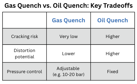
When you go with gas quench, if you don’t know the target or are unsure, you select 20 bar.
Heather Falcone: Sure, 20 bar. That’s the easiest in the world.
Vincent Lelong: Exactly. You do 20 bar and you get what you get. There is an advantage of the gas quench. Many customers will ask, “Do I need to do a direct quench? Do I need to do austenitizing?” Most of the time we say direct quench, and we found that you don’t crack with gas quench. Whatever the pressure, we never really have much cracking. Or a customer may ask, “Will the part break due to the gas quench?” That will never happen. I once asked the competition if they ever saw a crack with gas quenching and they said no. It’s the way the gas quench quenches and cools the part down, then it’s less powerful than the liquid, so you don’t have this potential issue.
But if you don’t know, you stay at 20 bar. If you would like to optimize, you can reduce, but you need to achieve the target metallurgy.
Heather Falcone: Right. You’ve got to get your core hardness.
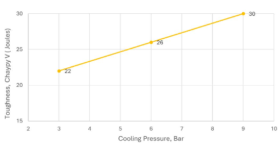
Vincent Lelong: Your limit is when your metallurgy is not right. When you reduce, you reduce the cost. If you reduce the pressure and the speed, you will reduce the distortion potential.
Heather Falcone: Which is always a good thing.
Vincent Lelong: If you have a shaft, you should not place it horizontal, because whenever you quench that, it will not be straight.
Heather Falcone: We’ve potato chipped a few parts over the years, yes.
Vincent Lelong: Me too. I have tried horizontal in some cases. It’s interesting, but you need more support. I think it’s possible, but nobody wants to try it.
Heather Falcone: Why bother?
Vincent Lelong: Vertical is easier.
Heather Falcone: If you’re qualifying, just make the fixture that’s going to support it.
Vincent Lelong: Yes. Why should I change? It’s always a big question; we just quench it vertically this way. We do it this way. Now for gears, in heat treat sites I see a lot of vertical positions for gears strung on a rod. As an operator, I don’t like that.
Heather Falcone: Tell me why.
Vincent Lelong: Because it’s heavy. We already have difficulty finding operators in heat treatment. If it’s heavy, nobody wants to do it.
From a robotic point of view, it’s more difficult, too. Today, with most vacuum carburized and gas quenched gears are heat treated horizontally on fixtures and most of the time with offset position. That will give you the best metallurgy, but also the least distortion overall. Vertically for machinists, it’s very difficult to re-machine something round to oval. When you place it horizontally, you can do potato chips but machinists can grind and reshape the part easily, if it’s possible.
Heather Falcone: If you’re already near net, it’s going to be a different story.
Vincent Lelong: Exactly. That’s where when you check your distortion and repeatability of process — it’s the fixtures.
Heather Falcone: I would think working with the customer as much as you can to see if material can be left on the part too, if we do need to have grinding, if we do need to have repair or recovery for any possible distortion.
Vincent Lelong: So, let’s say we are working on a six-speed. For the six-speed, everybody wants to vacuum carburizing gas quench. The objective: zero distortion, heat treat, and assemble.
Heather Falcone: In theory.
Vincent Lelong: No, in truth.
Heather Falcone: Really? Okay.
Vincent Lelong: That was the target.
Heather Falcone: Ambitious, I like it.
Vincent Lelong: Yes, but when you have a new product, you can use new technology, you can work on the fixtures, you can work on everything. We worked a lot with car manufacturers to do the best heat treatment, the best fixtures, the maximum of parts, of course, and repeatability. This furnace is running millions of parts.
That is why we know vacuum carburizing works and it’s repeatable. For this high volume, we had to work on zero distortion. But the specification then didn’t change, metallurgically speaking. Most of the time it was 0.3 to 0.7 millimeters. It’s a large gap. No problem. Then we went to the 10-speed for most of the automotive, and then the distortion was the target because of the experience we gained with the six-speed, which was the noise. People don’t want the noise. Today, with the 10-speed, we start to grind at 0.1 millimeter.
You have to compensate for your carburizing process so that it is longer and deeper, but also most customers will reduce the metallurgical requirements. From 0.3 to 0.7, they want 0.5 plus or minus 0.05, which is much thinner. With electrical applications today, you want zero noise, because you can hear everything. There’s a lot of grinding, and when I say a lot, I mean exact, 0.2 millimeter.
Heather Falcone: That is a lot of post-process work.
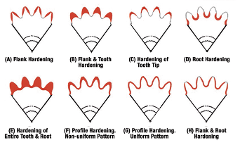
Vincent Lelong: You have the perfect teeth. You need to anticipate longer carburizing, and it’s great! Also, what I see with metallurgy, it’s not that you don’t have a general metallurgical specification, but each area of a part will have its own metallurgy. That means you have the pitch of the gear, the roots, a minimum, but sometimes you have a specification of the tip.
A customer may specify, “I don’t want more than 0.8.”
Heather Falcone: Just for that area.
Vincent Lelong: Yes. As the parts get more and more complex, they have more than just one application or function. You have the spline. You have double teeth. Each one will have its own requirement. With an atmospheric furnace, to get that, it doesn’t work very well. But with vacuum carburizing, you can achieve very precise requirements.
Switching from Atmospheric to Vacuum Carburizing (28:11)
Heather Falcone: To that point, is that one of the things that stops people from considering the change from atmospheric to vacuum carburizing, or is it part complexity?
Vincent Lelong: The larger companies do not seem to be afraid, because they know what they want and they already have experience. For the heat treaters, the smaller companies, it’s very difficult to switch with the requirements today. When you see the requirement on the drawing, it’s funny because before there was just heat treatment.
Heather Falcone: Yeah, it’s on this process sheet.
Vincent Lelong: One line. Surface condition, effective case depth, core hardness.
Heather Falcone: Right.
Vincent Lelong: Today there are different requirements, and there are several requirements: before heat treatment, after, and final. You know how much you need to take off, and not every area you take off. You said keep more material. The advantage of that is more material, less distortion. But you will have to carburize more.
Heather Falcone: Ultimately it may be more expensive for everybody.
Vincent Lelong: Exactly. The machining behind the grinding is also costly. When we develop a recipe, we have the customer machine to the final dimension, do the heat treatment, and then we will see where we are in terms of metallurgy and distortion. If we are not where we need to be, don’t take off too much. Then you adjust.
One other story is about a thread.
Heather Falcone: Oh, God, threads. The bane of every heat treater’s existence, threads.
Vincent Lelong: I get a lot of questions about threads. Do I need to make them before heat treatment? Do I need to put a mask on, paint, or make the fixture?
Heather Falcone: Fixture or mechanical.
Vincent Lelong: Or to not do them and do them after?
Heather Falcone: That is also expensive.
Vincent Lelong: Yes, also expensive; but I think it could be a robotic application.
Heather Falcone: Oh true. Very good point.
Vincent Lelong: It’s the way I would go.
Heather Falcone: How interesting.
Vincent Lelong: To not do the thread before.
Heather Falcone: Lower risk.
Vincent Lelong: First, when you carburize, you can create a brittleness of the thread. But also operator movement of the thread from crate to the fixtures can cause damage to the thread. What do you do? Can you save the thread after heat treatment? Not always. Then that is garbage. You had to manufacture the part, heat treat the part, just to put in the garbage, which is a cost.
Heather Falcone: Probably 80 or 90% of your whole cost, gone in an instant.
Vincent Lelong: In my opinion, you could have a robot preparing the load. You would have a robot take off, and every time it’s the same movement. Then, thread or not, it’s easier.
Heather Falcone: More predictable.
Vincent Lelong: Then the robot, if you don’t do the thread, can put the shaft, usually it’s a shaft with a right connection on the thread on the end, put to a little induction machine, reheat, and then put in a crate and go back to machining. Then it’s all done.
In that instance, I think it’s my preference not to do the thread first. I have customers who ask me for paint or for a mask. Paint is not, I would say, 100% safe. You need a specialist to put on the paint. There are some tricks, as I know heat treaters know. They have been doing this for years and they know their stuff.
Heather Falcone: That’s their secret.
Vincent Lelong: I think heat treaters have more secrets about painting and protection of the part than the big companies do. They know it better.
Heather Falcone: Their lives are on the line. That’s all they do, so they have to make it perfect.
Vincent Lelong: You can learn a lot from heat treaters. They know their work.
Heather Falcone: That’s what I always recommend to the captives. Get out to as many heat treat shops as you can, because it’s going to make your in-house heat treat better.
Vincent Lelong: They have years of experience to learn from. Heat treatment is tricks after tricks. Some customers are afraid to go to in-house heat treatment. These heat treaters hold a variety of information that is helpful for these customers.

Heather Falcone: It’s an interesting point that you brought up about being afraid, because vacuum carburizing has gotten that reputation over the years that it’s difficult. It’s tough to figure out.
Vincent Lelong: Because we did a good job. We did a good job to say you can optimize. In reality, if you understand what you want to heat treat, the carburizing process is all made by software. Every company has their own software. So it is pretty simple, and though it can still be scary for the heat treater.
Heather Falcone: Process change is scary.
Vincent Lelong: There are some companies that develop vacuum carburizing software where you need to know everything about the steel, the chemistry, all the parameters. We work with carbon. For our software, you enter the carbon content originally, roughly the temperature you would like to heat treat, and what you would like on the final. The software will give you something, and it will be 95% of what you’re looking for.
Now you need to quench. Like I said, with oil quenching, it’s no problem. Gas quenching, 20 bar, no problem, very easy and straightforward. Optimization can be where it’s trickier. But it’s just like an atmospheric furnace. I work with atmospheric furnaces, and they all have their cheat sheets.
You need carbon potential, temperature, time, and in vacuum carburizing, it’s the same thing. The temperature, your carbon potential, or what you expect for carbon, the time, the case depth you would like to achieve, and here is your process.
Heather Falcone: Then you don’t need the cheat sheet. It’s gone. Then it’s documented and repeatable.
Vincent Lelong: Right, then you have to heat up and quench. So, straight heat treatment: heat it up to be sure you’re at temperature, then carburize, and you quench.
Heather Falcone: One test?
Vincent Lelong: Yes, I often do just one test.
Customers may ask me to do a test for a Flex system, a larger system. I do it here at the Synergy Center first because it’s cheaper for me because it just value add and it’s here. I can mix a different part, different design, and run. “Oh, it’s a 8620? No problem.” Usually, it’s good.
For a Nano load, it’s like a one-fifth or it’s a one fixture and the bigger load, it’s like two column of fixtures, then you stack. So, it’s not much different. You start on a smaller scale and you go bigger, and you just add a little heat up time.
And if you ask me, “What do you need?” Put everything to the maximum!! (We are here to sell you a spare part, so, you know.) But really, if you put everything to the maximum you will be good. Maybe too good, and you might have a more maintenance, but we’d be able to provide a quote to reduce the maintenance. (*joking laughter*)
Closing Thoughts (37:36)
Heather Falcone: As we finish up, if there’s one thing that you’d want our listeners to take away, rethinking about their approach to process qualification and recipe development, what do you want them to know?
Vincent Lelong: It’s not difficult. It’s like every other heat treatment; you have to test it and you will quickly see that it’s easy. At ECM USA, we provide training and testing to show you what can be achieved and answer your questions. If you’re worried, we will show you how easy it is, how clean it is. There’s no flame. If you have oil quench, there’s no flame because everything is protected. So it’s not difficult, it’s just one step. Do not be afraid.
Heather Falcone: Take that first step, and explore the process.
Vincent Lelong: I think there’s enough research and evidence in the last 25 years in the U.S., especially with large automotive and aerospace companies to know that it’s not a big deal. Most people — in heat treating or not — don’t like change.
Heather Falcone: But they can partner with you, Vincent, who has decades of experience. Reach out to ECM. Get in touch. Start exploring.
Vincent Lelong: The funny thing is, with decades of experience, what we are capable of heat treating 20 years ago we can do way better now. The technology is better. Gas quenching is made to quench, not to cool. It’s quenching. It’s hard. It’s almost as hard of a quench as an oil quench. You can do bulk load carburizing. I did carbonitriding in bulk load not that long ago. If you had asked me to do that 20 years ago, I would say, “No way that works.” But today that works. Just contact us.
Heather Falcone: Start the conversation, right?
Vincent Lelong: And I would be happy to show you. I like my job.
Heather Falcone: You love your job. I’m going to say it. You’re very passionate.
Vincent Lelong: I like testing because it’s a challenge every day. It’s pushing the limit. It’s like a movie. Is it possible? If you follow the book or internet, they will say no. I would say, “Let’s try.” I’m testing on materials other than steel as well that I would not have expected to work. Modular furnaces can be a very versatile.

Heather Falcone: Well it sounds like production is getting ready to get things done. Thanks so much, Vincent. It was great spending time with you.
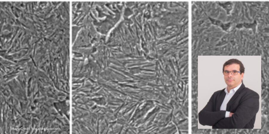
About the Guest
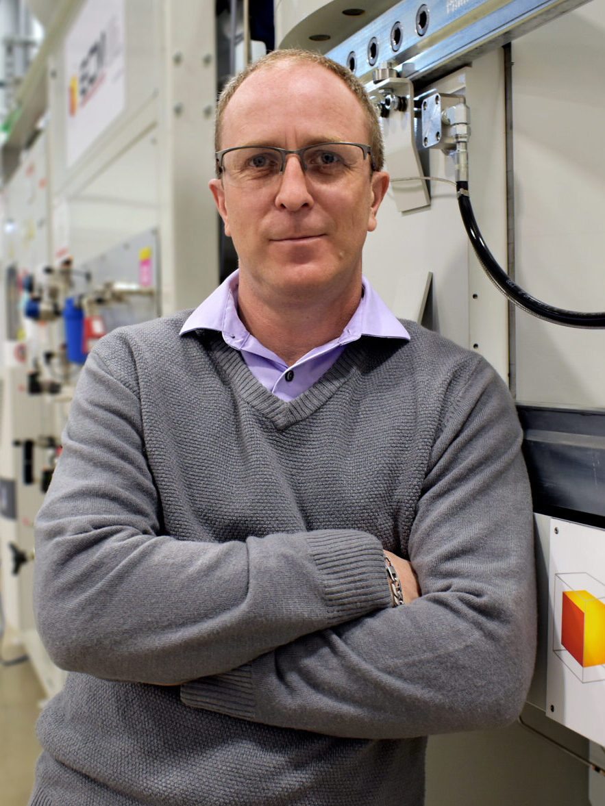
Synergy Center Manager / Sr. Metallurgist
ECM USA, INC.
Vincent Lelong, ECM USA Synergy Center Manager, transferred to ECM USA in 2005 to manage the North American Testing Program in Wisconsin after 6 years’ experience with production/testing furnaces at ECM Technologies headquarters in Grenoble, France. Vincent has degrees in Chemistry & Physics from the University of Reims, and Treatment of Materials (specializing in Heat Treatment) from BTS Roosevelt, also located in Reims, France. He began his career as a production and laboratory technician for a commercial heat treater, and joined the ECM Group in 1999 as an ECM Technician running LPC testing/metallurgical analysis within ECM vacuum furnace systems.
For more information: Contact Vincent Lelong at vincentlelong@ecm-usa.com.

Heat Treat Radio #133: Process Qualification & Recipe Development in Vacuum Carburizing Read More »