![]() What do helicopter gears and heat treat modeling have to do with improving the bend fatigue performance of low-alloy gear steels? Find the answer in this interesting case study which analyzes the effects on compressive surface stress caused by changing the heat treating process.
What do helicopter gears and heat treat modeling have to do with improving the bend fatigue performance of low-alloy gear steels? Find the answer in this interesting case study which analyzes the effects on compressive surface stress caused by changing the heat treating process.
This Technical Tuesday is provided by Justin Sims of DANTE Solutions and was featured in the Heat Treat Today's 2021 March Aerospace print edition. Check out more original content articles in this digital edition or other editions here.
Introduction
Lead Engineer
DANTE Solutions
Helicopter powertrain gearing can be subjected to tremendous loads during service. The high tensile loads experienced in the root of the gear tooth, combined with the cyclic loading conditions inherent in gear operation, can lead to cyclic bend fatigue failures. To improve cyclic bend fatigue performance, low-alloy steels are often carburized and quenched. The combination of a high carbon case and low carbon core leads to increased strength and hardness in the carburized case, while maintaining a tough core. In this manner, the case resists wear and can carry a high load without fracture, while the core is able to absorb the energy imparted to it during operation.
Besides the increased strength and hardness, the addition of carbon creates a chemical gradient from the surface of the component towards the core. The carbon gradient creates delayed martensite transformations relative to the low carbon in the core and is responsible for imparting residual compressive surface stress. A compressive surface stress can benefit bend fatigue performance by reducing the mean stress experienced during service, effectively offsetting the tensile stress generated by the cyclic loading conditions.
Most gear steels contain enough alloying elements to guarantee a transformation to martensite upon quenching to room temperature from the austenite phase field. It is well known that the martensite starting temperature is significantly influenced by the amount of carbon in austenite at the time of transformation, with higher amounts of carbon generally lowering the martensite start temperature. This means the chemical gradient present after carburizing creates a nonuniform phase transformation, with the transformation starting at the base carbon just below the carburized case and progressing inward toward the core.
As the martensite is formed, the atomic rearrangement results in a volume expansion, causing a tensile stress to form on the surface as the core material pushes out on the surface. As the component continues to cool, the martensite start temperature is reached in the carbon rich case, usually well after the core has transformed to martensite or bainite, depending on the cooling rate. The transformation in the case progresses outward, with the surface being the last to transform. This core-to-surface transformation results in a compressive surface stress since the volumetric expansion created by the martensite transformation at the surface is constrained by the core material.
Because the timing of the transformation to martensite is the main driver in the generation of compressive residual surface stresses, it is possible, to some extent, to control the magnitude of the surface stress by changing the quenching process. Historically, transmission gears have been carburized and quenched in oil. However, as more attention is paid to improving part performance through processing techniques, other forms of quenching have become available that show promise in increasing surface compressive stresses, and thereby improving bend fatigue performance. Of particular interest is a quenching method which utilizes high pressure, high velocity water to quench parts.
Known as Intensive Quenching®, the method was developed by Dr. Nikolai Kobasko as an alternative means of quenching components to achieve deep residual surface compression and improve bend fatigue performance.1-3 The technology works by inducing a large temperature gradient from the surface to the core of the component. In non-carburized components, the process has been shown to provide an extremely rapid and uniform transformation to martensite in the surface layers, while the core remains austenitic. This creates a hard shell under extreme compression. As the part continues to cool, the surface is pulled into an even deeper state of compression. As the core transforms, some compression is lost due to the expanding core, but the compression that remains is generally greater than that achieved by oil quenching. 4 – 7
To evaluate the possibility of improving bend fatigue of helicopter transmission gears, a program was conceived to compare the bend fatigue performance of carburized gears quenched in oil versus carburized gears quenched using the Intensive Quenching process. Funded by the U.S. Army, the project was comprised of two phases. Phase One was a proof-of-concept phase, designed to prove that intensively quenched components could outperform oil quenched components in high cycle bend fatigue testing. Phase Two then moved to actual transmission gear testing. DANTE Solutions Inc. heat treatment modeling was used extensively throughout the project to guide processing decisions and understand the mechanisms responsible for improved bend fatigue performance through the creation of residual surface compression. This article will explore Phase one, with Phase two covered in a follow up article.
Phase One
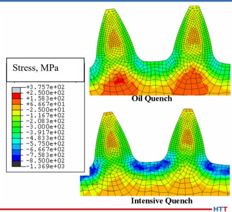
Before any testing was initiated, the company heat treatment simulation was executed to compare the residual stress induced in a gear tooth root from oil quenching and Intensive Quenching. As can be seen in Figure 1, using Intensive Quenching significantly increased the near surface residual compression. This increase in compression should result in an increase in bend fatigue performance. Satisfied with these preliminary results, a testing regiment was initiated.
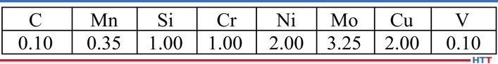
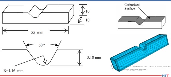
The steel alloy Pyrowear® 53 was chosen as the candidate material for this project. Table 1 shows the base chemistry of Pyrowear 53. The alloy is used extensively in the aerospace industry as a transmission gear material due to its ability to resist softening at high temperature in the hard carburized case, while maintaining high core impact strength and fracture toughness. A specially designed “V” notch 3-point bend fatigue sample was created by the company in conjunction with input from experts at the Army Gear Research Lab at NASA-Glenn and Bell Helicopter. The design was chosen to mimic behavior of a gear tooth root during loading. Figure 2 shows the dimensions of the coupon, the selectively carburized surface, and the finite element model used to explore the effects of process parameter changes on residual stress.

A total of 40 coupons were manufactured and selectively carburized. The coupons were then split into two groups. Both groups were subjected to the same 1674°F (912°C) austenitizing, - 110°F (-79°C) cryogenic treatment, and double temper at 450°F (232°C). However, the two groups differ in the method of quenching, with one group quenched using the standard oil quenching practice for Pyrowear 53 and the second group quenched using the Intensive Quenching method. The two groups were processed separately. The Intensive Quenching unit utilized in this project uses a high velocity water stream to quench one component at a time. Figure 3 shows the coupon orientation within the intensive quenching unit. The blue arrow indicates the direction of water flow over the coupon.
After processing all of the coupons and modeling the two processes using the same heat treatment simulation software, a comparison was made between the two processes and the simulation. Figure 4 shows the hardness profile comparison at the center of the notch. As seen, the hardness profiles are equivalent between the two processes. This is expected as the carbon and other alloy content in the material is identical between the two processes. The simulation also matches the experimental data well. While the hardness profiles are identical between the two processes, the residual stress profiles at the center of the notch are not the same, as shown in Figure 5. The intensively quenched coupon has a surface compressive stress of 800 MPa, more than double the compression induced by oil quenching. However, at 0.4 mm, the profiles converge. This is significant as the surface can now carry a higher load, yet no detrimental effects are seen subsurface. Again, the simulation matches the experimental results well.
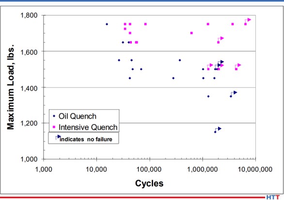
Satisfied with the increased surface compressive stress gained through the use of Intensive Quenching, 3-point bend fatigue testing was initiated at Case Western Reserve University. Load control was applied, with a minimum to maximum load ratio of 0.1 used to maintain a state of cyclic tension. This type of loading ensures the sample remains stationary throughout the duration of the test.
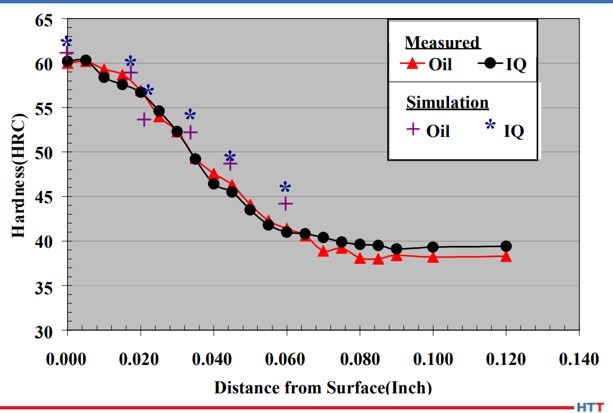
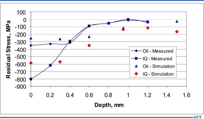
Figure 6 shows the results of the bend fatigue testing. It appears from Figure 6 that the increased residual surface compression of the intensively quenched coupons contributed to an increase in bend fatigue performance when compared to the oil quenched samples. However, some scatter does exist. Several parameters could have influenced these results.
First, during coupon manufacturing, the notch was created in the coupon using a milling operation and then heat treated. After heat treatment, no finishing operation was performed on the notch. Therefore, the possibility of surface defects existed. Any surface defect can create a stress riser, creating a stress condition which exceeds the expected stress given the loading conditions and geometry. However, surface defects would not be consistent coupon to coupon, and therefore have the potential to skew fatigue results.
The second parameter that could have influenced the scatter in the fatigue results is related to the intensive quenching process itself. The process is dependent on a steep temperature gradient to generate the greatest level of compressive stress. This requires high velocity water to impact the component quickly, as any delay or low velocity water impingement can create shallow temperature gradients. Using the DANTE software, it was determined that in order to generate the greatest amount of surface compression, full flow must be achieved in a maximum of one second. This was a significant discovery that may have gone unnoticed if simulation was not used to explore process parameter sensitivities. It was unclear if the equipment operation met this maximum time restraint during processing of all coupons. However, due diligence was given to system operation in future experiments with improved consistency.
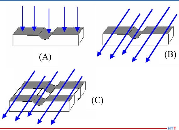
Another processing parameter that has the potential to influence residual stress generated during an intensive quenching operation is the orientation of certain geometric features relative to the high velocity water flow. Again, the DANTE software was utilized, in lieu of expensive physical testing, to determine the optimum orientation of the fatigue sample in the intensive quenching unit. Figure 7 shows the three orientations evaluated. The orientation in Figure 7(A) has the water impinging on the notch surface and Figure 7(B) has the water impinging on the side of the coupon, with water flowing parallel to the notch. Recall that the original coupon orientation, shown in Figure 3, has the water impinging on the top of the coupon and flowing perpendicular to the notch. The final configuration, shown in Figure 7(C), places two coupons in the chamber side-by-side. This configuration has the potential to create an even steeper thermal gradient within the coupon due to the two coupons sharing thermal energy from being in contact with one another, and thus having a slower cooling rate in the core than a single coupon.
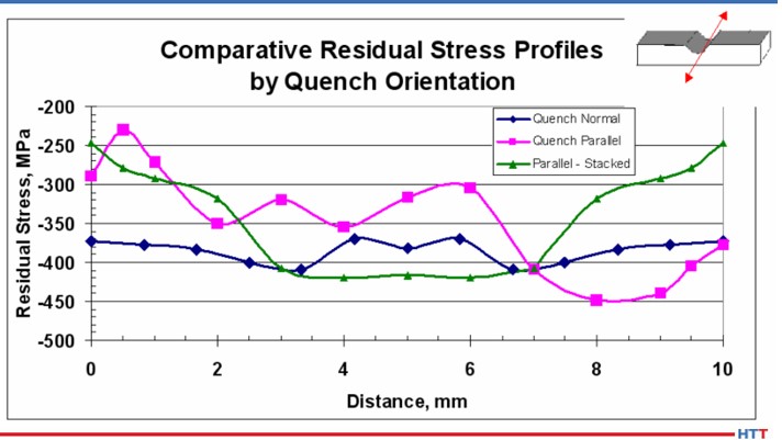
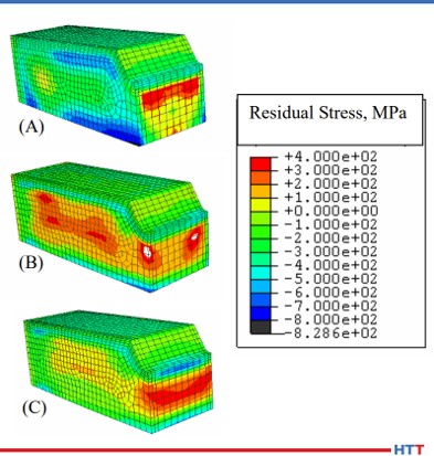
Figure 8 shows the surface residual stress across the width of the notch center, as shown by the red arrow in the Figure 8 inset, for the three orientations predicted by the simulation. Of the three orientations evaluated, orientation (A) resulted in the greatest magnitude of compression, as well as remaining the most consistent across the width of the notch. The residual stress contour plots of the three orientations, shown in Figure 9, confirm the uniformity of the residual stress profile across the width of the notch for orientation (A). The other two orientations show markedly reduced compressive surface stress near the edges of the notch. This type of profile would most likely fail in fatigue at those locations with reduced surface compression. To achieve the most consistent performance results, the most uniform surface condition should be sought.
The residual stress profiles at the center of the notch are shown in Figure 10 for oil quenched coupons, intensively quenched coupons with orientations (A) (“IQ-face”) and orientation (B) (“IQ-side”), and the company simulation results for the three processes. As predicted by simulation, and confirmed by X-ray diffraction measurements, the intensively quenched coupon in orientation (A) results in the highest magnitude of residual surface compressive stress, as well as having the deepest compression. The measurements also revealed that intensively quenching the coupon geometry in orientation (B) results in a slight increase in surface compression, when compared to oil quenching, but the compression is reduced much quicker in the orientation (B) coupon. Based on the simulation results, it was surmised that orientation (A) would outperform orientation (B) in bend fatigue, and oil quench would outperform orientation (B). Due to the poor residual stress distribution predicted for orientation (C), no coupons were processed in this orientation.
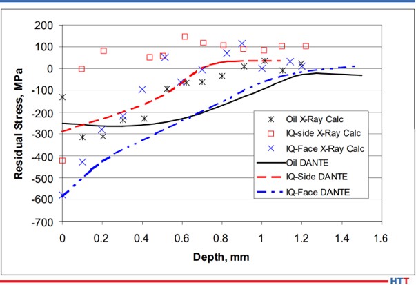
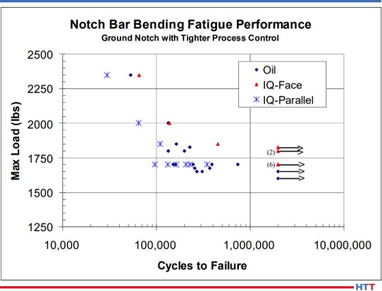
Figure 11 shows the bend fatigue results for the oil quenched coupons and the intensively quenched coupons in orientation (A) (“IQ-Face”) and orientation (B) (“IQ-Parallel”). As predicted from information gleaned from the DANTE simulation, orientation (A) outperformed the oil quenched coupons. The orientation (A) coupon recorded an endurance limit of approximately 1800 MPa, while the oil quenched coupons recorded an endurance limit of approximately 1600 MPa. This difference is approximately equal to the difference in near surface compressive stress induced by the two processes. The orientation (B) coupons failed to successfully complete a test at the loads chosen. Convinced that increasing the magnitude of surface compression through a process change could improve fatigue performance in transmission gears, Phase Two was initiated to evaluate the process change on an actual gear component.
Conclusion
In conclusion, a project was launched to use heat treatment modeling, in conjunction with physical testing, to determine the effects of a process change designed to induce a greater magnitude of compressive surface stress to improve bend fatigue performance of a low-alloy gear steel. Pyrowear 53 was chosen as the gear steel and Intensive Quenching was chosen as the process change to induce a greater magnitude of residual surface compressive stress. Before any testing was initiated, DANTE modeling was used to show that intensive quenching could indeed produce a greater magnitude of surface compression, possibly improving bend fatigue performance by introducing a compressive mean stress and lowering the actual stress witnessed by the component. This modeling was also used to determine the maximum amount of time which may be used by the intensive quenching equipment to reach a full flow condition and still produce an increase in residual surface compression, as well as evaluate the residual stress profile of several different intensive quenching orientations.
Using this modeling to direct physical testing, hardness, residual stress, and bend fatigue performance were evaluated in coupons quenched in oil and coupons intensively quenched in three different orientations. The fourth orientation was not tested as modeling showed the residual stress profile to be unfavorable. Physical testing confirmed the modeling results: hardness profiles are equivalent between the processes, and residual stress profiles coincide with modeling results. Bend fatigue performance was indeed increased by increasing the magnitude of surface compressive stress. Phase One of the project showed that bend fatigue performance was improved by increasing the magnitude of the part’s surface compressive stress and demonstrated that modeling can be an invaluable tool when evaluating process parameter changes on material performance.
References
1. N. I. Kobasko and V. S. Morganyuk, “Numerical Study of Phase Changes, Current and Residual Stresses in Quenching Parts of Complex Configuration,” Proceedings of the 4th International Congress on Heat Treatment of Materials, Berlin, Germany, 1 (1985), 465-486.
2. N. I. Kobasko, “Intensive Steel Quenching Methods. Theory and Technology of Quenching”, SpringerVerlag, New York, N.Y., 1992, 367-389.
3. N. I. Kobasko, “Method of Overcoming Self Deformation and Cracking During Quenching of Metal Parts,” Metallovedenie and Termicheskay Obrabotka Metallov (in Russian), 4 (1975), 12-16.
4. M. Hernandez et al., Residual Stress Measurements in Forced Convective Quenched Steel Bars by Means of Neutron Diffraction”, Proceedings of the 2nd International Conference on Quenching and the Control of Distortion, ASM, (1996), 203-214.
5. M. A. Aronov, N. I. Kobasko, J. A. Powell, J. F. Wallace, and D. Schwam, “Practical Application of the Intensive Quenching Technology for Steel Parts,” Industrial Heating Magazine, April 1999, 59-63.
6. A. M. Freborg, B. L. Ferguson, M. A. Aronov, N. I. Kobasko, and J. A. Powell, Intensive Quenching Theory and Application for Imparting High Residual Surface Compressive Stresses in Pressure Vessel Components,” Journal of Pressure Vessel Technology, 125 (2003), 188-194.
7. B. L. Ferguson, A. M. Freborg, and G. J. Petrus, “Comparison of Quenching Processes for Hardening a Coil Spring,” Advances in Surface Engineering, Metallurgy, Finishing and Wear, SAE (01) 1373, (2002).
About the Author: Justin Sims has been with DANTE Solutions for eight years and is an excellent analyst and expert modeler of steel heat treat processes using the DANTE software. His project work includes development, execution, and analysis of carburization, nitriding, and quench hardening simulations. He has developed the DANTE HELP packages and is the primary trainer and software support person for the DANTE software.
All photos provided by DANTE Solutions.