Jim Roberts of U.S. Ignition engages readers in a Combustion Corner column about the basics of heat transfer — breaking down the First Law of Thermodynamics into practical terms for heat treaters, then using a real-world example to show how ambient load temperature can meaningfully shift BTU energy requirements and furnace performance.
This column was first released in Heat Treat Today’sJuly 2026 Annual Super Brands Issue print edition.
A furnace guy walks into a heat treat plant and says to the group of operators, “I just transferred here.” One of the furnace operators says, “Perfect, it’s what we do best.” Huh…? Well, of course they transfer heat. That’s what heat treaters do better than anyone else — we transfer heat. And the science of this transfer is called thermodynamics.
In the world of physics, there are four laws of thermodynamics, which are centered on the movement and flow of heat between objects. We’ll start with the concept of heat transfer, based on the First Law of Thermodynamics.
The concept of thermal conservation states that energy cannot be created or destroyed; it can only be transferred or transformed. In other words, whatever we put into the furnace in the form of heat will be the same amount that comes out or is absorbed. Additionally, the part we want to heat treat has thermal mass and therefore has heat as well. We say that the load is “cold,” but really, it’s normally coming into the process at room temperature, which means there is energy there that gives us a head start in heating it up.
Then, we know that the heat we feel from the shell of the furnace was not absorbed by the load but is part of the energy that we put into the furnace, it just wasn’t absorbed by the load. So, the heat exits the furnace into the room to be absorbed by other items that are not in equilibrium. The energy is always there, continuing on. It’s a wild concept, isn’t it?
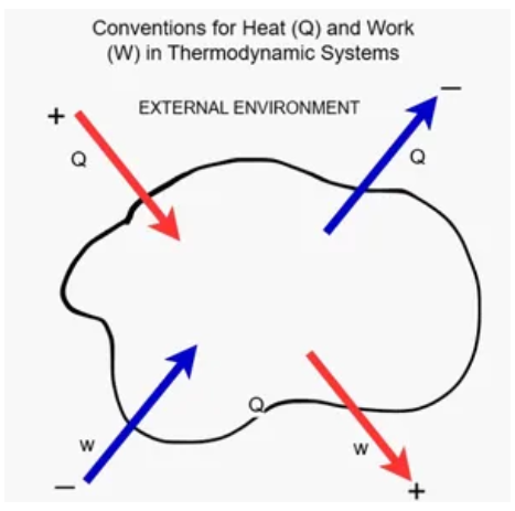
Figure 1. The First Law of Thermodynamics | Image Credit: Jim Roberts
As shown in Figure 1, heat enters the furnace (designation “Q”). Heat then enters the work, which is designation “W” (e.g., load, furnace). Work absorbs most of the heat, but it also releases energy since it is starting to go towards a state of equilibrium, meaning heat in and heat released are equal. Then, the work releases energy into the area where it is not as hot and tries to heat it up and gain equilibrium. That’s the furnace guy standing there, the room, the building, etc. All of these things become the next stage of “work.”
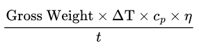
So, when we get to the point of calculating the input (energy usage), we generally use BTU or KW ratings. We also must consider ambient temperature of the work because that Delta T, or temperature variance, is what we are having to account for. If that load is sitting at 70°F, it has value as a heat source, so we need to account for that. You will recall that the formula that is commonly used for calculating heat load is:
This will give you BTU requirements after you then apply an efficiency. Sometimes that’s an estimated efficiency. Let’s show the difference in that energy requirement that needs to be provided when the latent heat in the load is different.
Let’s suppose we are a heat treater in central Michigan. It’s December. We have been accustomed to staging our bulk parts for heat treating out on our open loading dock. The furnace is suddenly not performing like it did earlier in the year. It’s the same 1,000 lb load. Earlier in the year, our formula accounted for the 70°F load temperature coming in. Our equation would be:
In this example, if we bring the work in from the frozen loading dock at 20°F, the heat required jumps to 401,231 BTU energy required per hour. It’s not a lot, but the furnace will notice and not perform as well since the burners tend to run at a fixed setting.
Even slight variations can make a big difference in cost and performance. Simple and yet slightly confusing science is behind it all.
About The Author:
Jim Roberts President US Ignition
Jim Roberts president at U.S. Ignition, began his 45-year career in the burner and heat recovery industry focused on heat treating specifically in 1979. He worked for and helped start up WB Combustion in Hales Corners, Wisconsin. In 1985 he joined Eclipse Engineering in Rockford, IL, specializing in heat treating-related combustion equipment/burners. Inducted into the American Gas Association’s Hall of Flame for service in training gas company field managers, Jim is a former president of MTI and has contributed to countless seminars on fuel reduction and combustion-related practices.
Ask The Heat Treat Doctor® has returned to bring sage advice to Heat Treat Today readers and to answer your questions about heat treating, brazing, sintering, and other types of thermal treatments as well as questions on metallurgy, equipment, and process-related issues. In this installment, Dan Herring explores the heat tint colors that form on stainless steel during heating and cooling — how the surface oxide layer thickens and shifts through straw, bronze, peacock, and blue hues at specific temperatures — and explains the factors, such as chromium content, oxygen levels, time, and surface roughness, that influence how and when these colors appear.
This informative piece was first released in Heat Treat Today’sJune 2026 Sixth Annual Buyers Guide Issue print edition.
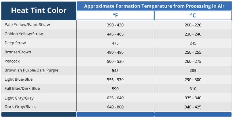
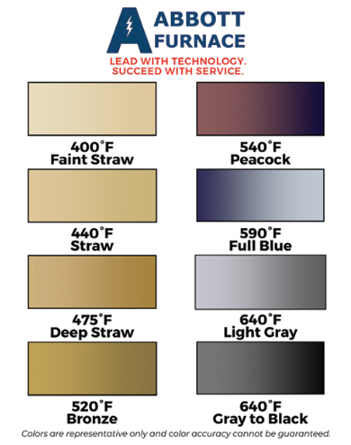
Most heat treaters, engineers, and clients are familiar with temper colors on steels (Herring 2014, ASM International 1991) and often assume that these color tints (hues) are the same for stainless steels (Table A). However, there are subtle changes that are worth noting. Let’s learn more.
Table A. Heat Tint Color Chart for Stainless Steels | Source: The HERRING GROUP, Inc.
The Science Behind Heat Tint Colors
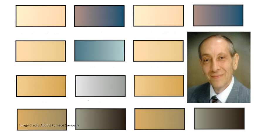
Figure 1. Examples of color tints | Image Credit: Abbott Furnace Company
When stainless steel is exposed to an air atmosphere, or a high dew point moisture-laden atmosphere during heating or cooling, its surface changes color; that is, a thin oxide layer forms on the surface (Figure 1). This heat tint color (aka temper color) is caused by a progressive thickening of the surface oxide layer.
As most of us know, an invisible (aka passive) layer occurs naturally on stainless steels. It is extremely thin, typically in the order of 1 to 3 nanometers (3.93 x 10⁻⁸ to 1.18 x 10⁻⁷ inches) thick.
Upon exposure to air during heating or holding at temperature, this oxide layer grows in thickness. When it is approximately 20–30 nanometers (7.87 x 10⁻⁷ inches) thick, it starts to become visible to the human eye as a light-yellow or straw yellow color tint.
As the oxide layer becomes even thicker it transitions from almost transparent to a variety of different colors (e.g., bronze, peacock, blue).
As the oxide layer thickness increases from 20 nm to roughly 50–100 nm (1.97 x 10⁻⁶ to 3.94 x 10⁻⁶ inches), the colors deepen changing to a golden yellow, to a deep straw, to a bronze or golden brown, to peacock (a purplish-blue), to full blue, then light gray, and finally dark gray.
Above 100 nm (3.94 x 10⁻⁶ inches,) up to approximately 850 nm (3.35 x 10⁻⁵ inches) the tint transitions from dark blue/gray to black.
Such shallow oxides are known to enhance corrosion resistance on various stainless steel grades.
Factors Influencing Color Change
Several factors influence the type of oxide that forms on the surface, its adhesion to the surface, and how quickly the thickness of the oxide will grow (BSSA).
Chromium
From a purely material standpoint, the single most important element is the chromium (Cr) content of the stainless steel. To be classified as a stainless steel, it must contain a minimum of 10.5–11% Cr. The higher the chromium content, not only is the alloy more heat resistant, but the heat tint color formation mechanism is retarded.
Oxygen Content
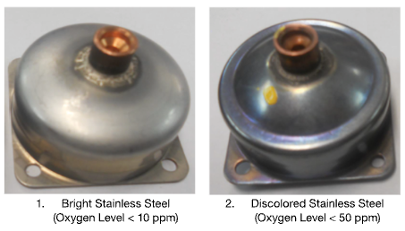
Figure 2. Bright and discolored stainless steel parts run in a continuous brazing furnace. The discolored part was caused by room air infiltrating into the cooling zone at high levels (> 50 ppm) from the exit of the furnace. | Image Credit: The HERRING GROUP, Inc.
Another factor that influences the rate of oxide formation and the thickness of the oxide is the oxygen content of the atmosphere (Figure 2). Air is approximately 21% oxygen. Nitrogen, however, will typically have between 0.001%–1% oxygen depending on its source, while argon typically has between 0.0005%–1% oxygen. By contrast, water vapor contains around 89% oxygen.
As anyone who has run stainless steel in vacuum furnaces knows, stainless parts can be discolored due to such factors as an air leak during heating or cooling, a pinhole water leak in a heat exchanger which opens during cooling in one temperature range and close again at a lower temperature, or air infiltration in the backfill gas supply.
Time
Time plays a factor as well. The longer the exposure time, the deeper the heat tint color.
Surface Roughness
Finally, surface roughness influences both the rate of oxidation and the heat tint color formation. Rougher surfaces tend to oxidize at a higher rate and with all other factors remaining the same, deeper colors are produced.
Final Thoughts
Knowing the color tints that may form on the surface of stainless steel is invaluable in helping the heat treater explain this phenomenon to their clients and/or troubleshoot their equipment and processes in an attempt to minimize or eliminate undesirable surface tints on the stainless steel parts that they run.
References
Herring, Daniel H. 2014. Atmosphere Heat Treatment, Volume I (Section 5.8). BNP Media Group II.
British Stainless Steel Association (BSSA). bssa.org.uk.
About the Author
Dan Herring “The Heat Treat Doctor” The HERRING GROUP, Inc.
Dan Herring has been in the industry for over 50 years and has gained vast experience in fields that include materials science, engineering, metallurgy, new product research, and many other areas. He is the author of six books and over 700 technical articles.
In this installment of Technical Tuesday, Jim Roberts of U.S. Ignition engages readers in a Combustion Corner editorial about the role of velocity in heat treating — breaking down how faster burner speeds create more turbulence in the furnace, which helps parts heat up faster and more evenly.
This editorial was first released in Heat Treat Today’sJune 2026 6th Annual Buyers Guide Issue print edition.
A furnace guy walks into a heat treat plant and looks around. While it all looks calm and controlled, the agitation inside the furnaces is rampant.
So many times, we forget to slow down, look over our shoulders, and see all we’ve accomplished or learned. Combustion Corner series began with the intent to take a simple, almost primer-level look at what combustion-related issues the modern heat treater — furnace technicians, production managers, and really everybody involved in the process — may encounter.
The focus has been on burners and flame-related items. Occasionally, we get questions for an opinion on considering gas-fired versus electric furnaces or other similar questions. That’s dangerous ground to tread because so many different processes can use both. In fact in most cases, the method of heating is really moot to the process goal: Get heat delivered, cleanly, and all will be well with the parts and the process.
With that in mind, let’s take a peek at what really matters in heat treating. It’s the heat. Specifically, it’s how to get heat delivered as quickly as possible and with as much control as is possible. I know, kind of obvious that heat is important in heat treating. There are “four modes of heat transfer,” but we’ll just look at one of them today.
Convective Transfer
Convective transfer is an easy one because we see so many practical applications in our own homes. The new ovens in the modern home are often convection ovens and seemingly everybody has an air fryer. In the kitchen alone, you can see this how heat transfer increases can happen via convection increases. Take this principle to the shop floor and you can see how critical it is in processes that allow contact with flue gases or hot air.
We used to heat up the box of bricks, and once it got to the needed temperature for the metallurgy requirement, we would push in a basket of parts and wait for them to catch up to that temperature. The thermal mass of the load would literally suck the heat right out of the box, and the temperature would crash. Then, we’d wait for the temperature to stabilize. Once there, the old rules of time and temperature would apply.
But what if we wanted to speed up the process? What if we wanted more even temperature delivery and more temperature uniformity? The word that comes to mind in most burner intrinsic processes is velocity.
Velocity
We talked about how some direct-fired burners are now designed to give fantastic exit velocities from the burner and into the furnace chamber. And when I say fantastic, it has to do with comparing what was an acceptable burner design back in the early days of industrial America when burner flame/flue gas exit velocity of direct-fired heat treating was like 40 MPH. New burners of today have exit velocities of almost 500 MPH!
Here is why it matters: Velocity will have a direct effect on the heat transfer, firstly by blasting into the “boundary layer” of gases that circulate around parts in the furnace. And most flue gases have been laminar in nature, but with this increased turbulence, the agitation of these gases allows more direct contact with the actual part.
The Reynolds Number
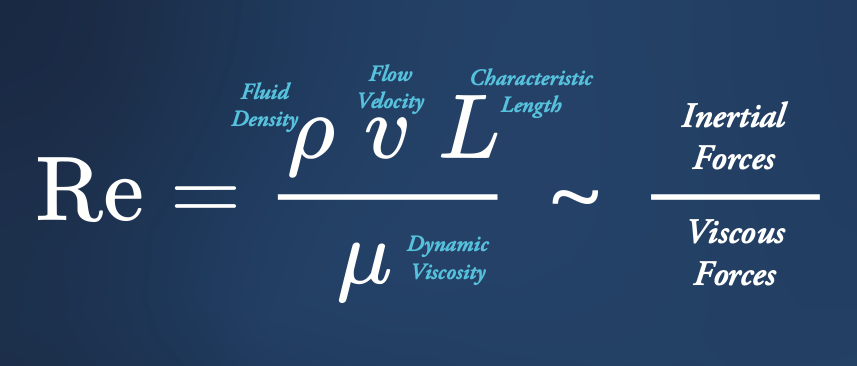
This increased turbulence results in a higher Reynolds number. The Reynolds number (Re) is a dimensionless quantity in fluid mechanics that predicts flow patterns — laminar (smooth) or turbulent (chaotic) — by calculating the ratio of inertial forces to viscous forces.
The word viscous reminds us that all things flowing around in the furnace are considered fluid from a scientific viewpoint. Interestingly, all this turbulence also results in greater mass transport. Remembering that the part or load has some mass, once it begins to heat up, it actually begins to emit heat as well. This mass transport mechanism is a result of the turbulence moving the heated molecules away from the surface of the part more quickly, which maintains a higher temperature differential, and again, increases heat transfer.
I guess what we are doing here is starting with velocity on a burner-level discussion, and we will discuss multiple methods and scientific quirks regarding the big picture — heat transfer. We will discuss some of the basics of heat transfer and explore comparisons between conduction, radiation, and convection, and more.
Till next time…
About The Author:
Jim Roberts President US Ignition
Jim Roberts president at U.S. Ignition, began his 45-year career in the burner and heat recovery industry focused on heat treating specifically in 1979. He worked for and helped start up WB Combustion in Hales Corners, Wisconsin. In 1985 he joined Eclipse Engineering in Rockford, IL, specializing in heat treating-related combustion equipment/burners. Inducted into the American Gas Association’s Hall of Flame for service in training gas company field managers, Jim is a former president of MTI and has contributed to countless seminars on fuel reduction and combustion-related practices.
In this installment of Answers in the Atmosphere, David (Dave) Wolff, an independent expert focusing on industrial atmospheres for heat treat applications, examines the cost dynamics of hydrogen as a process gas and the blended atmospheres strategies thermal processors use to manage them. Drawing on insights from Stephen Feldbauer PhD of Abbott Furnace, Wolff walks through the key gas blend options available to operators and how operators select the most cost-effective mix for the job.
This informative piecewas first released in Heat Treat Today’sMay 2026 Sustainable Heat Treat Technologies print edition.
In last month’s column, we discussed hydrogen as a process gas and addressed key attributes. In that column and in the one that follows, Stephen Feldbauer PhD, director of Research & Development at Abbott Furnace, provided key insights.
A Question of Cost
Stephen Feldbauer PhD Director of Research & Development Abbott Furnace
Hydrogen gas is relatively expensive; in fact, case studies conducted by Abbott Furnace have demonstrated that atmosphere costs often constitute over two-thirds of the variable costs of thermal processing. Hence, cost savings in hydrogen-containing atmosphere supply are important.
As a result, thermal processors will preferentially employ gas blends, containing just the right amount of hydrogen to get the job done, diluted in a larger volume of inert or non-problematic diluent gas. Think of it like using a small amount of powerful dish soap diluted with a large volume of water to effectively clean a large amount of pots and pans. The primary advantage to using hydrogen-blended atmospheres is that they are much less expensive than using pure hydrogen.
Hydrogen-Nitrogen Blended
Pure hydrogen, delivered or generated on-site, may be blended with pure nitrogen to reduce atmosphere costs. While nitrogen can be delivered as a gas or liquid, it can also be separated from atmospheric air on-site at low cost to produce a hydrogen-nitrogen blended atmosphere. Hydrogen-nitrogen blended atmospheres typically range in hydrogen content from about 3% to 75% hydrogen, with the balance nitrogen. Nitrogen costs the thermal processor about 20% of the cost of hydrogen for a similar volume of gas, so blending hydrogen with nitrogen may be a useful approach to obtaining the benefits of a hydrogen-based atmosphere at substantially lower cost.
The actual blend of hydrogen and nitrogen used is primarily determined by the metal that is being thermally processed. As the oxide of one metal may be more stable and difficult to reduce than another, the amount of hydrogen is often increased to make the atmosphere more active. Some metals will be adversely affected by nitrogen at high temperatures. Thermal processors using a hydrogen-nitrogen atmosphere will use furnace atmosphere mixers to blend the leanest (lowest hydrogen) atmosphere that yields acceptable results in the finished metal parts.
Image Credit: Abbott Furnace
A widely used generation approach to a hydrogen-nitrogen atmosphere is to use a thermal catalytic reactor (a “dissociator”) to crack metallurgical grade ammonia (NH₃) to a gas blend of nominal 75% hydrogen, 25% nitrogen (based on the ratio of nitrogen and hydrogen atoms in the ammonia starting gas). Because ammonia is a commonly used agricultural and industrial chemical, ammonia is widely available and cost-effective. Ammonia is delivered by truck in pressurized liquid form and stored in a tank for use.
The resulting atmosphere gas blend is generally called dissociated ammonia (DA). Significantly less expensive than using pure hydrogen, DA gas is a popular gas blend if a nitrogen-containing gas blend can be used. If decreased reducing potential is acceptable, generated DA gas can be further diluted with pure nitrogen to reduce costs even more.
Generation from Hydrocarbon
Another approach to cost-reducing hydrogen-containing atmospheres is to generate a hydrogen-containing atmosphere from a readily available hydrocarbon, such as natural gas, propane, or even methanol. This is possible because these hydrocarbons can be thermally cracked using a catalytic reactor to liberate free molecular hydrogen gas in a blend with other constituents. These reactors may use partial combustion in the case of Exothermic reactors to make Exo gas, or they may use pure thermal cracking, avoiding combustion, in which case the technique is called Endothermic gas generation, and the resulting gas is often called Endo gas.
Because Exo gas is a result of partial combustion with air, an Exo gas blend has approximately 10% hydrogen and considerable nitrogen in it, whereas Endo gas has approximately 40% hydrogen and very low levels of nitrogen. Because both Exo and Endo gases contain considerable carbon (originating from the fuel gas), their uses are limited to processes and materials where the carbon content does not create processing issues.
Argon-Hydrogen Blend
Many of the stainless steel grades cannot be thermally processed in nitrogen-containing atmospheres because the nitrogen gas will react with the chromium, damaging the alloy. In that case, an argon-hydrogen blend may be employed. Because argon is more expensive than hydrogen, the economics of an argon-hydrogen gas blend may result in much higher levels of hydrogen in the furnace atmosphere.
About The Author:
David (Dave) Wolff Industrial Gas Professional Wolff Engineering
Dave Wolff has over 40 years of project engineering, industrial gas generation and application engineering, marketing, and sales experience. Dave holds a degree in engineering science from Dartmouth College. Currently, he consults in the areas of industrial gas and chemical new product development and commercial introduction, as well as market development and selling practices.
In this installment of Answers in the Atmosphere, David (Dave) Wolff, an independent expert focusing on industrial atmospheres for heat treat applications, examines the powerful reducing properties and high thermal conductivity that make hydrogen a critical atmosphere in metal thermal processing.
This informative piece on hydrogen’s role in sintering, annealing, and surface protection — including how it is sourced, how it behaves inside the furnace, and how operations can safely manage this flammable atmosphere under NFPA 86 —was first released in Heat Treat Today’sApril 2026 Annual Induction Heating & Melting print edition.
Hydrogen is widely used in metal thermal processing for sintering of powdered metal fabrication technologies and for heat treatment (e.g., annealing, brazing) of bulk metal manufactured components. This column draws heavily from an interview the author had with Stephen Feldbauer Ph.D., director of Research & Development at Abbott Furnace. Abbott Furnace is a leading furnace manufacturer for continuous furnaces and furnace controls. As R&D Director, Steve leads Abbott’s work in pioneering furnace advances with a special focus on debinding and sintering.
Why Hydrogen?
Stephen Feldbauer, PhD Director of Research & Development Abbott Furnace
Hydrogen provides two desirable characteristics to heat treaters: very high chemical reducing potential and the highest thermal conductivity of any gas. The high reducing potential enables hydrogen to convert heated metal oxide coatings to pure metals. This is extremely helpful for successful sintering of powder metallurgical parts. Superior thermal conductivity enables rapid part heat up and cool down. Compared with either vacuum or inert gas atmospheres, hydrogen enables much faster throughput and achieves shorter furnace cycles.
Hydrogen-containing atmospheres are required to successfully sinter most iron-based metal parts, whether manufactured by powder metallurgy (PM), metal injection molding (MIM), or binder-jet metal additive manufacturing techniques. As-received, the iron-containing metal powders used for these advanced fabrication techniques are covered with an iron-oxide coating, making it virtually impossible to successfully sinter the particles together under reasonable temperature conditions. Reducing the oxide coating enables successful sintering.
Hydrogen-based atmospheres used with a tube or strand furnace are the primary surface protective technology used for drawn components (e.g., wire, tubing, and profiles). Hydrogen simultaneously protects the part surface from oxidation and allows metal to anneal, which softens it and restores toughness after it has been hardened by the drawing process.
Sourcing Hydrogen
Because of its high reactivity, hydrogen is almost never found in nature as a pure gas (H2). Instead, it is generally found as a component in a compound like water (H2O) or a hydrocarbon gas or liquid, such as methane (CH4), propane (C3H8), or longer hydrocarbon. In order to be used as a thermal processing atmosphere, hydrogen is liberated from these hydrogen-containing compounds to exist as a pure gas while in use in the hot furnace.
The liberation of elemental hydrogen from its compound carrier can happen at a remote plant operated by an industrial gas company provider, in which case the hydrogen would be compressed or liquified for delivery to the thermal treatment client, or may be conducted at the site of the thermal processor themselves through use of on-site generation equipment. User choices of approaches to pure hydrogen supply will be covered in future columns.
Inside the Furnace
Inside the hot furnace, hydrogen changes metal oxide coatings to pure metals by preferentially reacting with the metal oxides to produce pure metal and water vapor. Thus, the furnace atmosphere dewpoint (a measure of gaseous water content) will increase as the hydrogen simultaneously creates pure metal surfaces and produces water vapor as a byproduct. The water vapor is swept out of the furnace and replaced by the clean furnace atmosphere that flows counter current to the heated metal product. Furnace atmosphere controls for hydrogen-based atmospheres use dewpoint as a key operating parameter.
Hydrogen’s ability to protect the part surface from oxidation is critical in the annealing process. | Image Credit: Abbott Furnace
Since furnaces must open to admit parts for thermal processing, the furnace, the atmosphere system, and the procedures must all be designed to prevent unsafe conditions caused by hydrogen leaking out of the furnace, or air leaking in. Furnaces intended for a flammable gas atmosphere use doors, curtains, and pilot lights (i.e., flame curtains) to prevent hydrogen or other flammable gas from leaving the furnace without being combusted. These precautions avoid explosions inside or outside the furnace.
Furnaces for hydrogen-containing atmospheres utilize unique design and construction approaches to safely use this flammable atmosphere. In the U.S., furnace design and operation is guided by NFPA 86, the furnace code. NFPA 86 defines certain furnace design features and also defines standard operating techniques for safe operation with a combustible atmosphere, such as a hydrogen-containing atmosphere. Similar codes and standards are used in other countries.
Next month, this column will pick up the question of cost by looking at options for generation of hydrogen atmosphere blends. Generation of pure hydrogen will be a future topic.
About The Author:
David (Dave) Wolff Industrial Gas Professional Wolff Engineering
Dave Wolff has over 40 years of project engineering, industrial gas generation and application engineering, marketing, and sales experience. Dave holds a degree in engineering science from Dartmouth College. Currently, he consults in the areas of industrial gas and chemical new product development and commercial introduction, as well as market development and selling practices.
Jim Roberts of U.S. Ignition engages readers in a Combustion Corner editorial about keeping industrial burners in tune — examining how everything from simple orifice plates to sophisticated burner control units (BCUs) and P-type radiant tubes drive efficiency and temperature uniformity in modern heat treating furnaces.
This editorial was first released in Heat Treat Today’sApril 2026 Annual Induction Heating & Melting print edition.
In part 2 of this series (Aerospace Heat Treating, March 2026), we talked about how balancing the pressure can save gas and reduce emissions. So, how do they do it?
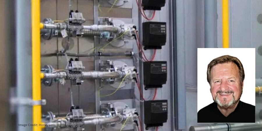
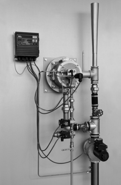
Figure 1. ECOMAX® with eductor and burner control unit BCU | Image Credit: Honeywell
There are some fairly sophisticated and exacting control systems that can use flow meters that compensate and monitor pressure fluctuations. The air and gas valving will then react to inputs from the orifice meters and pressure monitors. Some systems may even extract a sample of the flue gas at the exhaust, much like the sensors on your automobile catalytic converter. The use of these burner control units (BCUs) keeps burners tuned to exacting performance. A lab setup example of that technique is shown in Figure 1.
Other setups are quite simple and perform at their best on the normal setting. In other words, if the process temperature is 1850°F, engineers design burners to perform optimally at that temperature and for thermal input to be achieved 90% of the time. In this scenario, orifice plates and control valves set for that optimum performance hold the combustion system steady at that input; variations are minimal.
The burners may not run perfectly when coming up to heat, but that is hopefully a short-term situation, and as the furnace comes up to heat the burner, systems settle into a desired tune range. Think of these as the dragsters at a racetrack. We’ve all seen how they shudder and quake while waiting to go flat out down the racetrack. But when gas is pushed into them, they blow fire, smooth out, and go to unbelievable performance levels. Only we furnace guys would make that comparison… or maybe just this guy.
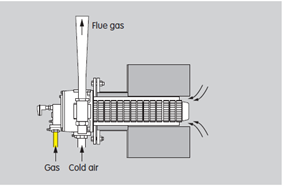
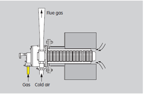
It bears noting that recirculation patterns can take on many variations depending on the type of heat treating you may be doing. Direct fired systems for stress relieving and straight up hardening operations use a high velocity direct fired system (Figure 2). That is where the aforementioned eductor pulls the flue gases out of the furnace and over the heat exchanger. Recirculation takes place in front of the burner in a high velocity stream exiting the nozzle. A percentage of the chamber gases gets pulled into that flue stream.
Figure 2. ECOMAX® in direct heating systems | Image Credit: HoneywellFigure 3. Examples of the design and the flue gas flow pattern | Image Credit: HoneywellFigure 4. Schematics of P-type and double P-types tubes | Image Credit: Honeywell
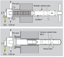
In the case of controlled atmosphere furnaces, where radiant tubes are utilized for the heating system, all sorts of different techniques exist. In the designs of recuperative recirculating style burners (i.e., FGR burners, flue gas recirculation), the tube designs are diverse and varied. Early designs of single ended tubes (SER) were the first to utilize recirculation designs (Figure 3).
Later, steel mills began to experiment and use P-type and double P-type tubes for strip annealing lines and galvanizing lines (Figure 4). You can see in these figures that the flue gases get pulled around, and we get the benefit of heat we have already generated and gas we have already burned. This creates a very good improvement in tube temperature uniformity and heat delivery. The arrows on the figures show the flow pattern of the gases.
So, in conclusion, there is no conclusion. Design improvements will continue to be made as long as we have requirements for efficient and emission-responsible operations in our heat treating plants and furnaces. Understanding that the world requires heat treating to be available for just about everything, and that we need to address those needs with ever-improving technologies… now THAT is pressure.
Till next time.
About The Author:
Jim Roberts President US Ignition
Jim Roberts president at U.S. Ignition, began his 45-year career in the burner and heat recovery industry focused on heat treating specifically in 1979. He worked for and helped start up WB Combustion in Hales Corners, Wisconsin. In 1985 he joined Eclipse Engineering in Rockford, IL, specializing in heat treating-related combustion equipment/burners. Inducted into the American Gas Association’s Hall of Flame for service in training gas company field managers, Jim is a former president of MTI and has contributed to countless seminars on fuel reduction and combustion-related practices.
In this installment of Answers in the Atmosphere, David (Dave) Wolff, an independent expert focusing on industrial atmospheres for heat treat applications, examines the market realities shaping argon supply and demand.
This informative piece on argon’s sourcing and distribution landscape, safety considerations, and emerging growth drivers — from U.S. titanium refining and powder metallurgy to the reshoring of domestic steel production —was first released in Heat Treat Today’sMarch 2026 Annual Aerospace Heat Treating print edition.
Akin Malas Business Development Manager / Metallurgist Linde
If you are just beginning to read this column, welcome. I encourage you to read the February 2026 installment to have a better understanding of the attributes of argon as an industrial gas for the thermal processing industry. Akin Malas, business development manager and metallurgist at Linde, joins me in this foray into argon, and we’re exploring market realities in this installment.
Though many companies compete for market share in the supply of gases such as nitrogen, oxygen, and hydrogen because they are relatively less expensive to source and process, the number of companies that have sufficient scale and expertise to produce and market argon is generally considered to be limited to the top tier of industrial gas companies like Linde, Air Liquide/Airgas, Air Products, Matheson, and Messer. Many other companies operate ASUs; however, very few of the plants are large enough to separate and purify argon. In the case of some ASUs owned and operated by very large steel mills, they generally sell their crude argon to industrial gas suppliers for purification and subsequent marketing and sales.
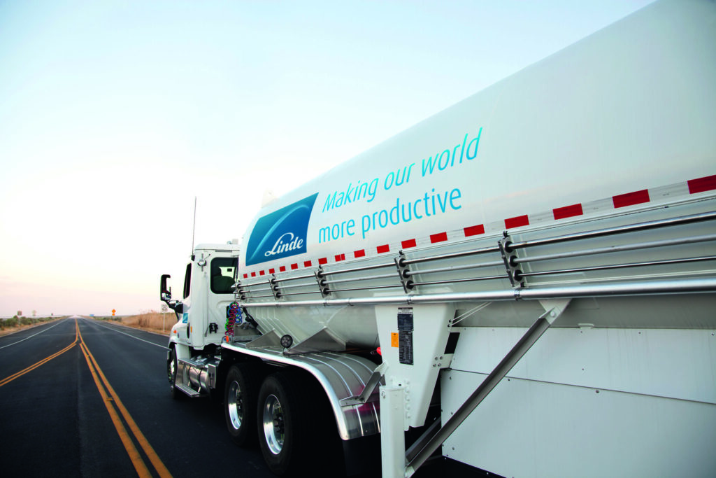
Linde gas delivery truck | Image Credit: Linde
Argon is delivered as a liquid cryogenic product (LAR), like liquid nitrogen (LIN), or liquid oxygen (LOX), but there may be differences in the storage and dispensing equipment installed at a client’s site due to the variety of uses for argon. Certain high-volume applications, such as ladle stirring and metals atomization, may require substantially higher pressure than normal cryogenic tanks are set up to store, making the use of boosters or cryogenic pumps necessary. If your application requires argon pressure to be above 100 psig, make sure that you are talking to a supplier that is experienced in providing and maintaining the equipment needed for your process.
From an NFPA codes standpoint, argon storage is comparable to nitrogen storage, and the clearances in NFPA 55 are the same for argon and nitrogen. But there are some key points to consider as far as safety in use:
While all cryogenic gases will create a vapor cloud that hugs the ground if there is a release, the clouds from nitrogen and oxygen will disperse and rise relatively rapidly as the gas warms. But because argon has much higher density than oxygen and nitrogen, a release will tend to hug the ground and can create a serious oxygen deficient atmosphere issue in low spots. Users of pit furnaces with argon need to be particularly aware of the unique characteristics of argon.
Because argon is generally shipped much longer distances than oxygen or nitrogen, tanks tend to be larger sized so that more can be delivered in a single visit. Since the transportation element of the price is considerable, keep in mind that your tank size (and NFPA clearance calculations) may be different than is typical for nitrogen.
While argon cannot be cost-effectively produced from air by non-cryogenic generation techniques (like membrane and PSA techniques used for nitrogen and oxygen), argon recovery/recycling is possible from argon-based industrial streams. A few of the larger industrial gas providers can provide recycling equipment that uses cryogenic separation technology to re-create very high purity argon from argon-rich offgas streams. Note that these installations are relatively expensive and specialized and are generally only of interest to the largest argon consumers.
After many years of relatively modest growth in the consumption of argon, several market segments are driving potentially important growth in argon use:
Several companies are developing U.S.-based titanium refining capabilities. Argon is required for processing and refining titanium metal, and the U.S. titanium production may become an important consumption driver.
Virtually all atomization of the special metals for powder metallurgical applications currently is done with argon used as the atomization gas. Though cheaper water-based atomization is being developed, it is not yet suitable for high quality powders. The metals powder industry has experienced strong growth and continues to grow.
The U.S. is reshoring iron and steel production, meaning that argon use for ladle stirring will rise. This means that overall argon use will rise, and that some new argon-capable ASU capacity will be built to serve the needs of new and refurbished steel plants.
Akin and I hope that these last two column installments have helped readers understand the factors in the market for argon that make it different in several ways from the more familiar nitrogen/oxygen marketplace.
About The Author:
David (Dave) Wolff Industrial Gas Professional Wolff Engineering
Dave Wolff has over 40 years of project engineering, industrial gas generation and application engineering, marketing, and sales experience. Dave holds a degree in engineering science from Dartmouth College. Currently, he consults in the areas of industrial gas and chemical new product development and commercial introduction, as well as market development and selling practices.
Ask The Heat Treat Doctor® has returned to bring sage advice to Heat Treat Today readers and to answer your questions about heat treating, brazing, sintering, and other types of thermal treatments as well as questions on metallurgy, equipment, and process-related issues. In this installment, Dan Herring continues his discussion on gear heat treatment, exploring vacuum and induction hardening methods for gears — from low-pressure carburizing for advanced materials to single shot and tooth-by-tooth induction techniques — and how each can be matched to the specific demands of any gear application.
This informative piece was first released in Heat Treat Today’sMarch 2026 Annual Aerospace Heat Treating print edition.
In Part One of this discussion (Air & Atmospheres Heat Treating, February 2026), we discussed various gear types, materials, and how they can be atmosphere heat treated. This month, we are focusing on vacuum and induction heat treating methods. Let’s learn more.
Vacuum Heat Treatment Processing Methods
Table A. Advanced Materials Processed by LPC
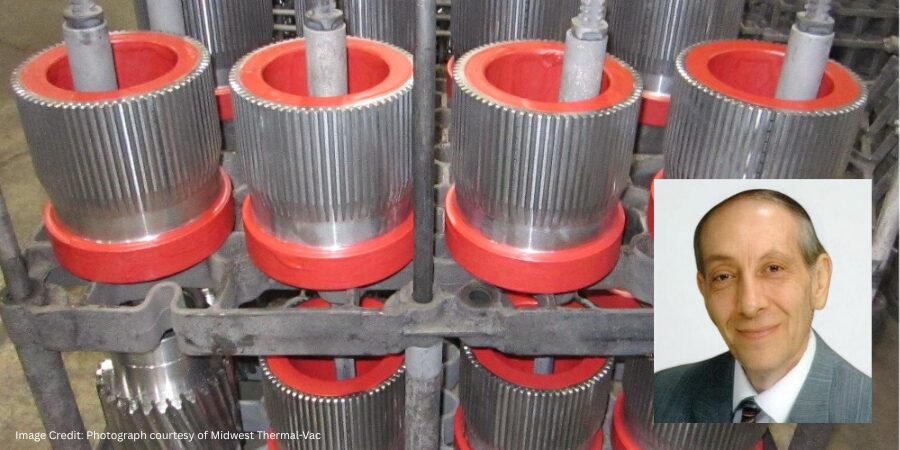
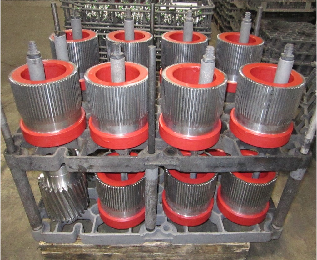
Vacuum processing can be used for most of the atmosphere treatments mentioned in Part One including carburizing (Figure 1). Low pressure carburizing (LPC) is a proven technology and the choice for many advanced applications in aerospace, automotive, off-highway, and motorsports markets, as well as the development of carburizing cycles for high-performance materials (Table A).
Figure 1. Typical commercial heat treat load of gears for vacuum carburizing (Otto and Herring 2007) | Image Credit: Photo courtesy of Midwest Thermal-VacFigure 2. Pyrowear 675 – LPC – anneal – double normalize – harden – anneal – deep freeze – double temper | Image Credit: The HERRING GROUP, Inc.
The range of effective case depths for most of these grades can range up to 2.0–3.0 mm (0.080–0.120 inches) without significant sacrifice of microstructure (Figure 2). Furnace variables, such as temperature uniformity (± 3°C or ± 5°F), control of cycle parameters (boost/diffuse times, gas flow rate, pressure, hydrocarbon type) and surface carbon optimize the microstructure, producing case uniformities of ± 0.05 mm (± 0.002 inches). Where permitted, the range of carburizing temperatures now includes the use of high temperature (> 980°C, or 1800°F) techniques.
All these advanced materials required extensive development testing to produce custom designed recipes to optimize cycle parameters. Also, quenching methods (Otto and Herring 2002) have improved, allowing us to achieve desired core properties with quenching parameter selection (high-pressure gas or oil) for distortion-sensitive and distortion-prone part geometries (Otto and Herring 2005, 2008).
Induction Hardening Methods
Various methods of hardening via applied energy are used in manufacturing gears, including flame hardening, laser surface hardening, and induction hardening.
Of the various types of applied energy processing, induction hardening is the most common. Induction heating is a process that uses alternating electrical current that induces a magnetic field, causing the surface of the gear teeth to heat. The area is then quenched resulting in an increase in hardness within the heated area. This process is typically accomplished in a relatively short time. The final desired gear performance characteristics are determined not only by the hardness profile and stresses but also by the steel composition and prior microstructure. External spur and helical gears, bevel and worm gears, racks, and sprockets are commonly induction hardened. Typical gear steels include AISI/SAE grades 1050, 1060, 1144, 4140, 4150, 4350, 5150, and 8650.
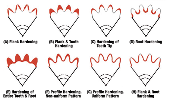
Figure 3. Patterns produced by induction hardening (Rudnev 2000)
The hardness pattern produced by induction heating (Figure 3) is a function of the type and shape of inductor used, as well as the heating method. Quenching or rapidly cooling the workpiece can be accomplished by spray or submerged quench. The media typically used for the quench is a water-based polymer. The severity of this quenchant can be controlled by the polymer’s concentration. Cooling rates are usually somewhere in between what would be obtained from pure water and oil. In some unusual situations compressed air or nitrogen is used to quench the part.
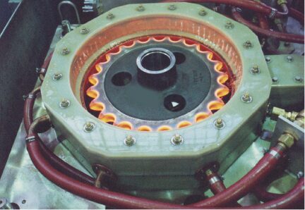
The most common methods for hardening gears and sprockets are by single shot (Figure 4) or the tooth-by-tooth method (Figure 5). Single shot often requires large kW power supplies but results in short heat/quench times and higher production rates. This technique uses a circumferential copper inductor, which will harden the teeth from the tips downward.
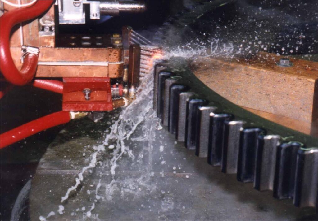
Figure 4. Typical single shot induction hardening operation | Image Credit: Photo courtesy of Ajax-Tocco-MagnethermicFigure 5. Tooth-by-tooth induction hardening of a helical gear | Image Credit: Photo courtesy of Ajax-Tocco-Magnethermic
The larger and heavier loaded gears (where pitting, spalling, tooth fatigue, and endurance are issues) need a hardness pattern that is more profiled like those produced by carburizing, which can be obtained by tooth-by-tooth hardening. This method is limited to gear tooth sizes with modulus 4.23–5.08 (6 or 5 DP) using frequencies from 2 to 10 kHz and about 2.54 (10 DP) using a range of 25 to 50 kHz.
The lower the frequency, the deeper the case depth. Tooth-by-tooth hardening is a slow process and usually reserved for gears and sprockets that are too large to single shot due to power constraints. The process involves heating the root area and side flanks simultaneously, while cooling each side of the adjacent tooth to prevent temper-back on the backside of each tooth. The induction system moves the coil at a pre-programmed rate along the length of the gear. The coil progressively heats the entire length of the gear segment while a quench follower immediately cools the previously heated area. The distance from the coil to the tooth is known as coupling or air gap. Any changes in this distance can yield variation in case depth, hardness, and tooth distortion. The gear is indexed after each tooth has been hardened, often skipping a tooth. This requires at least two full revolutions in the process to complete the hardening of all teeth. Straight, spur, and helical gears up to 5.5 m (210 inches) weighing 6,800 kg (15,000 lb) have been processed with this method. The entire process yields a repeatable soft tip of the tooth with hard root and flank. In other applications, the tip and both flanks can be hardened simultaneously and yield a soft root.
In Summary
Today’s design engineer has the good fortune of being able to choose from a number of heat treatment technologies for any given type of gear material and design. When selecting a gear hardening method, it is essential to specify not only the desired mechanical and metallurgical properties, but the critical dimensions that must be held and even the desired stress state of the gears themselves. The secret to success is understanding the advantages and limitations of each technology and taking these into consideration when determining the overall cost of gear manufacturing.
References
Herring, Daniel H. 2004a. “Gear Heat Treatment: The Influence of Materials and Geometry.” Gear Technology, March/April.
Herring, Daniel H. 2004b. “Reducing Distortion in Heat-Treated Gears.” Gear Solutions, June.
Herring, Daniel H. 2007a. “Oil Quenching Technologies for Gears.” With Steven D. Balme. Gear Solutions, July.
Herring, Daniel H. 2007b. “Heat Treating Heavy Duty Gears.” With Gerald D. Lindell. Gear Solutions, October.
Herring, Daniel H. 2012–2016. Vacuum Heat Treatment. Vols. 1–2. BNP Media Group.
Herring, Daniel H. 2014–2015. Atmosphere Heat Treatment. Vols. 1–2. BNP Media Group.
Herring, Daniel H., Gerald D. Lindell, D. J. Breuer, and B. Matlock. 2001. “Atmosphere vs. Vacuum Carburizing.” Heat Treating Progress, November.
Herring, Daniel H., Gerald D. Lindell, D. J. Breuer, and B. Matlock. 2002. “An Evaluation of Atmosphere and Vacuum Carburizing Methods for the Heat Treatment of Gears.” In Off-Highway Conference Proceedings. SAE International.
Otto, Frederick J., and Daniel H. Herring. 2002a. “Gear Heat Treatment: Today and Tomorrow, Part 1.” Heat Treating Progress, June.
Otto, Frederick J., and Daniel H. Herring. 2002b. “Gear Heat Treatment: Today and Tomorrow, Part 2.” Heat Treating Progress, July/August.
Otto, Frederick J., and Daniel H. Herring. 2005. “Vacuum Carburizing of Aerospace and Automotive Materials.” Heat Treating Progress, January/February.
Otto, Frederick J., and Daniel H. Herring. 2007. “Advancements in Precision Carburizing of Aerospace and Motorsports Materials.” Heat Treating Progress, May/June.
Otto, Frederick J., and Daniel H. Herring. 2008. “Improvements in Dimensional Control of Heat Treated Gears.” Gear Solutions, June.
Rudnev, V. 2000. “Gear Heat Treating by Induction.” Gear Technology, March/April.
About the Author
Dan Herring “The Heat Treat Doctor” The HERRING GROUP, Inc.
Dan Herring has been in the industry for over 50 years and has gained vast experience in fields that include materials science, engineering, metallurgy, new product research, and many other areas. He is the author of six books and over 700 technical articles.
Jim Roberts of U.S. Ignition engages readers in a Combustion Corner editorial about the hidden complexity of balancing furnace pressures —explaining how thermal expansion, gas velocity, and pressure fluctuation interact in modern burner systems, and how flue gas recirculation can push firing efficiency from 30% to 75% while cutting NOx emissions by more than half.
This editorial was first released in Heat Treat Today’sMarch 2026 Annual Aerospace Heat Treating print edition.
When I made the comment about the negative attitude in Part 1 of this series (Air & Atmosphere Heat Treating, February 2026), I was referring to the fact that most of these burner designs require a suction component (in this case, the eductor) to help pull the exhaust gases out over the heat exchanger portion of the burner. Also, if we just tried to pressurize the burners and force the exhaust gases out through the exchanger section, there would be a pressure buildup in the furnace. With that comes the destruction of door seals. Burner plates begin to leak, and when the doors open, the operators and furnace guys get greeted with a blast of 2000°F flue gas. I can honestly say, I have not, in all my years in this industry, met a furnace guy who likes a thermal haircut.
So, by balancing the pressures, we can save gas, reduce emissions, and probably even heat treat some products along the way.
A comment like, “just balancing the pressures,” seems like such an easy thing to accomplish. And, for all the experienced furnace guys out there, that is probably regarded as pretty simple stuff. But we have to give proper respect to the myriad of moving parts in today’s modern burners and heating systems. When I say moving parts, perhaps the better description is designing around the fluctuations in pressures, temperatures, and flows that these modern systems all perform to operate at these efficiencies.
When Combustion Corner covered pressures and velocities in August and September 2025, you will recall that under these temperatures, everything starts moving around under the temperature growth and pressure increases. Velocity increases like crazy, and at heat treating temperatures, the very components expand significantly enough to affect the pressure and delivery of flue gases.
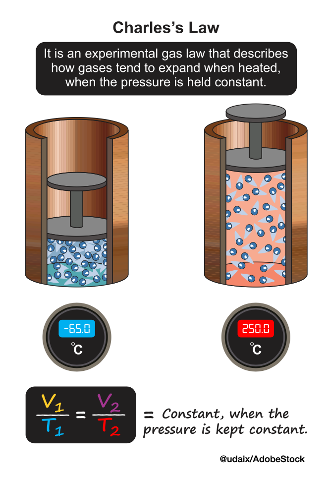
High temperatures cause flue gases to expand significantly because increased thermal energy boosts gas molecules’ kinetic energy, making them move faster and spread out. This principle, described by gas laws like Charles’s Law, leads to volume increases that necessitate expansion joints in equipment to prevent system damage and maintain integrity. This expansion can create immense stress on combustion systems, requiring specialized components like expansion joints to absorb thermal growth and maintain seals, while the high heat can also induce chemical changes and dissociation, influencing performance in other ways.
For example, can you begin to envision how furnace designers and burner design engineers have to pay attention to component growth while maintaining the critical pressures of the furnace and the burners and heat exchangers? It’s a dance, let me tell you! I believe I pointed out a while back that a 6-inch diameter radiant tube or burner combustor will grow almost an inch in length when running at 1400°F and above. If it’s growing in length, it is also trying to grow in diameter. It’s like trying to produce a constant flow of water at a constant spray rate on your garden hose, all the while the hose is changing dimensions. Not so easy is it?
To sum up, with heat recovery, and then with the addition of flue gas recirculation and high velocity burners, it is really quite remarkable how well many of these systems perform. The firing efficiency of a flue gas recirculation system over a conventional cold air burner can be the difference of 30% fuel efficiency and 75% fuel efficiency! We are talking about some serious fuel dollar savings when that all happens. And now, with recirculation, you are also cutting NOx by better than half as well.
Next time we will talk about how these systems do all of this.
About The Author:
Jim Roberts President US Ignition
Jim Roberts president at U.S. Ignition, began his 45-year career in the burner and heat recovery industry focused on heat treating specifically in 1979. He worked for and helped start up WB Combustion in Hales Corners, Wisconsin. In 1985 he joined Eclipse Engineering in Rockford, IL, specializing in heat treating-related combustion equipment/burners. Inducted into the American Gas Association’s Hall of Flame for service in training gas company field managers, Jim is a former president of MTI and has contributed to countless seminars on fuel reduction and combustion-related practices.
In this installment of Answers in the Atmosphere, David (Dave) Wolff, an independent expert focusing on industrial atmospheres for heat treat applications, explores the practical role of argon as a truly inert alternative to nitrogen in thermal processing.
This informative piece on argon’s unique properties, production challenges, and applications — from vacuum heat treating of titanium to powder metallurgy and additive manufacturing —was first released in Heat Treat Today’sFebruary 2026 Annual Air & Atmosphere Heat Treating print edition.
Akin Malas Business Development Manager / Metallurgist Linde
In this column, I’ve invited Akin Malas, business development manager and metallurgist at Linde, to bring his deep expertise in the subject of argon gas. What follows is the fruit of our discussion and continued conversations about this specialized yet indispensable industrial gas in thermal processing applications.
Compared to nitrogen (the industrial gas this column last covered), argon exhibits actual inertness, enabling its use in high-temperature environments and for processing metals that cannot tolerate nitrogen atmospheres, such as titanium and certain high-performance stainless steels. While argon is significantly higher cost than nitrogen, it remains far more economical than helium, another highly inert alternative.
Argon plays a vital role across multiple stages of metal processing, including:
Primary metallurgy: ladle stirring
Powder metallurgy: atomization of metal powders
Additive manufacturing: laser and electron-beam processes requiring inert chamber atmospheres
Vacuum heat treating: backfill gas for titanium and specialty alloys
Argon is used differently than nitrogen in most cases. Inexpensive nitrogen is often used as a utility pressurization gas, for scavenging, and blended with other gases (such as hydrogen); however, argon is most often used in pure form. Nitrogen is considered inert for heat treatment applications except in extraordinarily high temperatures or heat treatment of reactive metals, such as titanium and stainless steels. In this case, using an actual inert gas like argon or helium is necessary. Also, while nitrogen is virtually the same density as air and thus will diffuse throughout a vessel, argon is much denser than air and can be used to form a stratified inert layer.
Linde gas storage tanks | Image Credit: Linde
Both argon and nitrogen are separated from air in a cryogenic air separation unit (ASU), but there are three main factors that make argon much harder to make than nitrogen and thus much more expensive:
Argon is only 1% of air while nitrogen is 78% of air. Argon boils at nearly the same temperature as oxygen, making a separate purification process necessary. Those two factors mean that only the largest ASUs make enough argon to make it worth purifying.
Argon cannot economically be separated from air non-cryogenically (primarily because the percentage in air is so low), so there is no low-cost competition to cryogenic argon. Also, because argon is prized for its inertness, there is much less interest in argon that might be lower purity.
Because argon is made in only the largest ASUs (typically those serving very large steel mills) and because those plants tend to be geographically grouped, shipping distances for argon tend to be much farther than for nitrogen and oxygen, further driving up the costs.
Processors of titanium parts and parts made of some stainless steels, such as the 300 series stainless alloys (SS), cannot be processed in nitrogen-containing atmospheres, because the metals will nitride at heat treating temperatures. Hence these metals may be processed in a pure argon (for Ti) or hydrogen (for SS) atmosphere blends.
We’ll pick up this discussion next month to see what market options are available, particularly in the U.S.
About The Author:
David (Dave) Wolff Industrial Gas Professional Wolff Engineering
Dave Wolff has over 40 years of project engineering, industrial gas generation and application engineering, marketing, and sales experience. Dave holds a degree in engineering science from Dartmouth College. Currently, he consults in the areas of industrial gas and chemical new product development and commercial introduction, as well as market development and selling practices.