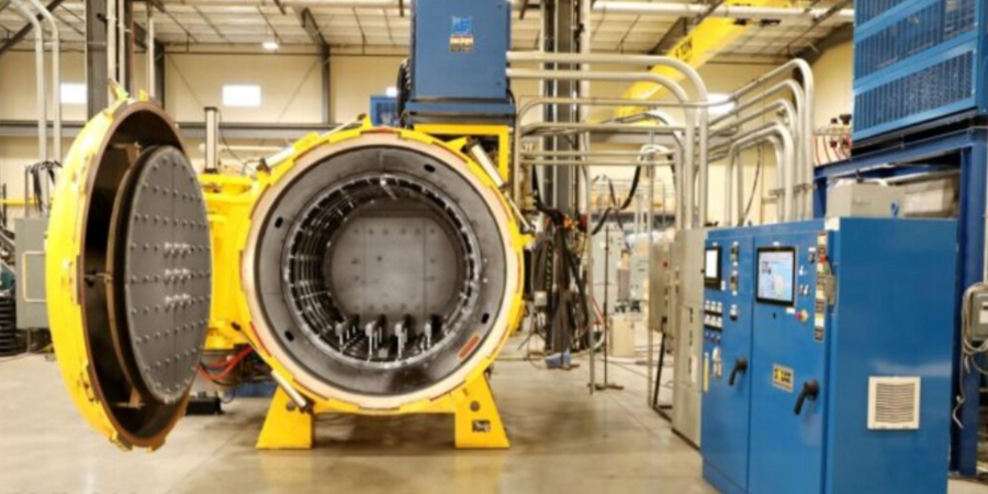
Recently, Solar Atmospheres Eastern PA commissioned a new 25,000 square foot brazing facility aimed at high-volume, high-quality braze production. The facility features six vacuum furnaces dedicated to brazing, including an all-metal hot-zone furnace designed for brazing stainless steel to copper with silver and gold-based braze filler metal (BFM).
The heat treater specializes in the brazing of high-value components utilizing filler metals based on nickel, silver, gold, and copper. The new state-of-the-art production facility has 4,000 square feet of climate-controlled workspace, where technicians assemble and inspect parts, ranging from tiny capillary-tube manifolds to large land-based gas turbine blades. The operation incorporates increased capacity for helium leak testing and pre-braze tack welding of braze assemblies.
“With Nadcap accreditation and AS9100 registration, our new facility operates as one expects from the Solar brand,” states Chip Lahneman, general manager of Brazing at Solar. “The investment in our new facility demonstrates Solar’s commitment to meeting our customers brazing needs, now, and in the future.”
Find heat treating products and services when you search on Heat Treat Buyers Guide.com
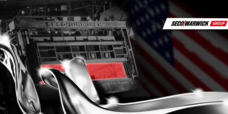
A multinational aluminum producer ordered a new 100,000 lb. capacity tilt melting aluminum furnace for one of their regional aluminum extrusion plants. Fabricated in PA, the furnace will incorporate several features to meet the manufacturer’s efficiency, production, and capacity requirements, as well as options to accelerate melting and transfer flow.
SECO/WARWICK USA will fabricate this aluminum reverb furnace. “Most of the damage to a furnace like this is from loading it with a forklift,” comments Marcus Lord, managing director at SECO/WARWICK USA. “Either bumping into the refractory around the door or being a bit clumsy with large awkward chunks of aluminum. It means the door is open a lot, and when it is closed, it might not have the best seal because the sills, jams and lentils are all beaten up. This furnace has a separate loading mechanism, so the door doesn’t need to open nearly as often. It really extends the life of the refractory, but it’s a huge efficiency boost too.”
This furnace will be fabricated with additional features, including capabilities to allow for a magnetic stirrer (supplied by the client) to be mounted under the furnace, saving more energy by increasing the melt rate by up to 10%. It will be capable of completely one full batch cycle in under 6 hours, for four batches a day, yielding a total of 340,000 to 400,000 lbs. per day. These combined factors will result in a fuel economy when the burners are firing in the regenerative mode of less than 1200 BTU per pound during the melt cycle.
Find heat treating products and services when you search on Heat Treat Buyers Guide.com
In the past, manufacturers with in-house heat treat have turned to hot isostatic pressing (HIP) technology to decrease porosity and increase densification in their processed parts. Now, in 2023, is there anything new HIP can offer heat treaters? To find out, Heat TreatToday asked seven HIP equipment suppliers and heat treat users to enlighten us on the world of HIP as it is today.
Enjoy this original content contribution, first released in Heat TreatToday'sMarch 2023 Aerospaceprint edition!
What are the recent, cutting-edge developments in HIP?
Matt Fitzpatrick
Sales Engineer
Engineered Pressure Systems, Inc.
Source: EPSI
Matt Fitzpatrick, sales engineer at Engineered Pressure Systems, Inc., shares, “Self-diagnosing alarms, failures, and power as well as medium consumption savings are key developments in the HIP industry. Enhanced uniform cooling joins with the development of materials (ceramics, metals, insulation fibers) to improve equipment uptime and reduce cycle time. Self-diagnosing alarms may play a key role in HIP’s future. Each HIP control system has alarms to alert when parameters are not met. The future will be in determining why the parameters are not being achieved. For instance, future control systems may be able to diagnose a bad thermocouple, a failed motor solenoid valve, a leaking high pressure valve, etc.
Contact us with your Reader Feedback!
“Unfortunately, there are not very many HIP systems purchased every year. It takes time to develop this technology. A good example would be the automotive industry: sensors tell technicians exactly where the problem in the vehicle is. As the PLCs and computers become more advanced, the specific software programs that are developed for the HIP system — in conjunction with advancements with sensors in motors, pumps, valves, transducers, meters, and components — will make it easier and less time consuming to develop complex troubleshooting programs.
“To some heat treaters, HIP can be an unnecessary evil, given its expensive, long cycle times. HIP, however, cannot be eliminated, because it is the only process that attains the densification required in the aerospace, medical, and high-performance automotive industries.”
Cliff Orcutt
Vice President
American Isostatic Presses, Inc.
Source: American Isostatic Presses, Inc.
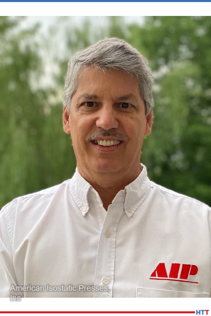
“HIP technology is very mature and reliable,” Cliff Orcutt, VP of American Isostatic Presses, Inc. assures, “however, the cost to use the process is always one major hurdle preventing its use. AIP is working hard to develop lower cost equipment that can still maintain excellent results and bring higher pressure capabilities to the market. We are also expanding our footprint further into the toll HIP arena with similar goals of lower cost and faster turnaround services. Our new facility opening in Columbus, OH, this spring will also provide a world class development resource to help interested manufacturers determine whether the process can be applied to their parts.”
Chad Beamer
Applications Engineer
Quintus Technologies
Quintus Technologies’ Chad Beamer points to the versatility of HIP: “HIP continues to make its mark in many industries by offering a path to consolidate powders and eliminate process related defects for 100% pore and void free material for improved product integrity. With the continued demand for this special process, Quintus Technologies has several key developments driving industry growth due to the expanding functionality of the equipment. The voice of the client consistently demands production efficiency, reduced environmental impact, and improved process reliability. Modern HIP equipment is delivering on this front, creating a promising future for HIP.
“HIP systems equipped with rapid cooling and quenching functionality (URC®/URQ®) are facilitating lean manufacturing with increased productivity by shortening the cooling segment over conventional cooling, while also offering the opportunity to consolidate thermal post processing steps. HIP systems with URC® can cool at rates up to 932°F/min (500°C/min), and compact HIP units with URQ® furnaces are capable of cooling more than 5400°F/min (3,000°C/min). This leads to the opportunity to combine several thermal processing steps into one process performed under pressure. The combined, or integrated, heat treatment approach inside the HIP vessel is known as High Pressure Heat Treatment™ (HPHT™).
“Developments with the controllability of HIP are further expanding the use of HPHT. The cooling rate of the HIP can be steered using thermocouples to set the desired cooling rate from either process gas or component temperature feedback. Steered cooling driven by the component temperature is interesting when considering different thicknesses of parts in the HIP. The machine can therefore autonomously steer the temperature based on the thickest component to achieve desired material properties. See an example of steered cooling from component temperature feedback in the graph above.
“The tailoring of HIP cycles is a new area of development too. Due to the excellent controllability in a modern HIP tailored heating, sustaining, and cooling segments can be programmed and precisely executed. This is an area of interest for materials needing high cooling rates or having a tight tolerance on heating and cooling rate requirements. An excellent example of a tailored HIP cycle can be seen in recent work by Goel et al., at the University West in Sweden (see illustrations above), capturing the possibility to significantly reduce the treatment time for additively manufactured Inconel 718.
“Quintus has also been working to reduce discoloration and oxides on the surface of parts by improving equipment and best practice in terms of clean HIP operations. This is not an easy challenge to overcome. HIP is performed at very high pressures, often above 1000 atmospheres, using high purity Argon gas (>99.99x). Because of the need for additional gas volumes to achieve desired system pressure during regular HIP, the total pressure of contaminants can become high. Despite these challenges it is now possible to produce materials that have a high affinity for oxygen e.g., aluminum, titanium, and chromium, with significantly less oxidation. This can lead to improvement in fatigue and corrosion resistance fulfilling design criteria and gives great opportunities for more sustainable post-HIP.
“Developments with the digitalization of HIP equipment are also playing a role in meeting the demand of the Industry 4.0 mindset. Integration of the equipment into digitalized production lines enables product and process improvements. Digitalization of high-pressure equipment offers many benefits as it creates opportunities to streamline and save time with preventative maintenance tasks, provides valuable insights and trends into the health of the equipment, expands collaboration, improves uptime, and saves cost.”
Humberto Ramos Fernández
Founder and CEO
HT-MX
“In 2023,” Humberto Ramos Fernández, founder and CEO of HT-MX, comments, “HT-MX will continue to establish itself as the main HIP supplier and expert in Latin America. Additionally, with our Honeywell Aerospace approval, we will be pursuing at least three more OEM approvals not only in the aerospace industry but medical and automotive as well.”
Phil Harris
Marketing Manager
Paulo
Phil Harris, marketing manager at Paulo, highlights HIP’s customization: “The primary focus has been on providing customized HIP cycles that either deliver superior mechanical properties for customers or reduce the need for post-HIP to streamline the supply chain and speed up turnaround. We’ve been successful in both and are always looking for opportunities to collaborate on such endeavors.”
Leah Tankersley, marketing manager, Aalberts surface technologies, says, “We added HIP services to our portfolio in 2020. We have two wire-wound HIP vessels, and plan to expand further with a third unit ready to ship from Sweden soon. Each unit boasts the latest HPHT technology. They are equipped with the proprietary Uniform Rapid Cooling (URC) feature. Our HIP technology has the ability to combine stress relief, HIP, solution, and age in a single process. HPHT HIP streamlines the steps involved in material densification and heat treatment. The URC feature enables all processed components to cool uniformly in a controlled environment, resulting in minimal thermal distortion and non-uniform grain growth.”
Doug Puerta
CEO
Stack Metallurgical Group
Source: Stack Metallurgical Group
Doug Puerta responds for Stack Metallurgical Group: “Stack has been active in supporting the advancement of HPHT. Our newest HIP unit, a Quintus QIH-122, includes Uniform Rapid Cooling (URC) technology which enables cooling rates equivalent to what we achieve with traditional gas quenching. This technology not only allows for improved productivity, but also enables the combination of a traditional HIP cycle with stress relieving solution annealing, or even aging, all in one HIP unit.”
In the next five years, what advancements should manufacturers with in-house heat treat operations expect from HIP technology?
“In terms of cycle times,” Matt Fitzpatrick of Engineered Pressure Systems, Inc. says, “HIP systems are limited by how fast materials can be heated and cooled. In the next five years, reduced maintenance, improvements with furnaces and heat shields, and faster cycle times will occur at both the materials and design levels.”
Cliff Orcutt, from American Isostatic Presses, Inc., sees globalization in HIP’s future, “We don’t expect much change other than to see it expanding into new geographic regions and being applied to more products. The main problem affecting our industry is not deficiencies in the HIP equipment or process, but rather how to use it beneficially in a profitable manner. In the next five years I think countries, such as India, will begin to implement it much more widely as the process becomes better known. As more companies implement it their competition must follow to stay on the same page.”
Chad Beamer, from Quintus Technologies, shares the optimistic outlook, “Quintus is witnessing significant growth potential for HPHT, including the addition of this post-process HIP and heat treatment strategy into industry standards. Also, the demand placed by many industries on surface cleanliness requirements to reduce oxidation and discoloration of sensitive material systems will help drive forward clean HIP techniques. These advancements along with delivering new and upgrading existing HIP equipment with machine digitalization will meet the current and future demands placed by the heat treat market and OEMs.”
And what about HIP in Mexico? Humberto Ramos Fernández of HT-MX responds, “Being located in Mexico, the main advances in HIP in our environment will be mostly geared towards near shoring manufacturing for high added value parts. HT-MX´s HIP service is just one example of a high tech and high complexity process being used in Chihuahua to manufacture high end products and thus we expect near shoring to bring in more opportunities for these kinds of parts to be manufactured and assembled in Chihuahua and Mexico.”
Leah Tankersley of Aalberts surface technologies, says, “As a provider of HIP services, we cannot speak to the advancements in HIP technology per se, but we are seeing material advancements and development of new alloys in AM. These advancements will impact HIP cycles and lead to development of more unique cycles for AM that differ from traditional cycles developed for castings. We’re also seeing ASTM International AM Center of Excellence Consortium members from the AM value stream come together to collaborate on standardization of requirements for AM materials data which includes post processing/hot isostatic pressing. We are one of the founding members of this consortium.
“Additionally, we are working with Quintus to beta test their remote assistance fi eld service support through AR equipment and technology.”
Doug Puerta, Stack Metallurgical Group, thinks, “In the next five years, I expect we’ll continue to see aerospace and medical OEMs evaluate and approve HPHT for additional combined-cycle applications. Ultimately, with span time being so important to our customers (and their customers), combining cycles and reducing span is a really big deal.”
What is the #1 thing manufacturers with in-house heat treaters should know about HIP technology right now?
Safety first, says Matt Fitzpatrick at Engineered Pressure Systems, Inc. (EPSI): “Good safety and maintenance programs and experienced operators and technicians are key to a successful HIP system. Confined space rules and regulations, oxygen monitoring, nondestructive testing (NDT) inspections of the vessel assembly components, good maintenance, and end-user HIP plant safety programs are key. Training is provided with every system regardless of whether it’s a HIP system, CIP system, or WIP system. Before delivering a system, EPSI offers training for safety, maintenance, system operation, controls, and system parameters. Then during installation and startup, training occurs. When startup is completed, we offer training at the client’s site. Generally, this is mutually agreed on during the contract phase and delivery.”
“There is not just one thing,” Cliff Orcutt of American Isostatic Presses, Inc. says, “because HIP has so many different applications. For instance, HIP can be used to heal castings, make parts directly from powders, diffusion bond materials together, or pressure infiltrate materials. HIP can be applied to metals, ceramics, composites, and even plastics. I guess really the number one thing they should know is how to contact a reputable HIP company that can provide the information and technology they require.”
Chad Beamer of Quintus Technologies points to HIP’s benefits for both end customers and heat treaters, “Modern HIP units differ significantly from conventional HIP units. The technology has advanced over the decades offering expanded functionality and improved performance. As for all production processes, lean manufacturing is key to improving product quality, minimizing costs, and maximizing productivity. Reducing waste and increasing throughput should always be a focus.
“The addition of modern HIP with HPHT capability and clean HIP functionality as part of the production chain are HIP advancements that will facilitate robust and lean processes through reduction of yield losses, logistics, and quality-related costs. This is not only of strong interest to heat treaters, but also to the end customers in several industries. And with a broad product line of compact, medium, and large HIP capabilities available, commercially in-sourcing the technology to complement other heat treat equipment is now feasible for many companies.”
Humberto Ramos Fernández speaks directly to in-house heat treaters, “In-house heat treaters must know that, although similar, HIP is not heat treatment. Various aspects of the process are similar but there is a learning curve that must be transitioned and experience in heat treat doesn’t necessarily automatically translate into the HIP experience.”
Aalberts’ Leah Tankersley plainly states, “HIP is an expensive investment.”
“Ironically,” says Doug Puerta of Stack Metallurgical Group, “One of the misconceptions is that modern HIP systems offer HPHT as an alternative to general heat treating. The intent of technology is for use when conventional HIP and heat treatment is required for a given application. When HIP is not required, heat treating is performed in a traditional vacuum furnace. The economics don’t really support heat treating in a HIP unit when a HIP segment is not included.”
How is HIP benefiting heat treaters in the industry today?
Matt Fitzpatrick, from Engineered Pressure Systems, Inc., says, “First, we employ heating and cooling software program models to help with cycle times, though cycle time generally depends on the material being processed.”
Fitzpatrick continues, “Loading and unloading a HIP cycle can be time consuming. We have developed tooling that helps operators prepare a HIP cycle and test the thermocouples prior to being loaded into the HIP vessel. In addition to reducing time, this tooling ensures that the load is prepared properly and won’t damage the furnace while it goes into the vessel.”
Cliff Orcutt, American Isostatic Presses, Inc., replies, “We have many clients that use our HIP systems to improve the properties of AM parts, as sintering alone has a limited upper range for density achievement. By utilizing HIP they are able to achieve near theoretical density and remove voids that can degrade performance or affect surface post finishing. In many cases when you have improvement in properties it can allow redesign with less material usage to improve cost efficiency and help the environment.”
Chad Beamer of Quintus Technologies explains, “HIP is a well-established process that has played a role in delivering advanced materials and components since the 1960s. Originally developed as a diffusion bonding process, its use has expanded to the densification of castings and additively manufactured components as well as the consolidation of powder to produce billets of material or complex near net shapes. Several industries benefit from its use today including aerospace, space, power generation, medical, oil and gas, and nuclear to name a few.
“The process offers several benefits related to material performance. One of the main demands for HIP is to eliminate process-related defects in materials for improvement in mechanical properties. Dynamic properties such as fatigue and creep performance are significantly improved, as is ductility and fracture toughness. The elimination of internal defects leads to reduced mechanical property scatter offering more predictive properties. The outcome can offer extension of a component’s lifecycle as well as potential weight-savings and cost reduction. Another benefit of HIP is for the enhancement of surface quality. The absence of internal defects provides a path to produce machined and polished surfaces free of surface connected imperfections for improvement in mechanical properties and corrosion resistance, as well as optical properties for aesthetically critical applications.
“For heat treat service providers there is motivation to invest in HIP capabilities as it provides a natural complement to existing heat treatment equipment often offering a one-stop shop at many facilities. It also broadens the availability and flexibility of HIP and HPHT services to the industry which is an exciting opportunity.
“As for an OEM’s decision to insource HIP, the benefits are broad. The capabilities of modern systems lead to significant reduction in the production cycle time, savings in overall handling and cost, especially with custom HIP cycles. It also provides a path to gain more control of processing techniques with the opportunity to develop novel approaches while improving control of the intellectual property that is developed.”
Humberto Ramos Fernández, HT-MX responds, “For high value parts, such as aerospace engine components, lead times mean money. Being able to reduce, by weeks, the turnaround time for HIP parts in Mexico means that working capital for these parts is significantly reduced allowing our customers to enjoy these savings.”
Paulo’s Phil Harris says, “HIP, in conjunction with customized cycles, is allowing our customers to deliver parts which were previously not possible. Specifically, the ability to meet material property requirements with additive parts. Where traditional HIP cycles (designed for castings) left them short of tensile requirements, we’ve been able to achieve the necessary properties, winning both of us more work in the process. This success in turn drives the adoption of additive manufacturing.”
Leah Tankersley, Aalberts surface technologies adds, “Our customers benefit from the latest HPHT HIP technology to improve the materials characteristics of their parts. HPHT HIP helps clients reach 100% theoretical density after HIP, improve
tensile strength, and improve creep rupture properties.
“Our URC technology allows clients to reduce lead times with the ability to combine stress relief, HIP, solution, and age into one cycle which saves time by reducing the number of individual process steps and handling of parts. If clients choose to not do stress relief in the HIP, stress relief can be done in the vacuum furnaces that are just 50 feet away from the HIP system in our facility.”
Stack Metallurgical Group’s Doug Puerta replies, “We’ve had the good fortune to introduce several of our clients to the benefits of HIP. While HIP has long been mandated in quality critical industries such as aerospace, orthopedic implant, and power generation, there are other applications where significant performance gains can be achieved through HIP.”
For more information, contact the experts:
Matt Fitzpatrick
Sales Engineer, Engineered Pressure Systems, Inc.
mattfi tzpatrick@epsi-highpressure.com
Cliff Orcutt
Vice President, American Isostatic Presses, Inc.
corcutt@aiphip.com
Chad Beamer
Applications Engineer, Quintus Technologies
chad.beamer@quintusteam.com
A vacuum furnace was recently shipped to a firearms manufacturer based in the Midwest United States. The heat treat furnace will primarily be used to anneal firearm components.
Solar Manufacturing, based in Sellersville, PA, shipped a Model HFL-5748-2IQ furnace that has a graphite insulated hot zone of 36” x 36” x 48” with a weight capacity of 5,000 lbs., and maximum operating temperature of 2400°F.
“This was the first vacuum furnace our customer had purchased for their in-house heat treating,” commented Adam Jones, sales manager for the Midwest region at Solar Manufacturing. The company assisted with the furnace installation.
Find heat treating products and services when you search on Heat Treat Buyers Guide.com
Since 2018,Heat Treat Today has been striving to honor young people in the industry. The 40 Under 40 award gives names, faces, and words to the rising generation of industry professionals.
Catch up with exemplary classmates from the past year to hear where they are now and what comments they have about the industry. Pour a cup of coffee while you dig into the resource list that’s full of research and commentary from Heat TreatToday‘s40 Under 40 alumni.
This original content article is released on the final day to nominate someone to Heat TreatToday‘s 40 Under 40 Class of 2023.
Aniket Maske
Aniket provided an update: “Currently, I’m the Chief Metallurgist and Director of Quality and Launch (program management) at ASPC. In addition, I’m now part of the Executive Leadership Team (ELT).”
At Automatic Spring Products Corp., heat treating processes have significantly improved with Aniket as a member of the Senior Leadership Team. Long-term strategic planning, reducing customer complaints, improving customer relationships, and implementing corrective actions to improve processes are all areas that see his influence. He has been an integral part in helping ASPC transition to the latest technology in heat treat controls and fuel injection which will result in significant gas savings and increased quality and control.
This recognition inHeat TreatToday‘s 40 Under 40, Aniket explains, “[has] helped me in networking as I focus on future sustainability – which is important as a heat treat professional. The professionals in the heat treat industry are provided a platform to collaborate and know about the progress – which was not readily available on a mass scale – with larger scope and scale.”
This Class of 2022 alum closes with the fact that he “enjoy[s] reading Doug’s editorial page in Heat Treat Today magazine.”
With a bachelor’s degree in Materials Science and Engineering from Penn State, Sarah worked as a metallurgist, and has been gaining experience in aerospace industry quality systems in the heat treat industry for 18 years, beginning with an internship at Sikorsky Aircraft.
“Things continuously improve,” she explained. “Even though we’ve been heat treating steel for decades, there’s always something new coming out: new material, new processing methodology, etc.”
Sarah has this advice for future leaders in the industry: “Get involved. Join and organization such as MTI; explore the NADCAP program; look into AMEC and writing standards we use everyday. Get involved, and do the networking. It will take you farther than you can imagine.”
During this past year, Casey has completed his MBA from University of Michigan in April. He shares gratitude for those who helped him along the way: “First and foremost I could not have done it without the unwavering support of my wife Anna O’Neill, MBA. I also sincerely appreciate Bob Roth’s encouragement to pursue this degree. It was both a challenging and rewarding experience. Thank you Nelson Sanchez, Kurt Hofman and everyone at RoMan Manufacturing for your guidance, support and and patience as I did my best to juggle all the work we are doing at RoMan along with successfully completing this program.”
Prior to managing RoMan’s sales effort to the heat treating industry, Casey played a pivotal role in growing RoMan’s non-ferrous foundry business. He has proven himself to be a quick technical learner as well as a customer-focused representative of the RoMan values. Casey has contributed very much to his company, and they have appreciated his work. Heat TreatTodayespecially enjoyed meeting Casey last year at FNA. While at the event, Casey picked up five Heat Treat Kids t-shirts for his crew!
On a normal day at Cleveland Electric Laboratories, Jessica often balances multiple expedited requests to assure customer equipment is up and running. Finding ways to creatively beat industry standard lead times has become her norm.
Jessica shares that her life is about to change, as the future holds excitement for her and her husband: “I have been having a very busy year so far! My husband and I bought and renovated a new home, and I’m currently pregnant with our first child! I have been training a temporary replacement to take the reins while I am out on maternity leave. And even though I have been mostly preoccupied with baby stuff, I can say that here at CEL we are on track to have a record year! Acquiring new accounts and expanding our reach within existing accounts has required some creative scheduling on my part! I’m excited to see what the future holds both professionally and personally!”
Since receiving Heat TreatToday‘s 40 Under 40 award, Ben has filled us in on some updates: “The past year was full of exciting developments at Solar Manufacturing and I am proud to be part of the team working on improving our business every day to provide our customers with high quality vacuum furnaces and hot zones.”
An MTI YES Management Training Program graduate, Ben has worked on standardization for vacuum furnace hot zones across Solar Manufacturing’s product line and worked to create designs for improved thermal efficiency, leading to two U.S. patents. He shares, “In the past year, I have focused on providing support to customers with difficult process requirements by assisting in hot zone material selections. I have also worked on vertical integration of several manufactured assemblies to bring more work in house resulting in shorter lead times and lower prices for our customer base. And lastly, I have continued to work on standardizing our existing product lines to increase our efficiency and lower our costs.”
Maciej Korecki Vice President of Business of the Vacuum Furnace Segment SECO/WARWICK
A manufacturer has chosen a heat treat vertical vacuum furnace designed to perform low-pressure carburizing for the large structural elements (gearboxes) used in wind power plants.
SECO/WARWICK Group, a manufacturer with North American locations, provided the furnace that combines two technologies: atmospheric and vacuum processing. This system provides: process purity, heating uniformity, and elimination of the oxidation effect at the grain boundary. The product solves the problem of high energy and process gas consumption by the partner’s old furnaces, and shortens the carburizing process.
"The Pit-LPC technology . . . increases the safety for users, because it does not involve explosive and flammable gases. LPC eliminates direct CO₂ emissions from the carburizing atmosphere,'" commented Maciej Korecki, vice president of the Vacuum Products Segment at SECO/WARWICK Group.
Find heat treating products and services when you search on Heat Treat Buyers Guide.com
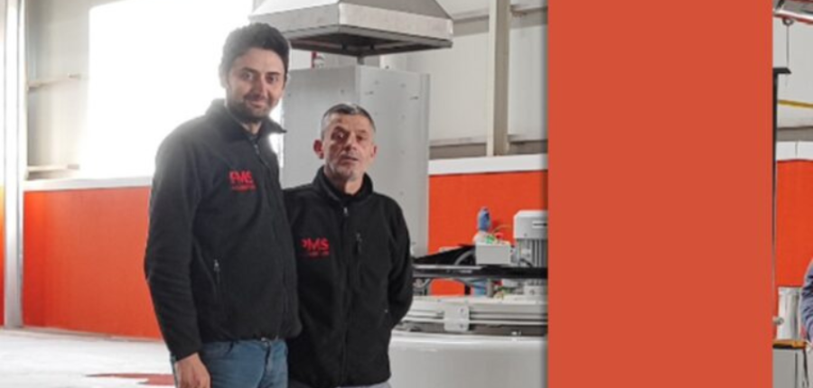
PMS Alüminyum, an aluminum extrusion company, has added a nitriding system from a North American based company that also has international locations to enhance its production capabilities and meet the increasing demand for high-quality, metal profiles across industries including automotive, construction, solar energy, defense, aerospace, and rail.
Previously outsourcing this process, PMS Alüminyum made the decision to bring nitriding operations in-house for streamlined logistics coordination, long-term cost savings, improved availability of ready-to-use dies, and faster turnaround times. Moreover, the growing number of dies to be treated made in-house processing a more viable and cost-effective solution.
The Nitrex pit-type furnace, model NX-1020, with Nitreg® controlled nitriding and Nitreg®-C controlled nitrocarburizing technologies, provides capabilities for processing H11 and H13 dies.
The system was installed in the extrusion company's new facility in November 2022 that also houses an extrusion press and powder coating lines.
Find heat treating products and services when you search on Heat Treat Buyers Guide.com
Bill St. Thomas Business Development Manager Lindberg/MPH Source: Lindberg/MPH.com
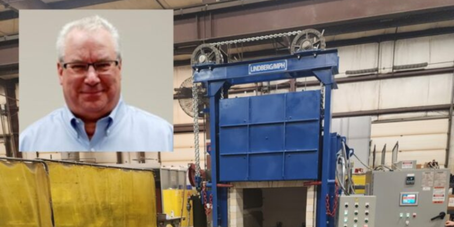
A rod overbend box furnace with powered load/unload table is being shipped from Michigan to a manufacturer. An automated actuator increases safety measures protecting the operator.
Lindberg/MPH'sfurnace has a maximum temperature rating of 2,000°F and a load capacity of 900 lbs. The workspace dimensions of the furnace are 24” x 36” x 18” and is designed for air atmosphere applications. The box furnace features an automated actuator to flip the push/pull mechanism on the load table to eliminate the operators need to manually flip it into push position. This option allows the push/pull head to retract from the furnace once the work grid is in the furnace chamber and increases operator safety by removing the need to reach into the hot furnace with a hook to flip the push/pull head.
“This furnace design is a duplicate to a previous order . . . . with the [requested] modification of an automated actuator to provide easier loading for the operator," commented Bill St. Thomas, business development manager at Lindberg/MPH.
Find heat treating products and services when you search on Heat Treat Buyers Guide.com
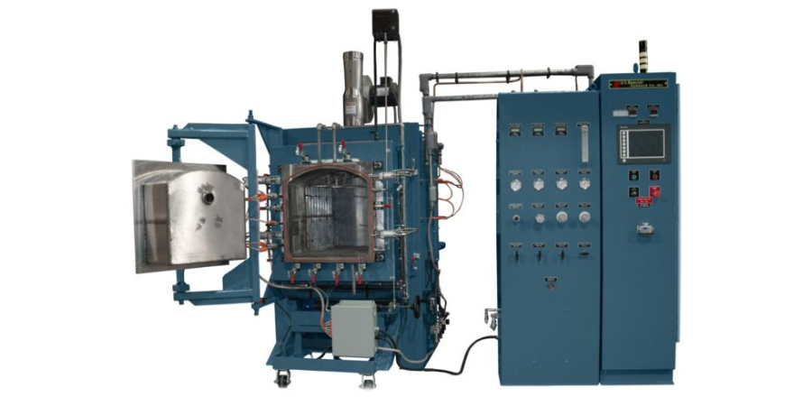
A retort furnace with an Inconel 602CA alloy retort has been shipped from Pennsylvania to a leading manufacturer of motor laminations, located in Midwestern U.S. The laminations are deployed for motors in various aerospace, military, automotive, medical and industrial fields.
L&L Special Furnace shipped the model XLC3348 XLC3348 which has an effective work zone of 23” x 23” x 36” and uniformity of ±15°F above 1,200°F. The control system includes one control loop along with six zones of heating volume that can be adjusted to achieve the required temperature gradients. The model XLC3348 satisfies all requirements for AMS2750F class 3 uniformity and type B instrumentation. The process gas lines are required copper refrigeration lines along with stainless steel to ensure a very low dew point in the process gasses.
Find heat treating products and services when you search on Heat Treat Buyers Guide.com
Nikola Tesla afirmó: <<Si quieres descubrir los secretos del universo, concéntrate en la energía, la frecuencia y la vibración.>>
Al revisar los mecanismos internos de un sistema de inducción es posible evidenciar cada uno de estos tres elementos. Los 10 pasos de esta guía servirán para apoyar a los operadores de departamentos internos de tratamiento térmico en entender los secretos de la inducción para así identificar posibles escollos en tales sistemas y dar solución a problemas comunes que se puedan presentar.
This original content article was first written by Alberto Ramirez, engineer of Power Supply and Automation at Contour Hardening, Inc. and an honoree from Heat Treat Today’s 40 Under 40 Class of 2021, for Heat Treat Today's May 2023 Sustainable Heat Treat Technologiesprint edition. Read the Spanish version below, or click the flag above right for the English version.
Alberto Ramirez Power Supply and Automation Engineer Contour Hardening, Inc.
Contact us with your Reader Feedback!
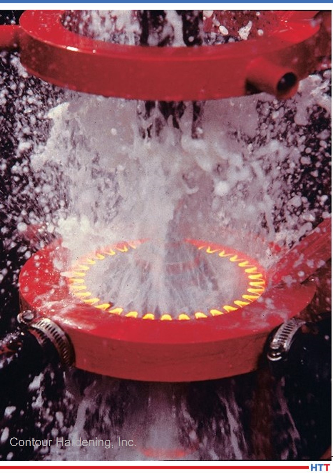
Los metales pueden calentarse mediante el proceso de inducción electromagnética, mediante el cual un campo magnético alternativo cerca de la superficie de una pieza de trabajo metálica (o conductora de electricidad) induce corrientes de Eddy (y, por lo tanto, calentamiento) dentro de la pieza de trabajo.
Los sistemas de inducción pueden llegar a ser sistemas complejos que tienen como objetivo endurecer piezas o secciones específicas de un componente mecánico, dependiendo del grado de complejidad de la pieza a tratar; para el profesional, el desafío será el diagnóstico de los problemas que se lleguen a presentar.
1. Familiarízate con el proceso
Figura 1. Proceso de endurecimiento por inducción Source: Contour Hardening, Inc.
El proceso de inducción envuelve muchas características tales como: posición de la pieza dentro de la bobina de inducción, posiciones de carga, posiciones de enfriamiento, tiempos de ciclo, potencia eléctrica aplicada, entre otras. Es importante que el profesional sea capaz de identificar la falla y la situación particular en el momento en el que se está presentando.
En algunas ocasiones las fallas no son evidentes y, por ende, es indispensable analizar la pieza que ha sido tratada; este análisis puede ser clave para entender situaciones tales como: falta de profundidad de capa por potencia eléctrica o disminución en la frecuencia de salida, entre otros posibles escenarios.
Adicional al análisis de la pieza, es vital inspeccionar la “escena del crimen” ya que muchos de los sistemas de inducción, dada la naturaleza del proceso y el peligro que implica manejar altos potenciales eléctricos, suelen ser en extremo automatizados y las estaciones de trabajo de difícil acceso para el personal, así que una buena estrategia de trabajo consiste en observar detenidamente las condiciones generales del equipo para determinar el punto de inicio para la resolución del problema.
2. Identifica los componentes principales de tu sistema de inducción, así como los mecanismos de seguridad para ciertas zonas en particular
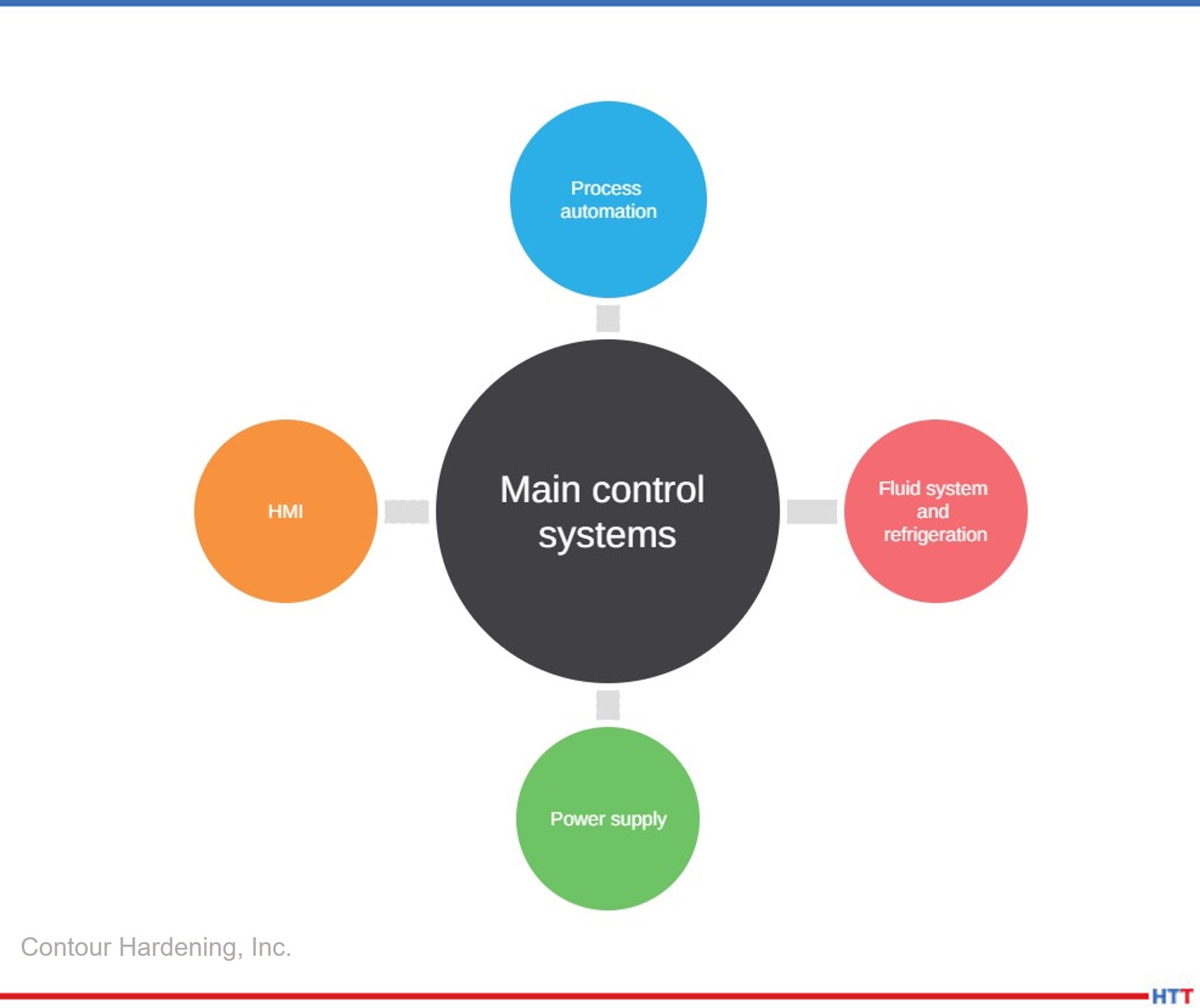
Entender la interrelación del sistema es importante para comprender qué elemento realiza cierta acción, así como los canales de comunicación entre ellos. Una vez que se genere este conocimiento, se puede asociar una falla a un componente en particular. Usualmente los sistemas de inducción se componen de los siguientes elementos:
Figura 2. Componentes de un sistema de inducción Source: Contour Hardening, Inc.
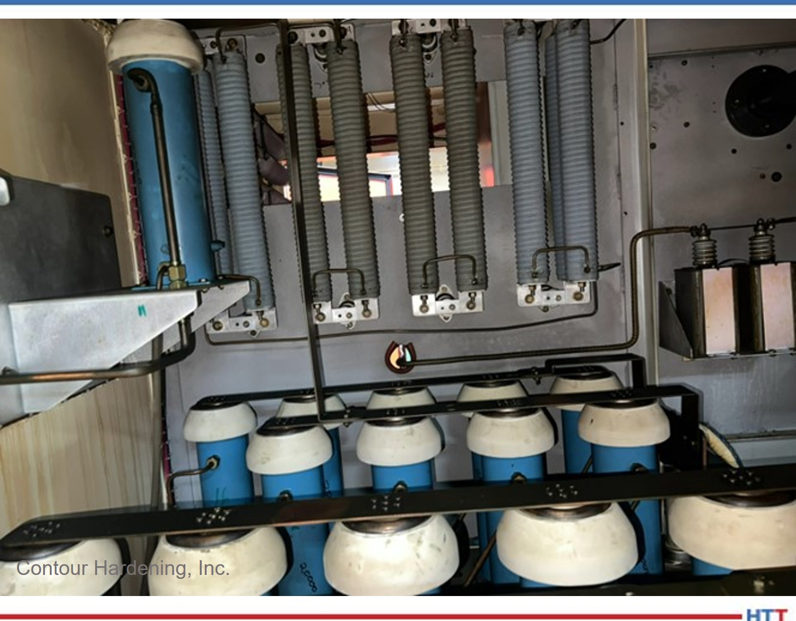
Como mencionamos con anterioridad el proceso implica altos potenciales eléctricos, y para eso la naturaleza de las fuentes de alimentación involucra dispositivos electrónicos de potencia, como capacitores eléctricos, los cuales almacenan energía y, por ende, es importante descargar eléctricamente el sistema antes de comenzar a inspeccionar un equipo.
3. Ten preparadas las herramientas necesarias para realizar un buen análisis del problema
Figura. Capacitores Source: Contour Hardening, Inc.
Al igual que cualquier problem técnico, el uso de la herramienta mecánica es indispensable al realizar algún tipo de proyecto, pero para el diagnóstico de una falla en un equipo de inducción es importante contar con:
Osciloscopio
Generador de funciones
Amperímetro
Multímetro digital y analógico.
Sondas de alto voltaje
Sin estos elementos es muy difícil llegar a un diagnóstico fiable, y la posibilidad de encontrar la falla es mínima. Por ende, tener estos medidores en buen estado y, sobre todo, calibrados nos da una perspectiva más clara del problema.
4. Verifica que los sensores del proceso, los monitores de energía y las bobinas de inducción funcionen correctamente
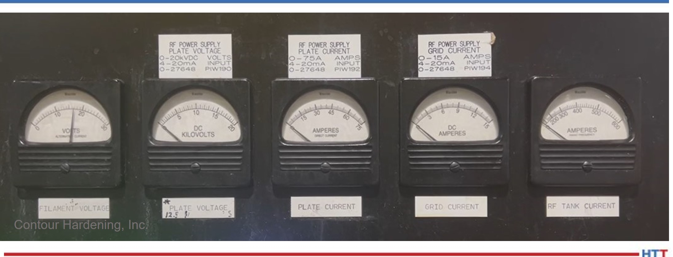
Existen distintos medidores que recogen información acerca del proceso; esta información en su mayoría puede ser visualizada a través del HMI (Human Machine Interface), y, en muchas ocasiones, una buena manera de comenzar a entender el problema es recopilar la información del proceso. Si los medidores no funcionan correctamente, te pueden llevar a conclusiones erróneas.
Verifica que los medidores de energía estén funcionando correctamente, así como tus señales de entrada y de salida.
Las bobinas de inducción son un elemento clave en el proceso de inducción ya que acorde a su geometría generan los campos magnéticos adecuados para lograr los resultados metalúrgicos esperados. Si existen fugas de agua o los elementos de transmisión eléctrica se encuentran sueltos o sucios, seguramente podrán ser la raíz del problema. Es importante comenzar a realizar el diagnóstico de la falla una vez se haya descartado este circuito en particular.
Figura 4. Ejemplo de parámetros de energía Source: Contour Hardening, Inc.
5. Realiza estudios de energía constante en tu subestación para identificar posibles problemas en tu suministro de energía, así como tiempos críticos
La energía eléctrica es la fuente principal en un proceso de inducción; las fuentes de alimentación transforman y potencializan este recurso para crear campos electrónicos lo suficientemente fuertes para generar el calor en la pieza.
Por ende, es importante descartar con evidencia que el problema en cual nos encontramos no se debe a una falla del sistema eléctrico del cual nuestro sistema de inducción forma parte. De igual manera entender cómo se comporta nuestro sistema eléctrico nos puede ayudar a generar patrones de comportamiento que puedan determinar la solución en momentos específicos en los que se lleguen a presentar.
6. Trabaja de forma metódica documentando tus movimientos y realiza un paso a la vez
Los sistemas de inducción pueden ser muy intimidantes si no has tenido experiencia previa, y, al igual que con cualquier elemento o situación, es importante abordar de manera lógica el problema analizando el modo de la falla, identificando las partes principales que interactúan en ese preciso momento, y, a partir de este análisis, documentar y realizar pequeños pasos, uno a la vez, ya que, de no ser así, es muy probable que pierdas todo el trabajo realizado y la situación empeore.
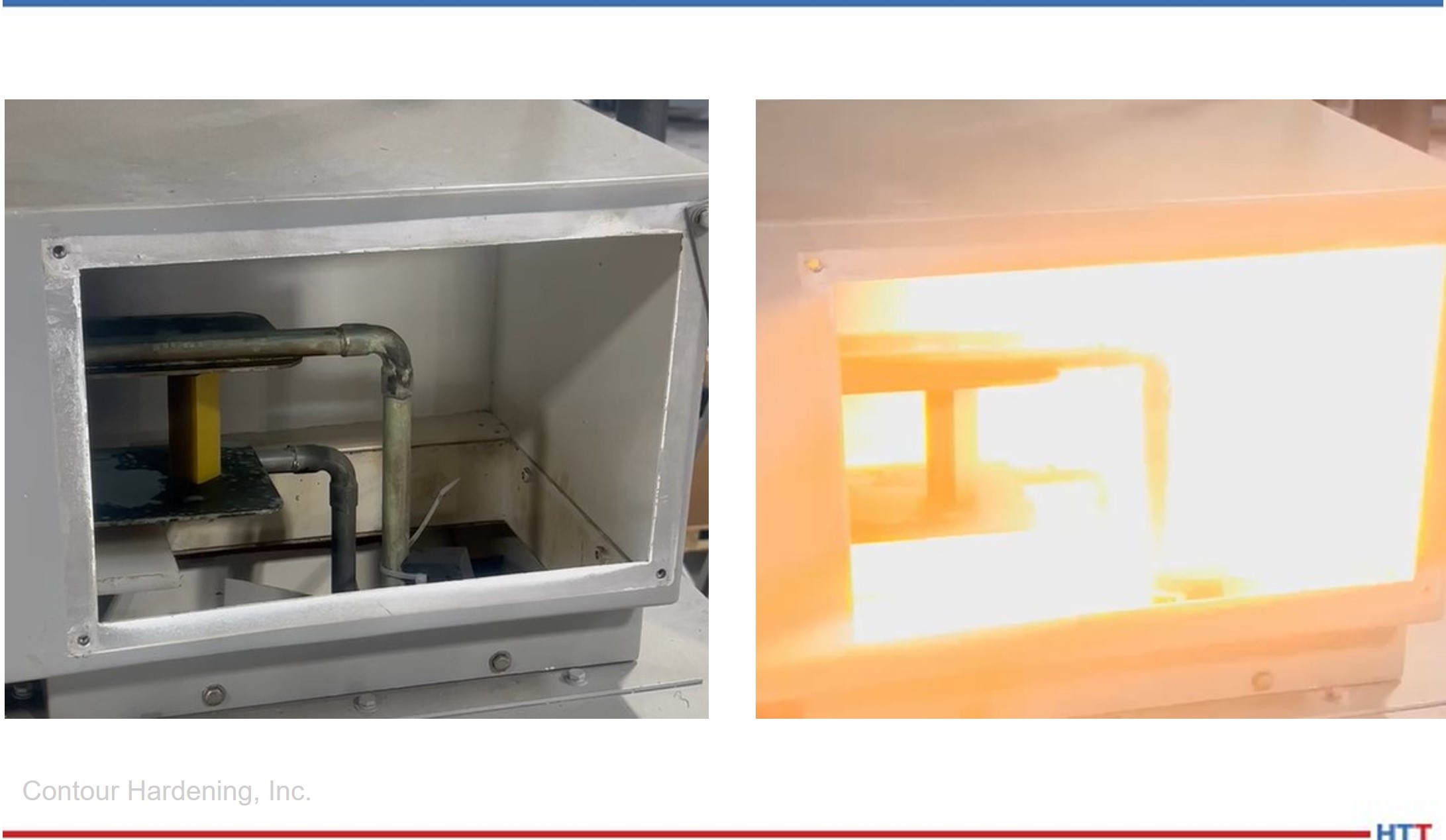
Figura 5. Antes y durante un arco eléctrico dentro de la línea de transmisión Source: Contour Hardening, Inc.
Si los movimientos no son exitosos, siempre puedes regresar a tu punto de partida e intentar otro acercamiento. La idea consiste en que el modo de la falla se mantenga estable sin importar los movimientos realizados hasta que se resuelva el problema. De esta manera lograrás contener la falla; de otra manera podrías estar dañando otros elementos sin darte cuenta.
Es muy importante entender que los procesos son secuencias que anteceden y preceden a nuevos eventos; si entiendes el proceso y, una vez resuelto el problema, ahora tienes una nueva falla, es importante analizar si esta falla es la continuación del proceso ya que, de ser así, es posible que te encuentres frente al caso de un evento que está desencadenado una serie de fallas y se haga necesario practicar un análisis más profundo. La idea general es llegar a la raíz del problema y mitigar el riesgo.
7. Intenta cualquier posibilidad relacionada con el proceso sin importar que la relación entre ésta y el problema no sea directa
Un pensamiento lógico puede resolver la mayoría de las fallas técnicas de un sistema, pero, para fallas excepcionales, es necesario utilizar la imaginación y agotar todos los recursos posibles ya que el área de interés más insignificante o el lugar menos pensado puede ser la clave para resolver un problema.
8. Conoce tus fuentes de alimentación
Uno de los factores claves en cualquier equipo de inducción son sus fuentes de alimentación. Las fuentes de alimentación son equipos que no requieren un mantenimiento tan arduo en comparación con otros sistemas en la industria, pero, de no presentarse las condiciones mínimas de mantenimiento, pueden generar altas pérdidas para la organización.
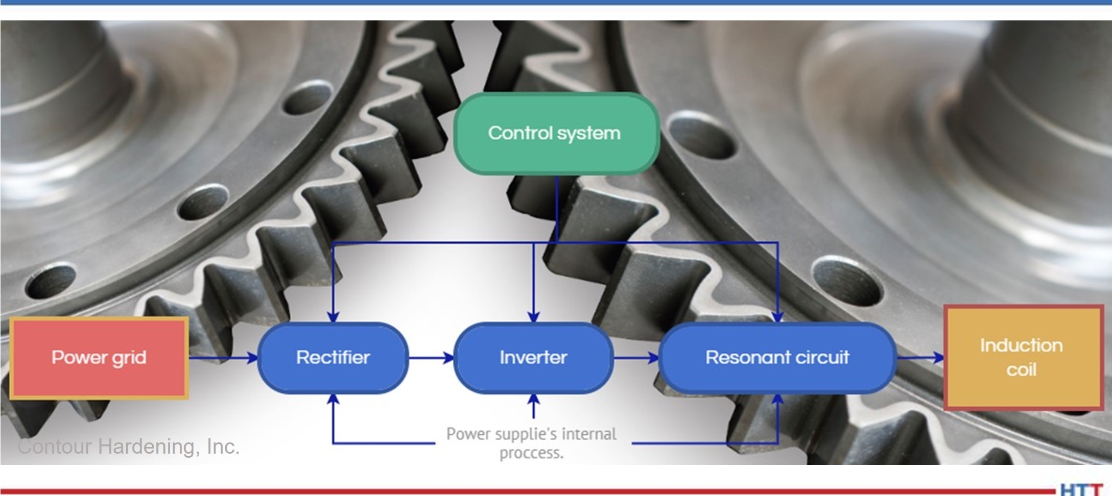
Figura 6. Diagrama de flujo del proceso eléctrico en una fuente de alimentación Source: Contour Hardening, Inc.
En los casos en los que el problema se encuentra en las fuentes de alimentación, es vital que se siga el mismo proceso metódico previamente descrito. Entender cómo funciona el proceso de transformación de la energía te dará una ventaja, al igual que conocer los componentes empleados o el tipo de tecnología utilizado en el proceso de rectificación, en la inversión (estado sólido o tubos de electrones) y en el circuito resonante. Generalmente las fuentes de alimentación siguen el siguiente patrón de transformación (Figura 6).
9. Identifica las partes críticas de tu equipo de inducción y prepara un inventario de éstas
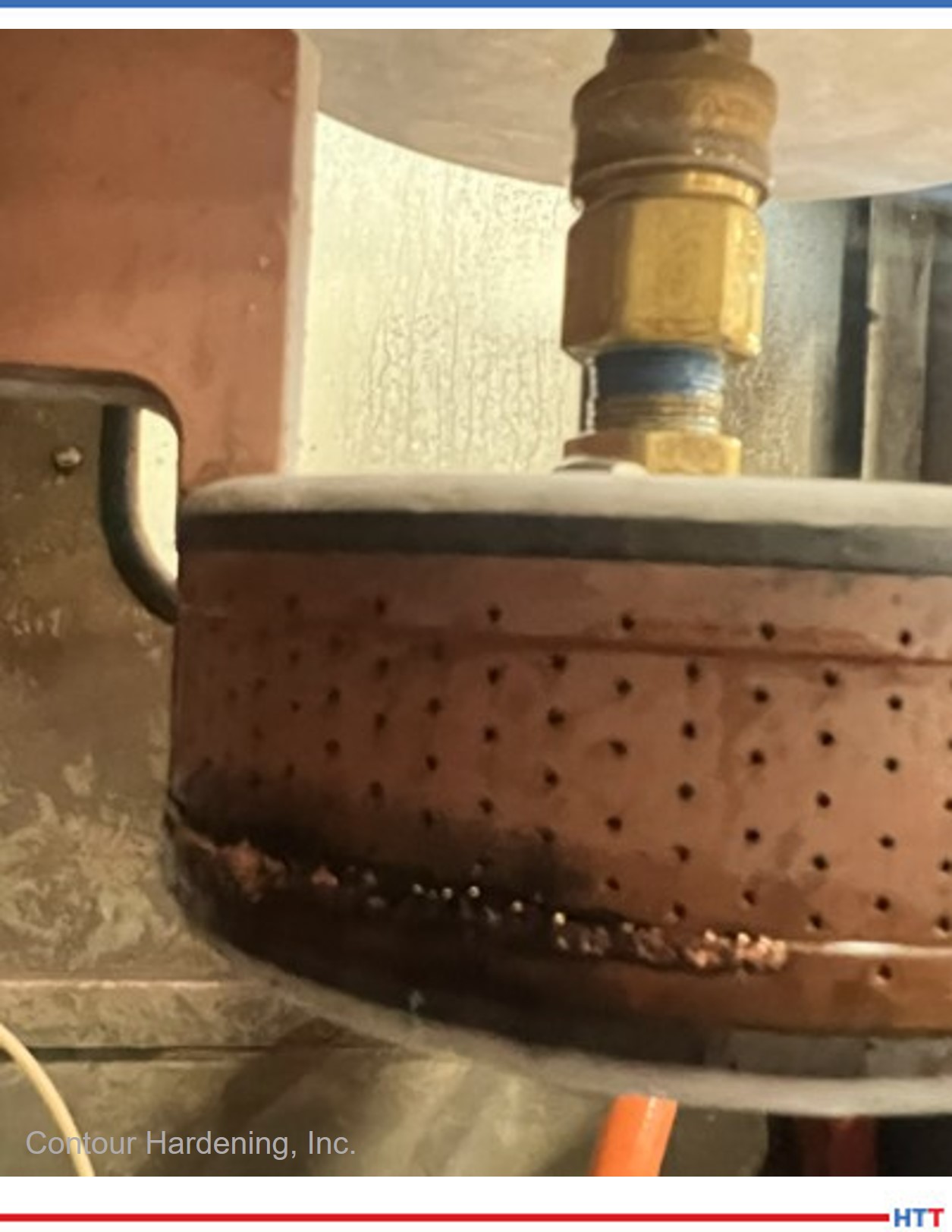
Figura 7. Daño en una bobina de inducción Contour Hardening, Inc.
Usualmente los componentes que forman parte de las fuentes de alimentación son difíciles de conseguir dependiendo de la antigüedad de tu equipo, y con la reciente crisis de microchips en el mercado, existen tiempos de entrega muy largos para los elementos de control y automatización; de igual manera, los precios de los mismos se han disparado. Por ende, es vital que exista una lista de partes críticas y un inventario de éstas.
Adicionalmente a los elementos descritos, las bobinas de inducción suelen ser elementos muy característicos e importantes en el proceso de inducción. Éstas bobinas son elementos complejos que han sido diseñados exclusivamente para la pieza, por lo que su fabricación puede tomar varias semanas, y es importante tomar las precauciones necesarias para mantener un movimiento de mantenimiento constante.
10. Realiza mediciones preventivas al sistema para generar un patrón de comportamiento
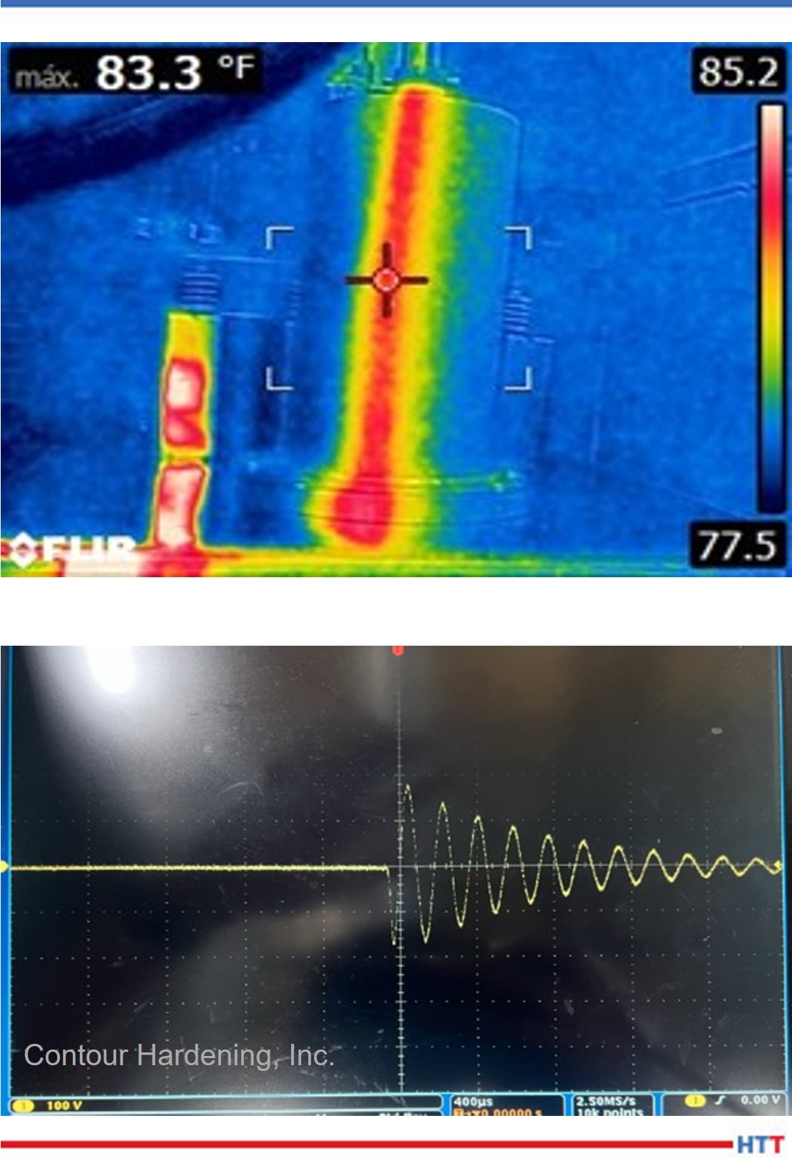
Figura 8. Ejemplo de posibles mediciones Contour Hardening, Inc.
Cuando el sistema se encuentre trabajando en óptimas condiciones, genera un plan de medición el cual te permita recopilar información de puntos específi cos dentro del sistema. Una vez que se vuelva a presentar una nueva falla puedes comparar las mediciones de falla contra las del buen funcionamiento. Algunos ejemplos de mediciones pueden ser:
Temperatura
Voltaje
Corriente eléctrica
Resistencia y capacitancia
Formas de onda
En resumen
Una metodología de trabajo ordenada y documentada, un buen catálogo de piezas de recambio, junto con las herramientas de trabajo necesarias, pueden ser elementos clave para entender un problema y, lo que es más importante, resolverlo de forma eficaz.
Es vital que los profesionales se capaciten de manera constante para mejorar los tiempos de paro debido a fallas en los sistemas de inducción. La capacitación relacionada con procesos metalúrgicos sería una buena forma de complementar tus habilidades de resolución de problemas permitiéndote interpretar las características de los sistemas de inducción, al igual que de los elementos que los componen.
Bibliografía
Valery Rudnev and George Totten, ed., ASM Handbook Volume 4C: Induction Heating and Heat Treatment, (Materials Park, OH: ASM International Heat Treating Society, 2014), 581- 583
Sobre el autor: Alberto C. Ramirez es ingeniero en Mecatrónica egresado del Instituto Tecnológico Nacional de México Campus León con una maestría en Administración de Tecnologías de la Información por el Instituto Tecnológico de Monterrey. Cuenta con más de 8 años de experiencia en fuentes de alimentación, gestión de proyectos, mantenimiento y automatización. Actualmente se desempeña como ingeniero de fuentes de alimentación y automatización en Contour Indianapolis. Alberto inició su carrera en la fi lial de Contour en México y debido a su dedicación forma parte del staff en los Estados Unidos.
He is also an honoree from Heat TreatToday's 40 Under 40 Class of 2021.