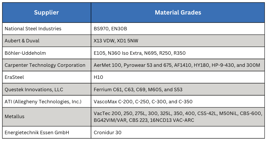
Acero Descarburizado: Crítico para el Endurecimiento por inducción de Cuchillas Rotativas
Para las operaciones de tratamiento térmico internas (in house), el objetivo principal es producir un producto confiable con un desempeño consistente en servicio. Sin embargo, la cadena de suministro y los procesos especializados pueden generar factores que comprometen la consistencia. En este artículo, Heat Treat Today destaca la importancia de contar con material base consistente para el tratamiento térmico por inducción interno de National Steel Rule, y cómo se puede implementar el proceso esencial de descarburización controlada en la planta proveedora de acero.
Este artículo informativo se publicó por primera vez en Heat Treat Today’s April 2026 Annual Induction Heating & Melting print edition. Traducido por Ana Laura Hernández Sustaita.

Si tiene comentarios o preguntas sobre este artículo, háganoslo saber en: editor@heattreattoday.com.
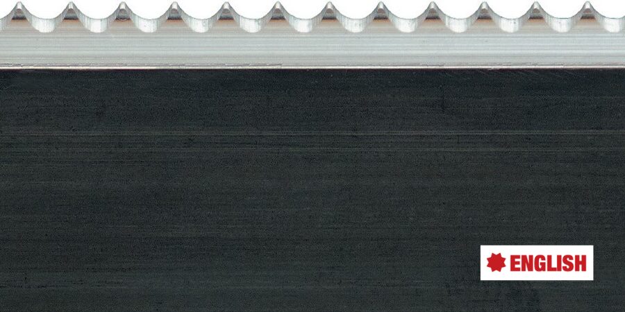
To read this article in English, click here.
Introducción: Regla de Acero que se Dobla
La empresa National Steel Rule produce reglas de corte rotativas para la industria del cartón corrugado. Ubicada en Linden, Nueva Jersey, la empresa suministra productos a las industrias de troquelado a nivel mundial. La compañía ha establecido altos estándares de abastecimiento, investigación y pruebas de material para sus reglas de corte, además de contar con un completo laboratorio con equipos de troquelado rotativo y plano.
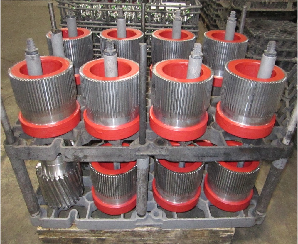
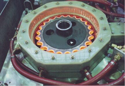
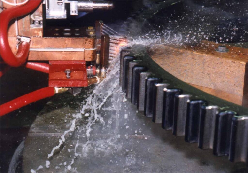
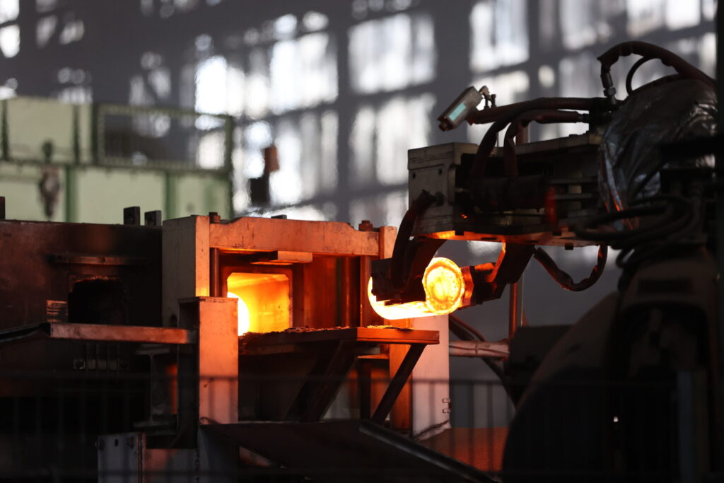
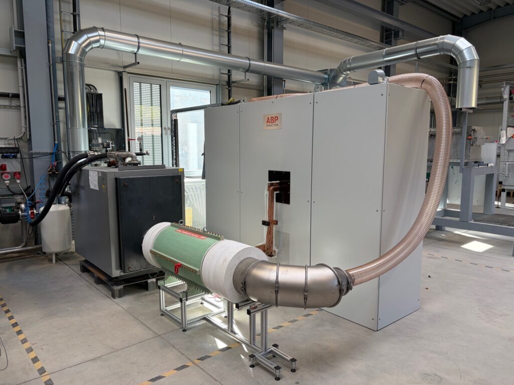
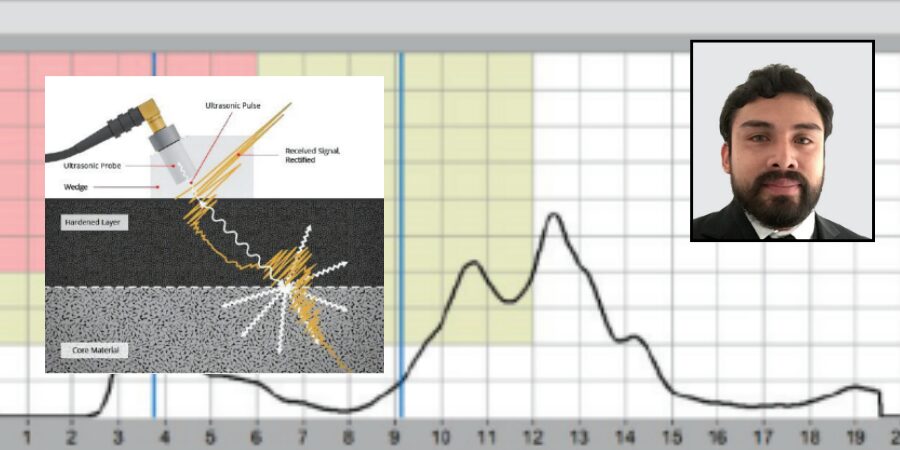
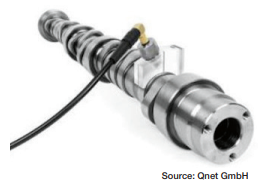
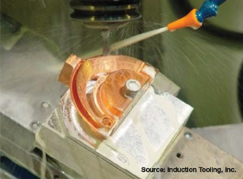
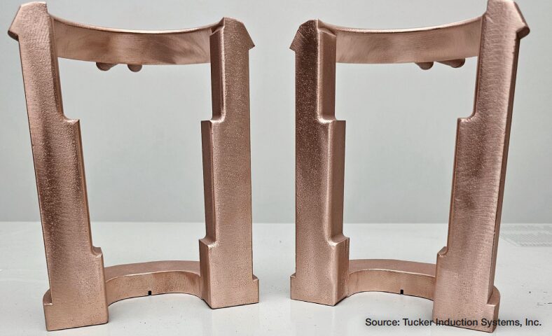
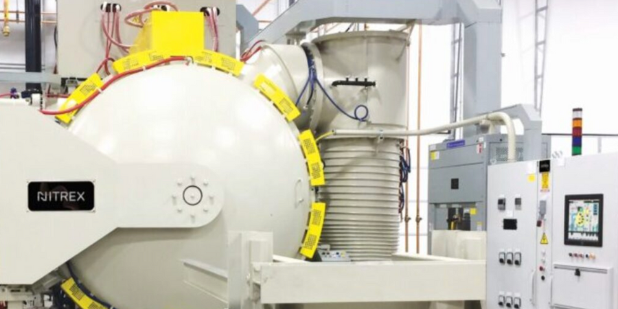
Su regla de acero se adquiere de una planta proveedora de acero que realiza una descarburización controlada en todo el material. Cuando National recibe el material, procesa el acero para generar los dientes, empleando endurecimiento por inducción como parte del proceso (ver la imagen principal al inicio de este artículo). La regla de corte terminada se vende posteriormente a fabricantes de troqueles de regla de acero, quienes montan estas cuchillas junto con una goma de expulsión sobre tableros de madera cortados con láser. El fabricante debe asegurarse de que las cuchillas de las reglas estén libres de defectos, ya que incluso grietas microscópicas se abrirán durante el troquelado.
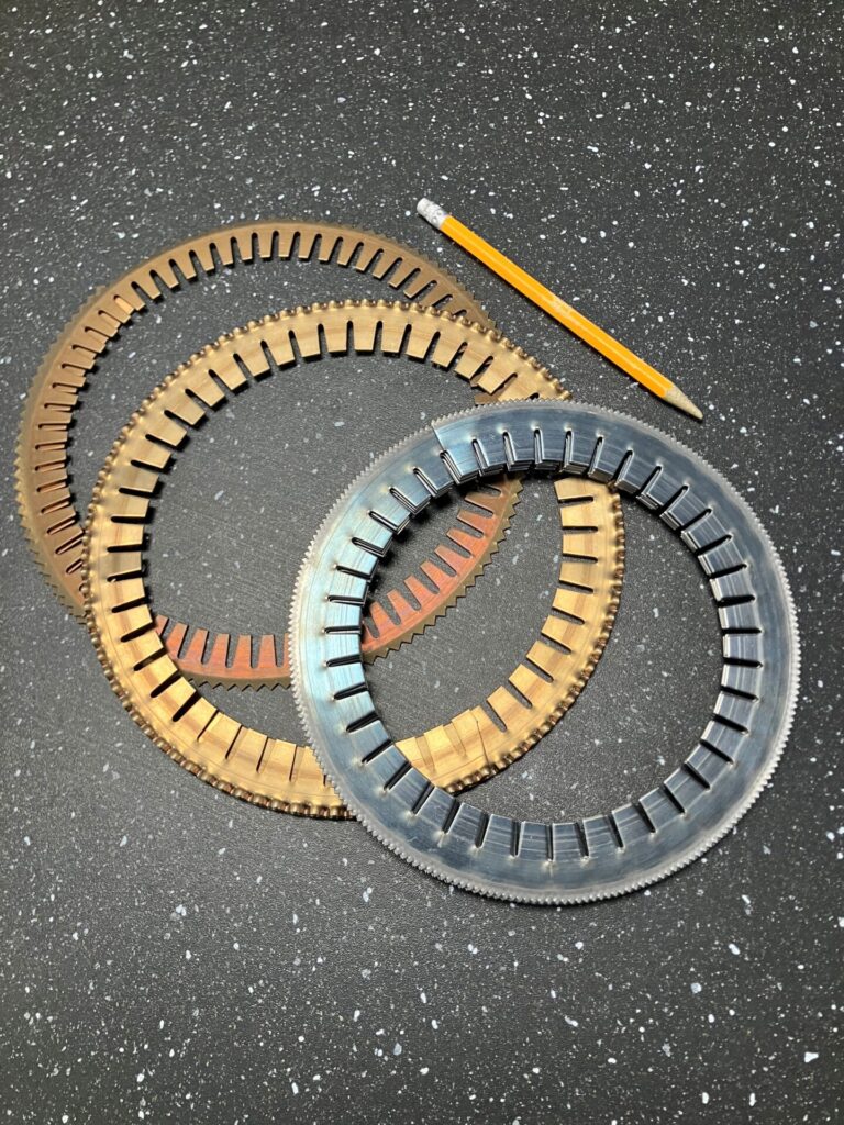
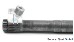
Figura 1. Regla de acero doblada de diámetro pequeño | Crédito de la imagen: National Steel Rule
Las cuchillas rotativas y otros productos de National dependen de la compra de acero descarburizado. “La flexibilidad y la conformabilidad son fundamentales”, afirma Ed Mucci, presidente de la empresa, y Alexander Heucke, ingeniero en jefe. La regla de corte debe doblarse para formar una cuchilla circular; durante el servicio, la cuchilla rota para cortar el material corrugado. La geometría de la curvatura puede ser extrema, llegando a doblarse hasta un diámetro interior de 7 pulgadas. Por lo tanto, la compra de acero descarburizado es crítica para el negocio del fabricante. Actualmente, National obtiene el material a nivel internacional. Mucci explica: “Los fabricantes no utilizan grandes cantidades de acero descarburizado, lo que dificulta su abastecimiento, al menos a nivel nacional”.
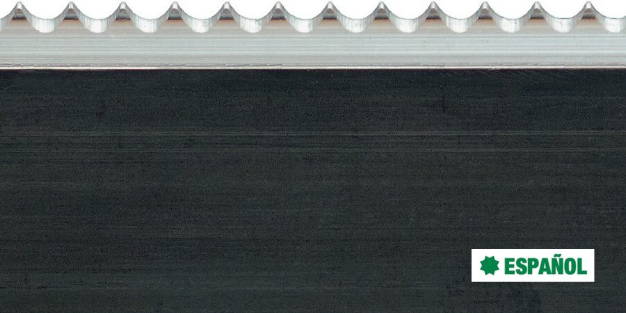
El material para las reglas rotativas suele ser acero al carbono C36 (SAE 1036) a C50 (SAE 1050) con un rango de dureza de 32–34 HRC. Mucci y Heucke señalan que el acero que utilizan presenta una capa de descarburización total de 0.0005” de profundidad, con una descarburización parcial adicional de al menos 0.0005”–0.00075”. Esto garantiza que cuando una regla se dobla, la superficie se elongue en lugar de agrietarse. Doblar la regla es, en sí mismo, una prueba para comprobar si se ha descarburado correctamente, y las pruebas metalúrgicas sirven como verificación de control de calidad para garantizar que los proveedores estén produciendo los niveles adecuados de descarburización.
Endurecimiento Preciso por Inducción de los Dientes
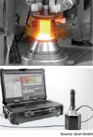
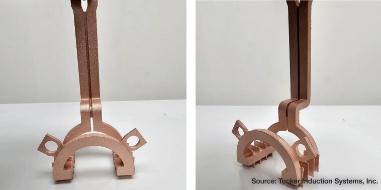
Si bien el doblado es esencial para formar la curvatura apropiada, los dientes deben ser resistentes al desgaste y la rotura. La regla de corte rotativa de National tiene una expectativa de desempeño de al menos 750,000 impresiones en papel, que es en sí mismo un material altamente abrasivo. Para lograrlo, las operaciones de tratamiento térmico internas endurecen por inducción el borde de la regla, garantizando una larga vida útil del troquel.
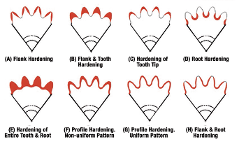
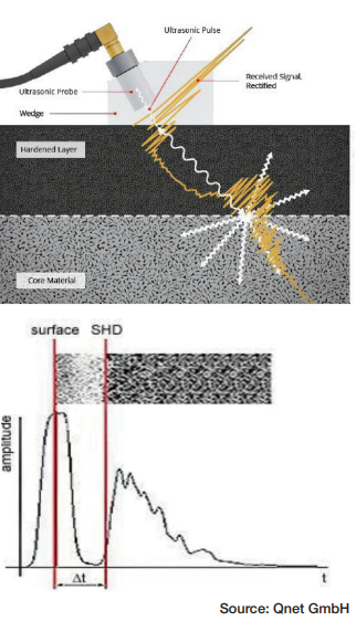
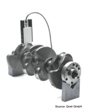
Existen dos métodos usados para endurecer los dientes. El método principal es maquinar el perfil de la tira de acero y posteriormente endurecer por inducción el borde. Posteriormente los dientes son rectificados. “Esto nos da un mejor control sobre la profundidad de endurecimiento”, comenta Mucci y Heuke. El segundo método consiste en endurecer por inducción después de rectificar los dientes. “Debemos asegurarnos de que el endurecimiento de los dientes no sea muy profundo, ya que esto puede afectar la capacidad de doblado”. El endurecimiento por inducción implica ciclos muy cortos, y por lo tanto requiere un control minucioso del proceso para garantizar resultados consistentes. Entre los métodos de control del proceso se utilizan crayones indicadores de temperatura, que se funden a una temperatura específica. También se realizan pruebas de dureza.
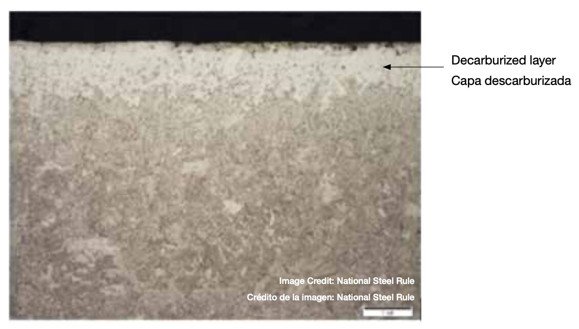
Figura 2. Detalle de la capa descarburizada | Crédito de la imagen: National Steel Rule
Revisitando la Descarburización
“Generalmente se intenta prevenir la descarburización o incluso agregar carbono a la superficie”, comenta Mark Hemsath, consultor ejecutivo en WINGENS CONSULTANTS y reconocido experto e innovador en la industria del tratamiento térmico. “La descarburización a menudo ocurre accidentalmente en sistemas de recocido mal diseñados, especialmente en hornos de tratamiento continuo.”
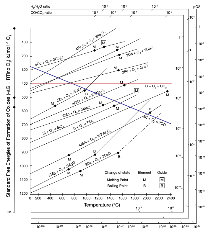
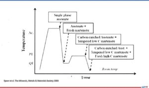
Figura 3. Diagrama de Ellingham que muestra la relación hidrógeno-vapor de agua, clave para una descarburización controlada exitosa.
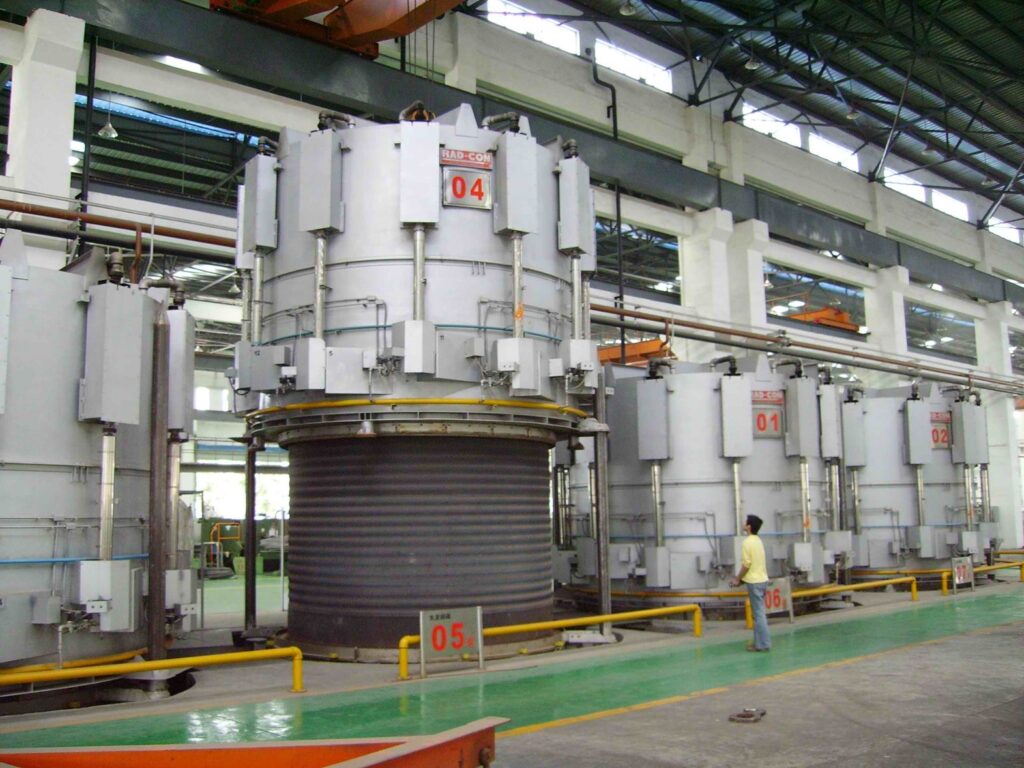
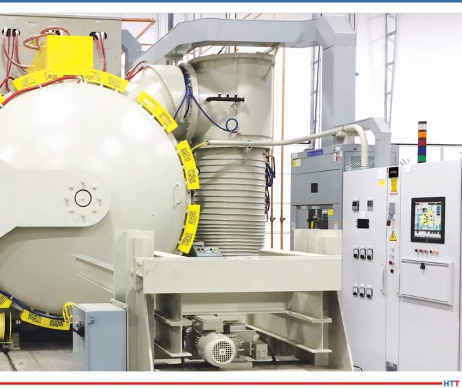
Figura 4. Horno típico de recocido tipo campana. | Crédito de la imagen: RAD-CON
El oxígeno en forma de aire o de vapor es la clave del proceso de descarburización. Menor porcentaje de carbono en la superficie indica un acero más blando y maleable, y si bien el arte de un proceso de descarburización controlada es bien conocido, puede resultar un desafío. El proceso de descarburización suele realizarse por debajo de 1500°F (815°C). “El método preferido es usar vapor de agua o vapor como fuente de oxígeno”, señala Hemsath. Esto se basa en la estabilidad de la relación hidrógeno-vapor de agua (H2/H2O) derivada del diagrama de Ellingham. Estas relaciones H2/H2O indican las propiedades no oxidantes de la mezcla gaseosa, lo que permite que actúe como agente reductor de carbono en la atmósfera del horno. La mayoría de las empresas fabricantes de hornos pueden proporcionar el equipo necesario y personalizar las dimensiones para hacerlos adecuados para este proceso especial. Estos hornos suelen ser de tipo campana o tipo foso con retorta.
Dos Métodos para Controlar la Descarburización
Existen dos formas de realizar intencionalmente un proceso de descarburización. La primera consiste en descarburar todo el producto. En este método, la descarburización se aplica de manera uniforme en toda la superficie de la lámina o bobina. “Este acero laminado en frío generalmente con menor contenido de carbono, se utiliza en electrodomésticos que requieren una buena adherencia del esmalte”, explica Hemsath. Empresas como U.S. Steel y AK Steel (ahora parte de Cleveland-Cliffs) han utilizado esta forma de descarburización controlada.
Otra forma es la descarburización selectiva en la superficie. Hemsath explica: “Si la descarburización solo se requiere en los bordes, se podrían mantener las bobinas enrolladas firmemente, por lo tanto, la descarburización afectaría principalmente a los bordes. Se produciría una pérdida de carbono que disminuiría hacia el centro de las superficies enrolladas”.
Conclusión
“El acero descarburizado tiene mucha demanda, ya que la mayoría de las industrias buscan endurecer y templar los aceros que utilizan”, indica Mucci. De hecho, la prevención de la descarburización del acero es más común y suele destacar en ferias industriales, presentaciones técnicas y publicaciones de procesamiento térmico. Sin embargo, existen productos que dependen de la descarburización intencional para funcionar correctamente.
La descarburización controlada en la planta proveedora de acero presenta desafíos, en parte porque lograr una descarburización exitosa y consistente no suele ser económicamente viable para el mercado norteamericano de tratamiento térmico. Estos desafíos abarcan problemas de acceso regional, acceso a nichos de mercado, necesidades de selección de equipos y ejecución de procesos técnicos.
La experiencia de National destaca los desafíos que enfrentan las plantas proveedoras de acero de América del Norte para proveer a las empresas de tratamiento térmico interno, acero descarburizado de forma fiable y bien controlada que mantenga su vida útil.
Agradecimientos: Heat Treat Today agradece a Dan Herring, The Heat Treat Doctor®, The HERRING GROUP, Inc., quien fue fundamental en el desarrollo de este artículo.
Para más información: Contacte con Heat Treat Today’s Editorial Team en editor@heattreattoday.com.
La imagen principal: Regla rotativa RP8 con borde endurecido | Crédito de la imagen: National Steel Rule