Optimized heat treat performance starts long before parts reach the furnace. In this Technical Tuesday installment, Chris Tivnan of SAFECHEM North America Inc. highlights how SEW-EURODRIVE‘s switch to solvent-based cleaning enabled faster cycles, reliable residue removal, and consistent results.
This informative piece was first released in Heat Treat Today’sApril 2026 Annual Induction Heating & Melting print edition.
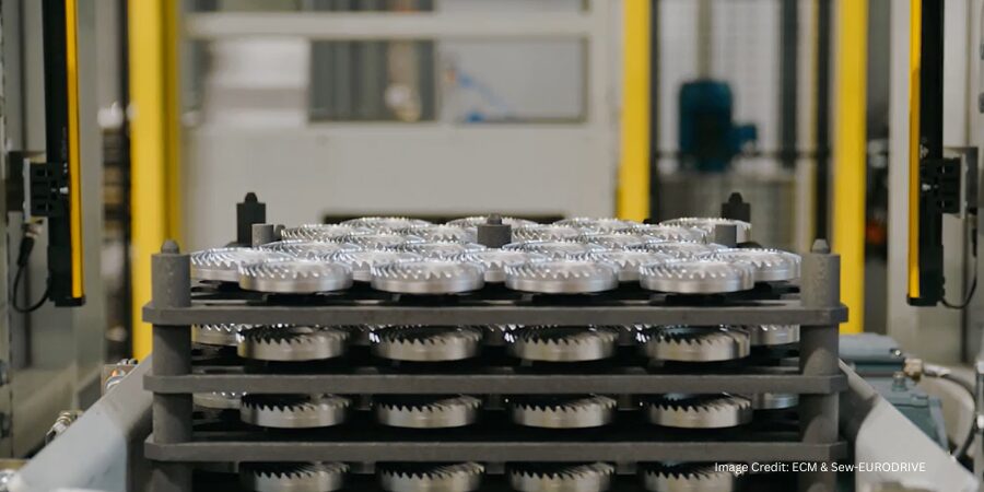
In the world of industrial motion systems, precision, durability, and efficiency are non-negotiable. SEW-EURODRIVE, a manufacturer of advanced drive solutions, focuses on delivering performance-driven gearboxes and industrial drives that power everything from airport walkways and roller coasters to heavy-duty conveyors in manufacturing plants. At the heart of this capability lies the careful heat treatment of steel components, specifically gears and pinions, processed to exacting standards for strength and longevity.
From Atmospheric Carburizing to New Demands
Since 2002, SEW-EURODRIVE had relied on a well-established process: aqueous cleaning, followed by atmospheric carburizing, oil quenching, and a second aqueous cleaning process. The approach was reliable but not without limitations.
Their gas-fired furnaces demanded costly maintenance, such as re-bricking the hot zone, replacing furnace rails, and frequently tuning the burners to ensure safety. Oil quenching created a messy environment and required an additional post-quench wash. For smaller parts, the process was also highly labor-intensive. Operators had to manually build furnace loads, then shot blast parts after heat treatment. Processing several hundred thousand gears and pinions per year in this way translated into significant time and manpower.
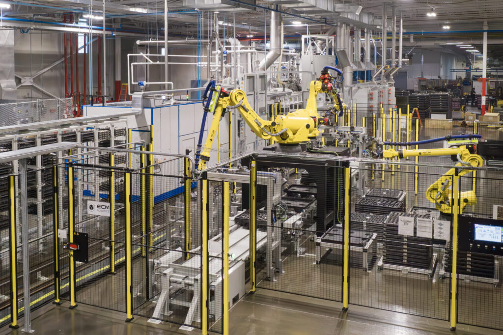
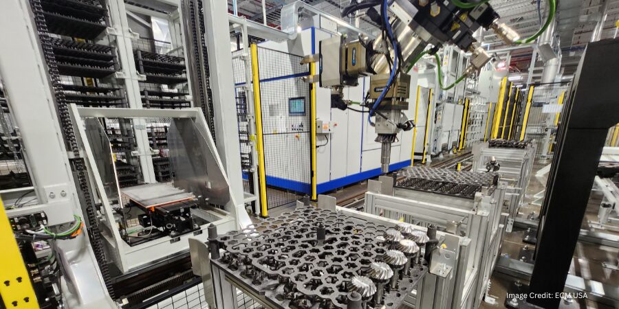
Figure 1. Advanced robotics drive SEW-EURODRIVE’s fully automated cleaning and vacuum carburizing line — delivering higher throughput, consistency, and precision. Image Credit: ECM & SEW-EURODRIVE
SEW-EURODRIVE maintained five atmospheric furnaces on site, but to improve efficiency they envisioned a new setup: continuing to run large parts in the existing furnaces while shifting smaller, higher-volume gears and pinions to a vacuum carburizing line with robotic automation.
Why Vacuum Carburizing and Why Cleaning Matters
The ECM NANO vacuum carburizing system, designed for small batch sizes, allowed SEW-EURODRIVE to integrate robotic loading and unloading, a crucial step toward automation. Vacuum carburizing also offered tighter process control, reduced distortion, and more consistent results than atmospheric methods.
However, vacuum carburizing is unforgiving when it comes to cleanliness. Unlike atmospheric furnaces, which can tolerate some surface contamination, vacuum furnaces demand perfectly clean parts. Any residue from machining oils, coolants, or metal shavings risks compromising part quality and furnace integrity.
This is where cleaning — often treated as a secondary or preparatory step — became the cornerstone of SEW-EURODRIVE’s process reengineering. The HEMO hybrid cleaning machine, capable of running both aqueous and solvent programs, was selected to provide maximum flexibility. The system runs on the modified alcohol solvent DOWCLENE™ 1601.
Overcoming Initial Concerns
For a company committed to environmental responsibility, introducing a solvent-based process was not taken lightly. Concerns about waste disposal, flammability, and worker exposure were thoroughly evaluated. However, the hermetically sealed HEMO cleaning system, designed for safe solvent handling and minimal emissions, provided the reassurance the Environmental Health and Safety (EHS) team required.
Beyond the demands of vacuum carburizing itself, another decisive factor for solvent cleaning is the use of carbon fiber composite (CFC) fixtures in the cleaning and heat treat line. Lightweight yet highly durable, these fixtures make automated handling of smaller batch sizes possible. However, their porous structure tends to absorb liquids during cleaning. Any residual moisture or oils can later release in the furnace, risking damage to the hot zone and compromising part quality.
Compared with aqueous cleaning, solvent cleaning evaporates completely and removes absorbed residues far more effectively, leaving both parts and fixtures perfectly dry. In this way, solvent cleaning makes automation with CFC not only feasible but reliable. Multiple test cycles, conducted both at HEMO’s and ECM’s facilities, confirmed the performance: only solvent cleaning reliably removed the oils and coolants that could otherwise lead to furnace fouling or part discoloration.
A Technical and Operational Leap Forward
By March 2025, the fully integrated cleaning and vacuum carburizing line was in full production. The new process — solvent cleaning, vacuum carburizing, gas quenching, and tempering — represented a dramatic leap forward, both technically and operationally.
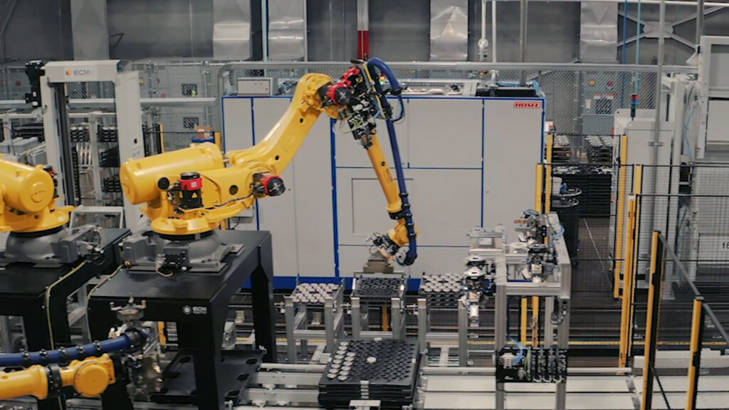
Figure 2. Full integration of HEMO cleaning and ECM vacuum technology enables a streamlined, automated workflow. | Image Credit: ECM & SEW-EURODRIVE
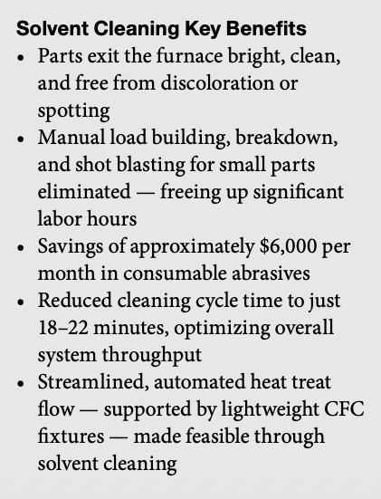
Parts now exit the furnace bright and clean, with no spotting or discoloration. The smaller batch sizes of the vacuum furnace system enable robotic loading, helping to achieve a streamlined, automated heat treat flow, especially critical for high-volume parts.
Manual processes once needed to build and break down furnace loads, as well as to shot blast parts post-treatment, have been fully eliminated for small components. This shift has not only freed up significant labor hours for larger parts that still require traditional handling but has also eliminated roughly $6,000 per month in consumable abrasive costs.
“In the past, it would take us two weeks to process an order of 25,000 gears and 25,000 pinions through the manual steps. That manpower is no longer needed on a very large section of our product family,” explained Chris Rollins, SEW-EURODRIVE’s Heat Treat Supervisor.
The hybrid cleaning system, equipped with aqueous and solvent cleaning technologies, was selected to provide maximum flexibility in removing different types of machining soils. This versatility ensured that the system could adapt to any future cleaning requirements. In practice, after extensive testing, SEW-EURODRIVE determined that solvent-only cycles best matched the needs of their vacuum carburizing line, offering the shortest cycle times and most consistent cleaning results.
While hybrid programs run in about 30 minutes and aqueous cycles in around 50 minutes, solvent-only cycles achieve the same high cleanliness in just 18 to 22 minutes — fast enough to keep pace with furnace loading and optimize overall throughput.
Gas quenching has also replaced oil quenching, eliminating the need for a second aqueous wash and the associated challenges of soap concentrations, rinses, and tank maintenance. Beyond weekly solvent checks and routine discharges, maintenance requirements for the cleaning machine remain low.
“With aqueous cleaning, it’s always a delicate balance to get the right amount of soap for cleaning without leaving spots,” explained Rollins. “With solvent cleaning, we don’t see spotting, rust, or any contaminants. The vacuum process also helps reduce distortion, so we have more consistent parts.”
Cleaner Start, Cleaner Finish
Optimizing heat treat results meant looking beyond the furnace for SEW-EURODRIVE. With vacuum carburizing, cleanliness is no longer optional — it’s critical. The integration of the hybrid cleaning technology unlocked the full advantages of the vacuum carburizing furnace system: automation, speed, quality, and consistency.
This process reengineering experience demonstrated that heat treat success starts far earlier, in the cleaning phase, and that true optimization comes from understanding how each part of the system supports the others. In this case, the cleaner the start, the cleaner the finish. “The new system has made us faster, leaner, and more confident in every part that leaves the line. Solvent cleaning wasn’t just a switch — it was the key to making vacuum carburizing work,” concluded Rollins.
About The Author:
Chris Tivnan Sales Manager SAFECHEM North America Inc.
With two decades of experience in the chemical industry, Chris Tivnan of SAFECHEM North America Inc. counsels manufacturers on the right choice of cleaning agent and their parts cleaning operation. He also manages relationships with regional distributors as well as local OEMs/OEAs.
Manual loading and batch transfers are giving way to robotic material handling in modern heat treat operations. In this Technical Tuesday installment, Dennis Beauchesne, general manager of ECM USA, examines how automation improves repeatability, boosts productivity, and reduces operator exposure to hazardous conditions near furnace hot zones — and how robotics, vision systems, and mobile transport technologies are helping heat treat facilities build safer and more efficient production environments.
This informative piece was first released in Heat Treat Today’sApril 2026 Annual Induction Heating & Melting print edition.
Robotic material handling is rapidly transforming modern heat treat operations traditionally dependent on manual loading and batch transfer. As heat treaters face increased pressure to improve throughput and working conditions while maintaining strict quality standards, automation has become a strategic investment.
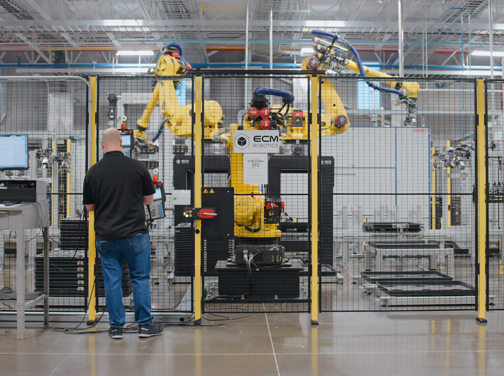
Figure 1. SEW-EURODRIVE (Lyman, SC) robotic integration by ECM Robotics features a rear robot and pallets on the left and open area on the right for dunnage storage and management | Image Credit: ECM USA
Heat treat material handling is more than simple part movement. Parts must first be positioned onto fixtures or loaded into bins which are transferred, placed into the furnace, and then moved again for quenching and/or tempering — sometimes under undesirable conditions depending on the installed technology. Additionally, a robot needs to store dunnage in the designated robot area during the processing of the parts in the furnace and then reuse it when the parts are unloaded from the furnace. Dunnage can also be stored in the heat treat area and handled by automation (Figure 1). Robotics and automation promote efficiency and repeatability in this process, which is difficult to achieve with manual operations.
Robotic Advantages
The most significant advantages of robotic material handling are repeatability, consistency, and reduction of work force. Robots execute the same motions cycle after cycle, which ensures uniform loading and proper spacing between parts within fixtures or baskets. For example, in vacuum furnaces, correct part placement is essential to achieving even heat distribution and minimizing distortion. Automated loading eliminates error caused by human fatigue or procedure changes, leading to more consistent and desirable metallurgical results and reduced scrap/re-work.
Improved throughput and increased productivity are other major justifications for robotic integration. Heat treatment can hold-up manufacturing due to cycle times and variable material flow. Robotic systems streamline loading and unloading, reduce wait time between cycles, and allow furnaces to operate at optimal capacity. In high-volume environments, robotics can be managed with upstream machining and downstream finishing processes to create a continuous, automated production line. This level of integration shortens lead times and supports just-in-time manufacturing.
Safety is equally if not more important, as handling baskets or fixtures near hot zones increases operator risk of burns and injuries. Integrating robotics improves workplace safety by removing operators from direct exposure to these hazards. This solution also addresses labor shortages by allowing skilled personnel to focus more on process optimization and quality control rather than repetitive physical tasks.
Specifically in vacuum heat treatment, robotic systems are particularly beneficial. Vacuum furnaces require precise loading to maintain thermal uniformity and protect sensitive components. Automated loaders can transfer loads between heating chambers, quench cells, and temper furnaces in a continuous process flow that minimizes temperature loss and handling delays. Metallurgical results (e.g., hardness, case depth, distortion) are also directly influenced. This is especially helpful for critical and sensitive applications, such as aerospace components and medical devices.
Robotic Components Explained
For manufacturers with in-house heat treat or commercial shops processing multiple part types, the flexibility to program and handle a wide range of part geometries, weights, and batch sizes is vital for efficient operations. Quick-change grippers, adaptive tooling, mobile transport, and vision systems are key robotic components to achieve this goal (Figure 2). Vision systems of today are far more advanced in assisting with the programming phase than those from just a few years ago.
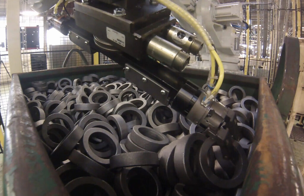
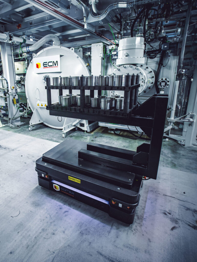
Figure 2. ECM Robotics manipulating parts | Image Credit: ECM USAFigure 3. AGV (automated guided vehicle), a portable robot that follows a path, delineated physically (e.g. lines on the floor) or through other guide posts (e.g. radio waves, magnets, lasers) | Image Credit: ECM USA
After the load building, automated mobile robots (AMR) or automated guided vehicles (AGV) can also be used to transport loads to and from the furnace. These mobile robots are integrated into factories to automate the transport of loads between different areas without requiring fixed infrastructure (rails or magnetic strips). This system coexists easily with operators and other equipment and adapts well to production floor changes. Integration of AMRs and AGVs frees up operators for more value-added tasks and reduces manual labor time (Figure 3).
Quick-change grippers or end effectors are tailored to the specific application and conditions when in use. Their design focuses on optimizing part clamping, friction, and contact while considering part geometry, cycle constraints, and precision requirements. Gripping technologies are available as pneumatic, electric, magnetic, or vacuum and can handle even the most delicate or fragile components in soft (flimsy) or hard state. Heat treat specific robotics companies, like ECM Robotics, also provide robotic machine vision systems. Integration of these vision systems improves precision and handling to optimize pick & place, palletizing, bulk unloading, and assembly.
For example, by identifying parts based on the diameter or number of teeth on the gear, these systems can then sort and track them within a heat treatment cell through part marking, tray/fixture encoding (QR codes), and weight scenarios or simply virtually through software, which removes the need to use any hardware tracking. Vision systems go beyond the physical movement of parts; by checking for surface imperfections and integrity, they are advantageous for quality assurance purposes.
The most common issue in the heat treating industry when integrating with robots has been fixture warpage. Modern 3D cameras can detect bent or warped pins and alloy trays to allow for movement to a new position. This capability allows for much more robust loading and unloading using moderately warped fixturing, which is common in heat treat operations. While the best consistency typically comes with the use of carbon fiber composite (CFC) trays, it is not necessary to upgrade to all CFC fixtures to get consistent loading and unloading as the system can be designed to handle either alloy trays or CFC as well as some systems with both.
In a recent vacuum furnace installation, a heat treater automated their gear cutting operation to prepare the dunnage before low pressure carburizing. The robotics integration simplified part storage by specific location to allow the robot to “see” with its vision system. Parts were then scanned using QR coding by laser marking and automatically connected to the part’s recipe as stored in the system. Typically, in a modular system using low pressure carburizing, individual cells are utilized and production is recipe driven. In this case, after a part was scanned, the recipe was uploaded into the next available cell, and the scanned parts and heat treat fixture were moved to the cell.
Capital Investment
While the initial capital investment in robotics can be significant, long-term returns are quickly realized through process optimization, better working conditions, reduced re-work, higher up-time, improved quality, and reduced labor hours. Predictive maintenance features and diagnostic monitoring further reduce unscheduled downtime. As manufacturers evaluate total cost of ownership, robotic material handling often proves to be a strategic solution that supports both operational efficiency and competitive positioning.
Future Impact on the Industry
In an industry where precision, repeatability, and reliability are essential, robotic material handling is increasingly valuable for modernizing heat treatment operations. By combining automation with advanced furnace technology or upgrading material handling of older furnace equipment, manufacturers can achieve safer workplace conditions, higher metallurgical quality, and greater overall process efficiency.
Looking ahead, the role of robotics in heat treatment will continue to expand alongside industry trends. Data-driven automation, AI-assisted scheduling, and collaborative robots are opening new possibilities for smarter, more connected facilities. Rather than replacing human expertise, robotics complement it by providing process precision and efficiency to allow heat treat professionals to focus on process innovation and more value-added responsibilities.
References
International Federation of Robotics. 2023. World Robotics Report.
Dennis Beauchesne brings experience of over 200 vacuum carburizing cells installed on high pressure gas quenching and oil quenching installations. He has worked in the thermal transfer equipment supply industry for over 30 years, 24 of which have been with ECM USA where he is the General Manager.
For more information: Contact Dennis Beauchesne at DB@ECM-USA.com.
Ask The Heat Treat Doctor® has returned to bring sage advice to Heat Treat Today readers and to answer your questions about heat treating, brazing, sintering, and other types of thermal treatments as well as questions on metallurgy, equipment, and process-related issues. In this installment, Dan Herring continues his discussion on gear heat treatment, exploring vacuum and induction hardening methods for gears — from low-pressure carburizing for advanced materials to single shot and tooth-by-tooth induction techniques — and how each can be matched to the specific demands of any gear application.
This informative piece was first released in Heat Treat Today’sMarch 2026 Annual Aerospace Heat Treating print edition.
In Part One of this discussion (Air & Atmospheres Heat Treating, February 2026), we discussed various gear types, materials, and how they can be atmosphere heat treated. This month, we are focusing on vacuum and induction heat treating methods. Let’s learn more.
Vacuum Heat Treatment Processing Methods
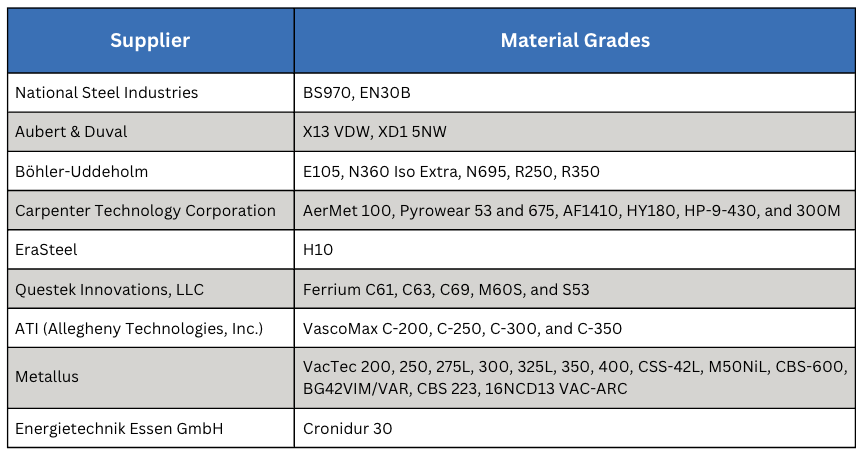
Table A. Advanced Materials Processed by LPC
Vacuum processing can be used for most of the atmosphere treatments mentioned in Part One including carburizing (Figure 1). Low pressure carburizing (LPC) is a proven technology and the choice for many advanced applications in aerospace, automotive, off-highway, and motorsports markets, as well as the development of carburizing cycles for high-performance materials (Table A).
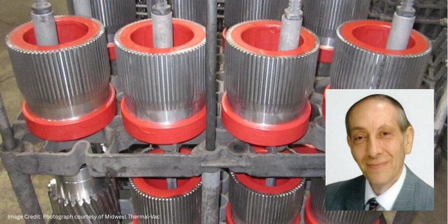
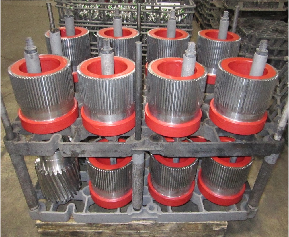
Figure 1. Typical commercial heat treat load of gears for vacuum carburizing (Otto and Herring 2007) | Image Credit: Photo courtesy of Midwest Thermal-VacFigure 2. Pyrowear 675 – LPC – anneal – double normalize – harden – anneal – deep freeze – double temper | Image Credit: The HERRING GROUP, Inc.
The range of effective case depths for most of these grades can range up to 2.0–3.0 mm (0.080–0.120 inches) without significant sacrifice of microstructure (Figure 2). Furnace variables, such as temperature uniformity (± 3°C or ± 5°F), control of cycle parameters (boost/diffuse times, gas flow rate, pressure, hydrocarbon type) and surface carbon optimize the microstructure, producing case uniformities of ± 0.05 mm (± 0.002 inches). Where permitted, the range of carburizing temperatures now includes the use of high temperature (> 980°C, or 1800°F) techniques.
All these advanced materials required extensive development testing to produce custom designed recipes to optimize cycle parameters. Also, quenching methods (Otto and Herring 2002) have improved, allowing us to achieve desired core properties with quenching parameter selection (high-pressure gas or oil) for distortion-sensitive and distortion-prone part geometries (Otto and Herring 2005, 2008).
Induction Hardening Methods
Various methods of hardening via applied energy are used in manufacturing gears, including flame hardening, laser surface hardening, and induction hardening.
Of the various types of applied energy processing, induction hardening is the most common. Induction heating is a process that uses alternating electrical current that induces a magnetic field, causing the surface of the gear teeth to heat. The area is then quenched resulting in an increase in hardness within the heated area. This process is typically accomplished in a relatively short time. The final desired gear performance characteristics are determined not only by the hardness profile and stresses but also by the steel composition and prior microstructure. External spur and helical gears, bevel and worm gears, racks, and sprockets are commonly induction hardened. Typical gear steels include AISI/SAE grades 1050, 1060, 1144, 4140, 4150, 4350, 5150, and 8650.
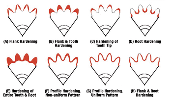
Figure 3. Patterns produced by induction hardening (Rudnev 2000)
The hardness pattern produced by induction heating (Figure 3) is a function of the type and shape of inductor used, as well as the heating method. Quenching or rapidly cooling the workpiece can be accomplished by spray or submerged quench. The media typically used for the quench is a water-based polymer. The severity of this quenchant can be controlled by the polymer’s concentration. Cooling rates are usually somewhere in between what would be obtained from pure water and oil. In some unusual situations compressed air or nitrogen is used to quench the part.
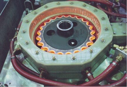
The most common methods for hardening gears and sprockets are by single shot (Figure 4) or the tooth-by-tooth method (Figure 5). Single shot often requires large kW power supplies but results in short heat/quench times and higher production rates. This technique uses a circumferential copper inductor, which will harden the teeth from the tips downward.
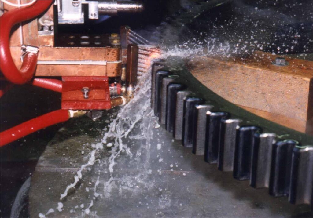
Figure 4. Typical single shot induction hardening operation | Image Credit: Photo courtesy of Ajax-Tocco-MagnethermicFigure 5. Tooth-by-tooth induction hardening of a helical gear | Image Credit: Photo courtesy of Ajax-Tocco-Magnethermic
The larger and heavier loaded gears (where pitting, spalling, tooth fatigue, and endurance are issues) need a hardness pattern that is more profiled like those produced by carburizing, which can be obtained by tooth-by-tooth hardening. This method is limited to gear tooth sizes with modulus 4.23–5.08 (6 or 5 DP) using frequencies from 2 to 10 kHz and about 2.54 (10 DP) using a range of 25 to 50 kHz.
The lower the frequency, the deeper the case depth. Tooth-by-tooth hardening is a slow process and usually reserved for gears and sprockets that are too large to single shot due to power constraints. The process involves heating the root area and side flanks simultaneously, while cooling each side of the adjacent tooth to prevent temper-back on the backside of each tooth. The induction system moves the coil at a pre-programmed rate along the length of the gear. The coil progressively heats the entire length of the gear segment while a quench follower immediately cools the previously heated area. The distance from the coil to the tooth is known as coupling or air gap. Any changes in this distance can yield variation in case depth, hardness, and tooth distortion. The gear is indexed after each tooth has been hardened, often skipping a tooth. This requires at least two full revolutions in the process to complete the hardening of all teeth. Straight, spur, and helical gears up to 5.5 m (210 inches) weighing 6,800 kg (15,000 lb) have been processed with this method. The entire process yields a repeatable soft tip of the tooth with hard root and flank. In other applications, the tip and both flanks can be hardened simultaneously and yield a soft root.
In Summary
Today’s design engineer has the good fortune of being able to choose from a number of heat treatment technologies for any given type of gear material and design. When selecting a gear hardening method, it is essential to specify not only the desired mechanical and metallurgical properties, but the critical dimensions that must be held and even the desired stress state of the gears themselves. The secret to success is understanding the advantages and limitations of each technology and taking these into consideration when determining the overall cost of gear manufacturing.
References
Herring, Daniel H. 2004a. “Gear Heat Treatment: The Influence of Materials and Geometry.” Gear Technology, March/April.
Herring, Daniel H. 2004b. “Reducing Distortion in Heat-Treated Gears.” Gear Solutions, June.
Herring, Daniel H. 2007a. “Oil Quenching Technologies for Gears.” With Steven D. Balme. Gear Solutions, July.
Herring, Daniel H. 2007b. “Heat Treating Heavy Duty Gears.” With Gerald D. Lindell. Gear Solutions, October.
Herring, Daniel H. 2012–2016. Vacuum Heat Treatment. Vols. 1–2. BNP Media Group.
Herring, Daniel H. 2014–2015. Atmosphere Heat Treatment. Vols. 1–2. BNP Media Group.
Herring, Daniel H., Gerald D. Lindell, D. J. Breuer, and B. Matlock. 2001. “Atmosphere vs. Vacuum Carburizing.” Heat Treating Progress, November.
Herring, Daniel H., Gerald D. Lindell, D. J. Breuer, and B. Matlock. 2002. “An Evaluation of Atmosphere and Vacuum Carburizing Methods for the Heat Treatment of Gears.” In Off-Highway Conference Proceedings. SAE International.
Otto, Frederick J., and Daniel H. Herring. 2002a. “Gear Heat Treatment: Today and Tomorrow, Part 1.” Heat Treating Progress, June.
Otto, Frederick J., and Daniel H. Herring. 2002b. “Gear Heat Treatment: Today and Tomorrow, Part 2.” Heat Treating Progress, July/August.
Otto, Frederick J., and Daniel H. Herring. 2005. “Vacuum Carburizing of Aerospace and Automotive Materials.” Heat Treating Progress, January/February.
Otto, Frederick J., and Daniel H. Herring. 2007. “Advancements in Precision Carburizing of Aerospace and Motorsports Materials.” Heat Treating Progress, May/June.
Otto, Frederick J., and Daniel H. Herring. 2008. “Improvements in Dimensional Control of Heat Treated Gears.” Gear Solutions, June.
Rudnev, V. 2000. “Gear Heat Treating by Induction.” Gear Technology, March/April.
About the Author
Dan Herring “The Heat Treat Doctor” The HERRING GROUP, Inc.
Dan Herring has been in the industry for over 50 years and has gained vast experience in fields that include materials science, engineering, metallurgy, new product research, and many other areas. He is the author of six books and over 700 technical articles.
Carbon emissions reporting is no longer optional for heat treaters — it’s becoming a competitive and regulatory necessity. In this Sustainability Insights installment, Heat TreatToday examines research from Professor Fu Zhao and PhD candidate Lakshmi Srinivasan of Purdue University’s Heat Treating Consortium, detailing a new python-based carbon calculator built specifically for heat treat operations, how it models Scope 1, 2, and 3 emissions from furnace geometry and process parameters, and how in-house heat treaters can use it to meet growing transparency demands with minimal manual effort.
This informative piece was first released in Heat Treat Today’sFebruary 2026 Annual Air & Atmosphere Heat Treating print edition.
Emissions reporting has become an essential step. Navigating the requirements in an influx political environment only adds to the challenge. How can heat treaters remain in compliance? A tool designed through Purdue University’s Heat Treating Consortium (PHTC) may be the answer.
The consortium has funded research across heat treat projects ranging from the efficacy of novel quenchants to improving materials hardness. Roughly two years ago, the PHTC member companies requested research to develop a tool that would make carbon estimation possible.
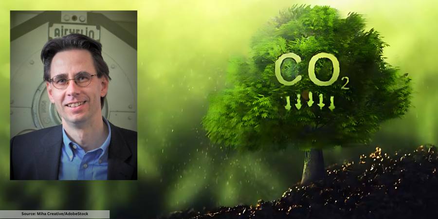
Lakshmi Srinivasan, PhD Candidate in the School of Mechanical Engineering at Purdue UniversityProfessor Fu Zhao, Faculty Member at the School of Mechanical Engineering and the School of Sustainability Engineering and Environmental Engineering at Purdue University
Professor Fu Zhao, faculty member at the School of Mechanical Engineering and the School of Sustainability Engineering and Environmental Engineering at Purdue, decided to take on this research request. He brought on PhD candidate Lakshmi Srinivasan, an astute researcher of energy systems modeling and life cycle assessment in the School of Mechanical Engineering, to research and develop the tool. “This project aims to model furnace energy requirements based on furnace geometry and heat treating input parameters,” Srinivasan explained. “From these modeling energy flows and furnace build inputs, we calculate Scope 1, Scope 2 and Scope 3 carbon emission associated with operating the furnace.”
Scope 1: Direct carbon emissions from energy consumption within the plan (e.g. combustion of natural gas or other fuels)
Scope 2: Indirect emissions from purchased electricity, steam, heat, or cooling
Scope 3: All other indirect emissions across the supply chain (e.g., suppliers, transportation, product use)
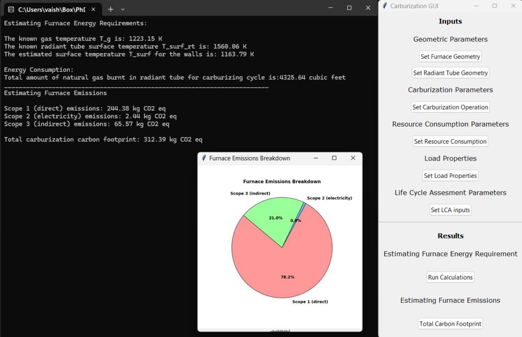
The tool is a python-based desktop application with scalability in mind. Since development targets the carburizing process for both market and regulatory reasons, it is highly focused on industry needs. Additionally, Zhao and Srinivasan built the tool for users to integrate additional features and data sets to align with new requirements or emerging technologies. They also underscored that the tool’s architecture is designed for growth as a web-based application.
Image of the digital carburization tracking tool | Image Credit: Srinivasan and Zhao
Ease of use is central. Zhao and Srinivasan have refined the tool to limit how much unique user input is required to generate an accurate output. The team explained this as particularly challenging, having examined alternatives to simplify the interface without oversimplify the “underlying physics.” They described how the final form of the tool will work, saying that once key parameters are entered (furnace type, processing temperatures, time, part geometry), the tool will automatically calculate energy usage and emissions with minimal manual intervention.
PHTC members, many of whom represent manufacturers with in-house heat treating, have shown great interest, providing feedback and resources to shape the development of the tool. Additional enthusiasm was found at IHEA’s annual SUMMIT in August 2025, where Srinivasan presented the tool’s development. When asked what inquiries have directed their research, Zhao and Srinivasan shared the following:
Versatility and functionality: How flexible is the tool in accommodating different furnace geometries, part geometries, furnace types, and heat treatment processes?
Part-based allocation: How does the tool allocate emissions accurately to individual parts or batches within a furnace load?
Location-specific emissions: How does it account for location-based variations in scope 2 and scope 3 emissions, such as differences in electricity generation or supply chain impacts?
Another challenge has been ensuring careful tool calibration and verification. To do so, the team has taken accurate, real-world natural gas and electricity consumption from heat treat operations, courtesy of PHTC members, to verify the model’s predicted energy consumption at defined furnace operating temperatures.
Eventually, some form of this tool will be made available to those outside the consortium. Currently, however, PHTC members are at the forefront of development and usage. The researchers underlined this, commenting, “This tool is particularly timely and essential for industry, as companies are increasingly expected to provide transparent and accurate emissions reporting.”
While the world of standards and regulations can feel like a minefield, benchmarked discussions of this tool reveal promising applications for in-house heat treaters in the near future.
El reporte de emisiones de carbono ya no es opcional para los especialistas en tratamiento térmico — se está convirtiendo en una necesidad competitiva y regulatoria. En esta entrega de Perspectivas de Sostenibilidad, Heat TreatToday examina la investigación del Profesor Fu Zhao y la candidata a Doctorado Lakshmi Srinivasan del Heat Treating Consortium de Purdue University, detallando una nueva calculadora de carbono basada en Python, desarrollada específicamente para operaciones de tratamiento térmico, cómo modela las emisiones del Alcance 1, 2 y 3 a partir de la geometría del horno y los parámetros del proceso, y cómo los especialistas en tratamiento térmico con operaciones internas pueden utilizarla para cumplir con las crecientes exigencias de transparencia con un mínimo de intervención manual.
Este artículo informativo se publicó por primera vez enHeat Treat Today’sFebruary 2026 Annual Air & Atmosphere Heat Treating print edition.
Si tiene comentarios o preguntas sobre este artículo, háganoslo saber en: editor@heattreattoday.com.
El reporte de emisiones se ha convertido en un paso esencial. Navegar los requisitos en un entorno político cambiante solo añade complejidad al desafío. ¿Cómo pueden los especialistas en Tratamiento Térmico mantenerse en el cumplimiento normativo? Una herramienta diseñada a través de Purdue University’s Heat Treating Consortium (PHTC, por sus siglas en inglés) podría ser la respuesta.
El consorcio ha financiado investigaciones en proyectos de tratamiento térmico que abarcan desde la eficacia de nuevos medios de temple hasta la mejora de dureza de los materiales. Hace aproximadamente dos años, las empresas miembros del PHTC solicitaron una investigación para el desarrollo de una herramienta que hiciera posible la estimación de carbono.
Lakshmi Srinivasan, Candidata a Doctorado en School of Mechanical Engineering at Purdue UniversityProfessor Fu Zhao, Miembro del Profesorado de School of Mechanical Engineering and the School of Sustainability Engineering and Environmental Engineering at Purdue University
El Profesor Fu Zhao, miembro del profesorado de School of Mechanical Engineering and the School of Sustainability Engineering and Environmental Engineering at Purdue decidió asumir esta solicitud de investigación. Incorporando a la candidata a Doctorado Lakshmi Srinivasan, una destacada investigadora en el modelado de sistemas energéticos y evaluación del ciclo de vida en School of Mechanical Engineering y la School of Sustainability Engineering and Environmental, para la investigación y desarrollo de esta herramienta. “Este proyecto tiene como objetivo modelar los requerimientos energéticos del horno en función de su geometría y los parámetros de entrada de tratamiento térmico”, explicó Srinivasan. “A partir de estos flujos energéticos modelados y de los insumos asociados a la construcción del horno, calculamos las emisiones de carbono del Alcance 1, Alcance 2 y Alcance 3 asociados a la operación del horno”.
Alcance 1: Emisiones directas de carbono derivadas del consumo de energía dentro de la planta (por ejemplo, combustión de gas natural u otros combustibles)
Alcance 2: Emisiones indirectas provenientes de electricidad, vapor, calor o enfriamiento adquiridos
Alcance 3: Todas las demás emisiones indirectas a lo largo de la cadena de suministro (por ejemplo, proveedores, transporte, uso del producto)
La herramienta es una aplicación de escritorio basada en Python, diseñada pensando en la escalabilidad. Dado que el desarrollo está orientado al proceso de carburizado tanto por razones de mercado como regulatorias, se encuentra altamente enfocada en las necesidades de la industria. Adicionalmente, Zhao y Srinivasan diseñaron la herramienta para que los usuarios puedan integrar características adicionales y conjuntos de datos que se alineen con nuevos requerimientos o tecnologías emergentes. También subrayaron que la arquitectura de la herramienta está pensada para su crecimiento como una aplicación basada en la web.
Imagen de la herramienta digital de seguimiento de carburizado | Image Credit: Srinivasan and Zhao
La facilidad de uso es un aspecto esencial. Zhao y Srinivasan han refinado la herramienta para limitar la cantidad de entradas únicas requeridas por el usuario para generar un resultado preciso. El equipo explicó que este aspecto fue particularmente desafiante, ya que se examinaron alternativas para simplificar la interfaz sin simplificar en exceso la “física subyacente”. Describieron como funcionará la versión final de la herramienta, explicando que una vez que se introduzcan los parámetros clave (tipo de horno, temperaturas de proceso, tiempo, pieza) la herramienta automáticamente calculará la energía usada y las emisiones con una intervención manual mínima.
Los miembros del PHTC, de los cuales muchos representan compañías manufactureras que cuentan con tratamiento térmico interno, han mostrado interés, proporcionando retroalimentación y recursos para dar forma al desarrollo de la herramienta. Un entusiasmo adicional se observó durante el IHEA’s annual SUMMIT en agosto de 2025, donde Srinivasan presentó el desarrollo de la herramienta. Cuando se les preguntó qué interrogantes han guiado su investigación, Zhao y Srinivasan compartieron lo siguiente:
Versatilidad y funcionalidad: ¿Qué tan flexible es la herramienta para adaptarse a diferentes geometrías de horno, geometrías de piezas, tipos de hornos y procesos de tratamiento térmico?
Asignación basada en piezas: ¿Cómo asigna la herramienta las emisiones de manera precisa a piezas individuales o lotes de una carga dentro del horno?
Emisiones específicas por ubicación: ¿Cómo considera las variaciones regionales en las emisiones del Alcance 2 y Alcance 3, tales como las diferencias en la generación de electricidad o los impactos de la cadena de suministro?
Otro desafío ha sido garantizar la calibración y verificación cuidadosa de la herramienta. Para ello el equipo ha utilizado datos reales y precisos de consumo de gas natural y electricidad provenientes de operaciones de tratamiento térmico, cortesía de los miembros del PHTC, con el fin de verificar el consumo energético predicho por el modelo a temperaturas de operación definidas del horno.
Eventualmente alguna versión de esta herramienta estará disponible para usuarios fuera del consorcio. Sin embargo, actualmente, los miembros del PHTC se encuentran a la vanguardia tanto del desarrollo como del uso. Los investigadores enfatizaron este punto: “Esta herramienta es particularmente oportuna y esencial para la industria, ya que las empresas enfrentan una creciente expectativa de proporcionar reportes de emisiones transparentes y precisos”.
Si bien el mundo de las normas y regulaciones puede sentirse como un campo minado, las discusiones comparativas sobre esta herramienta revelan aplicaciones prometedoras a corto plazo para los especialistas en tratamiento térmico con operaciones internas.
Ask The Heat Treat Doctor® has returned to bring sage advice to Heat Treat Today readers, answer questions about heat treating, brazing, sintering, and other types of thermal treatments, as well as metallurgy, equipment, and process-related issues. In this installment, Dan Herring examines the essential role of heat treatment in gear performance: exploring the key material and design considerations for power transmission gears, the difference between through hardening and case hardening, and the atmosphere heat treatment processes — from carburizing and carbonitriding to nitriding and nitrocarburizing — that determine how well a gear handles load, wear, and fatigue in heavy-duty applications.
This informative piece was first released in Heat Treat Today’sFebruary 2026 Annual Air & Atmosphere Heat Treating print edition.
Have questions or feedback? We’d love to hear from you — reach out to our editorial team at editor@heattreattoday.com.
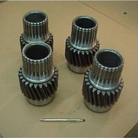
Gears play an essential role in the performance of many products that we rely on in our everyday lives. When we think about gears, we generally separate them into two categories: motion-carrying and power transmission. Motion-carrying gears are generally nonferrous alloys or plastics, while load bearing power transmission gears (Figure 1) are usually manufactured from ferrous alloys and are intended for heavy-duty service applications.
Figure 1. Typical off-highway truck power transmission gears | Image Credit: The Heat Treat Doctor®
Gear Materials & Engineering
Power transmission gears involve a wide variety of steels and cast irons. In all gears, the choice of material must be made only after careful consideration of the performance demanded by the application end-use and total manufactured cost, taking into consideration such issues as pre- and post-machining economics.
Key design considerations require an analysis of the type of applied load, whether gradual or instantaneous, and the desired mechanical properties, such as bending fatigue strength or wear resistance — all of which will define core strength and heat treating requirements.
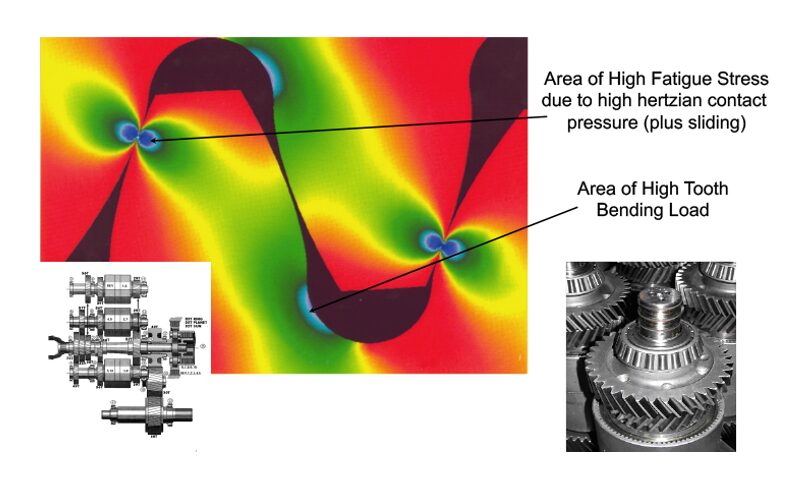
Figure 2. Stress profile in a heavy-duty transmission gear | Image Credit: The Heat Treat Doctor®
It is important for the designer to understand that each area in the gear tooth profile sees different service demands (Figure 2). Consideration must be given to the forces that will act on the gear teeth with tooth bending and contact stress, resistance to scoring and wear, and fatigue issues being paramount. For example, in the root area, good surface hardness and high residual compressive stress are desired to improve endurance or bending fatigue life. At the pitch diameter, a combination of high hardness and adequate subsurface strength are necessary to handle contract stress and wear and to prevent spalling.
Some of the factors that influence fatigue strength are:
Hardness distribution, a function of:
Case hardness
Case depth
Core hardness
Microstructure, a function of:
Retained austenite percentage
Grain size
Carbide size, type, and distribution
Non-martensitic phases
Defect control, a function of:
Residual compressive stress
Surface finish and geometry
Intergranular toughness
In the total manufacturing scheme, a synergistic relationship must exist between the material selection process, engineering design, and manufacturing (including heat treatment). A balance of the priorities in each discipline must be reached to achieve the optimization necessary for the ultimate performance of the gear design. This is often not an easy task.
Various atmosphere heat treatment methods are used for most types of gears including pre-hardening steps (e.g., annealing, normalizing, stress relief) and hardening processes (e.g., neutral hardening and case hardening).
Hardening
Neutral (aka through hardening) refers to heat treatment methods that do not produce a case. Examples of commonly through-hardened gear steels are AISI/SAE grades 1045, 4130, 4140, 4145, 4340, and 8640. It is important to note that hardness uniformity should not be assumed throughout the gear tooth. Since the outside of a gear is cooled faster than the inside, there will be a hardness gradient developed. The final hardness is dependent on the amount of carbon in the steel. The depth of hardness depends on the hardenability of the steel.
Through hardening can be performed either before or after the gear teeth are cut. When gear teeth will be cut after the part has been hardened, machinability becomes an important factor based on final hardness. The hardness is achieved by heating the material into the austenitic range, typically 815°C–875°C (1500°F–1600°F), followed by quenching and tempering.
Case Hardening
By contrast, case hardening is used to produce a hard, wear resistant case (surface layer) on top of a ductile, shock resistant interior (core). The idea behind case hardening is to keep the core of the gear tooth at a level under 40 HRC to avoid tooth breakage while hardening the outer surface to increase pitting resistance.
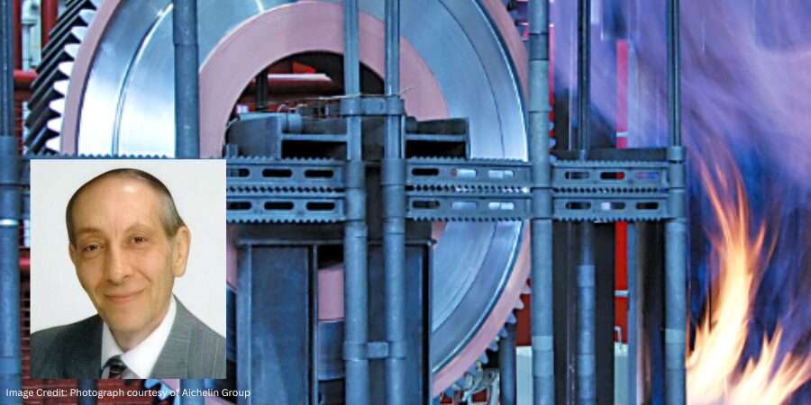
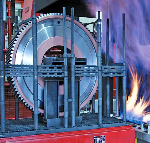
Carburizing
Figure 3. Atmosphere carburizing of large gears | Image Credit: Photograph courtesy of Aichelin Group
Atmosphere carburizing is the most common of the case hardening methods in use today and can handle a diverse range of part sizes and load configurations (Figure 3). In general, a properly carburized gear will be able to handle somewhere between 30–50% more load than a through-hardened gear. Examples of commonly carburized gear steels include AISI/SAE grades 1018, 4320, 5120, 8620, and 9310, as well as international grades, such as 20MnCr5, 17CrNiMo6, 18CrNiMo7-6, and 20MoCr4.
Atmosphere carburizing is typically performed in the temperature range of 870°C–955°C (1600°F–1750°F) although temperatures up to 1010°C (1800°F) are used for deep case work. Carburizing case depths can vary over a broad range, typically 0.13–8.25 mm (0.005–0.325 inches).
Carbonitriding
Carbonitriding is a modification of the carburizing process, not a form of nitriding. This modification consists of introducing ammonia into the carburizing atmosphere to add nitrogen to the carburized case as it is being produced. Examples of gear steels that are commonly carbonitrided include AISI/SAE 1018, 1117, and 12L14.
Carbonitriding is done at a lower temperature than carburizing, typically between 790°C–900°C (1450°F–1650°F), and for a shorter time. Combine this with the fact that nitrogen inhibits the diffusion of carbon, and what generally results is a shallower case than is typical for carburized parts. A carbonitrided case is usually between 0.075–0.75 mm (0.003–0.030 inches) deep.
Nitriding
Nitriding is another surface treatment process that has as its objective increasing surface hardness. One of the appeals of this process is that rapid quenching is not required, hence dimensional changes are kept to a minimum. It is not suitable for all gear applications; one of its limitations is that the extremely high surface hardness case produced has a more brittle nature than say that produced by the carburizing process. Despite this fact, in a number of applications, nitriding has proved to be a viable alternative. Examples of commonly nitrided gear steels include AISI/SAE 4140, 4150, 4340, and Nitralloy® 135M.
Nitriding is typically done in the range of 495°C–565°C (925°F–1050°F). Case depth and case hardness properties vary not only with the duration and type of nitriding being performed but also with steel composition, prior structure, and core hardness. Typically, case depths are between 0.20–0.65 mm (0.008–0.025 inches) and take from 10 to 80 hours to produce.
Nitrocarburizing (Ferritic or Austenitic)
Nitrocarburizing is a modification of nitriding, not a form of carburizing. In the process, nitrogen and carbon are simultaneously introduced into the steel while it is in a ferritic or at times an austenitic condition. A very thin “white” or “compound” layer is formed during the process, as well as an underlying “diffusion” zone. Like nitriding, rapid quenching is not required. Examples of gear steels that are commonly nitrocarburized include AISI/SAE grades 4140, 5160, 8620, and certain tool steels, such as H11 and H13.
Nitrocarburizing is normally performed at 550°C–600°C (1025°F–1110°F) and can be used to produce a 58 HRC minimum hardness, with this value increasing dependent on the base material. White layer depths range from 0.0013–0.056 mm (0.00005–0.0022 inches) with diffusion zones from 0.03–0.80 mm (0.0013–0.032 inches) being typical.
In Summary
There are many ways to heat treat gears. While atmosphere heat treatment (discussed above) is perhaps the most widely used technology today, other types of heat treatments, namely vacuum and induction hardening, are becoming more and more common methods. These will be discussed in Part Two.
About the Author
Dan Herring “The Heat Treat Doctor” The HERRING GROUP, Inc.
Dan Herring has been in the industry for over 50 years and has gained vast experience in fields that include materials science, engineering, metallurgy, new product research, and many other areas. He is the author of six books and over 700 technical articles.
Ask The Heat Treat Doctor® has returned to bring sage advice to Heat Treat Today readers, answer questions about heat treating, brazing, sintering, and other types of thermal treatments, as well as metallurgy, equipment, and process-related issues. In this installment, Dan Herring examines the devastating effects of hot gaseous corrosion on furnace alloys: exploring the mechanisms behind metal dusting, the gas-solid reactions that drive catastrophic carburization, and the mitigation strategies to extend the life of heat treaters’ most valuable furnace components.
This informative piece was first released in Heat Treat Today’sJanuary 2026 Annual Technologies To Watch print edition.
Have questions or feedback? We’d love to hear from you — reach out to our editorial team at editor@heattreattoday.com.
Corrosion is a concern experienced by everyone involved in manufacturing industrial products. While there is a plethora of data and information on the effects of corrosion on engineered materials available (sources provided in the references section of this column), most corrosion engineers are focused on aqueous corrosion. By contrast, heat treaters must understand the effects of hot gaseous corrosion, especially on our furnace alloys. Let’s learn more.
Corrosion Basics
It is important to understand that all materials are chemically unstable in some environments and corrosive attack will always occur. In the scientific world, it can often be modeled and its effects predicted by studying thermodynamic data and knowing which of the many corrosion-related chemical states are active. In our world, however, it is equally important to understand the various forms of corrosion, namely:
Dezincification (aka selective leaching)
Electrolytic
Erosion
Galvanic (or two metal) action
General (aka uniform) attack
Intergranular attack
Pitting
Stress corrosion
The greater the metal’s solubility, the greater the degree and severity of the corrosive attack. There are many important variations of these forms of corrosion; two of the most important are 1) localized corrosive attack (e.g. pits, intergranular attack, crevices) and 2) interaction with mechanical influences (e.g., stress, fatigue, fretting). These actions are frequently rapid and have catastrophic effects.
The number of ways to combat corrosion have been well-documented, including alloying to produce better corrosion resistance materials; cathodic protection (via sacrificial anodes); coatings (metallic or inorganic); organic coatings (e.g. paints); metal purification; alteration of the environment; and nonmetallic or design (i.e., physical) changes.
Heat Resistant Alloys
Furnace interiors contain numerous examples of heat-resistant nickel-chromium-iron (Ni-Cr-Fe) alloys, including radiant tubes, fans, heating elements, roller rails and rollers, thermocouple protection tubes, chain guides, and atmosphere inlet tubes, to name a few. Baskets, grids, and fixtures are other examples. These alloys are normally selected based on their strength (at temperature) rather than resistance to corrosive attack.
Since these heat-resistant alloy parts are often the most expensive furnace components, heat treaters must understand how they can be attacked and what can be done to extend their life by minimizing or preventing corrosion.
Gas-Solid Reactions
A chemical reaction involving a (non-equilibrium) gas or gas mixture and a solid is classified as a gas-solid reaction. Examples of intermediate and high temperature reactions of this type include oxidation, sulfidation, carburization, and nitriding. Effects of gases containing vapors of chlorine, fluorine, and effluents from deposits of various alkaline chemicals (from cleaning compounds) and even phosphates are also problematic. The principles are the same for all types — only the details differ. As heat treaters, our interest is in controlling, retarding, or suppressing these reactions to prevent unwanted corrosion, gasification, or embrittlement of the furnace alloy or materials being processed.
Examples of Catastrophic Carburization (a.k.a. Metal Dusting)
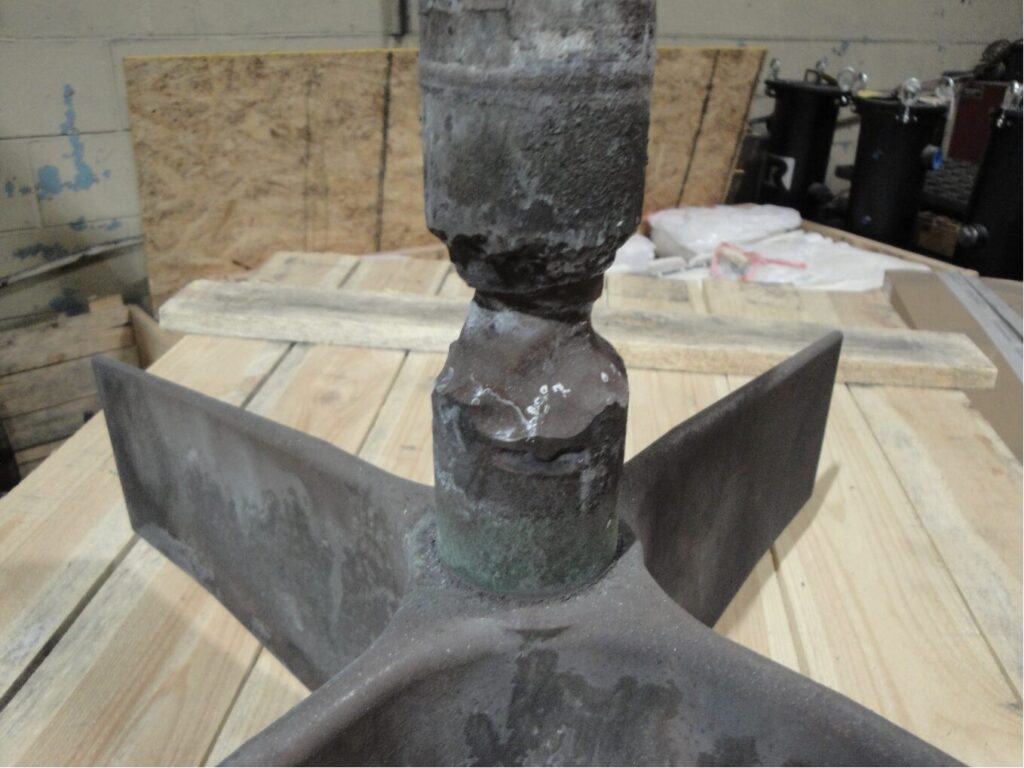
Figure 1. Pusher furnace alloy fan and shaft assembly | Image Credit: The Heat Treat Doctor®
Metal dusting (Figure 1) is a hot gaseous corrosion phenomenon in which a metallic component disintegrates into a dust of fine metal and metal oxide particles mixed with carbon.
Generally, metal dusting occurs in a localized area, and how rapidly the disintegration progresses is a function of temperature, the composition of the atmosphere and its carbon potential, and the material. Other significant factors include the geometry of the system, reaction kinetics, diffusivities of alloy components, the specific-volume ratio of new and old phases, and the ultimate plastic strain.
Metal dusting usually manifests itself as pits or grooves on the surface, or as an overall surface attack in which the metal can literally be eaten away in a matter of days, weeks, or months. As an example, this writer has seen a 330-alloy plate mounted underneath a refractory-lined inner door of an integral quench furnace (where atmosphere passes underneath the door and into the quench vestibule) reduced in thickness from 12.5 mm (0.50 in) to less than 0.75 mm (0.03 in) in a little over two months.
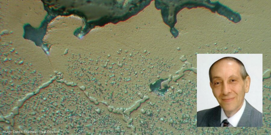
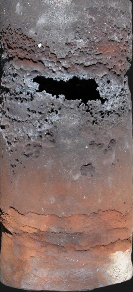
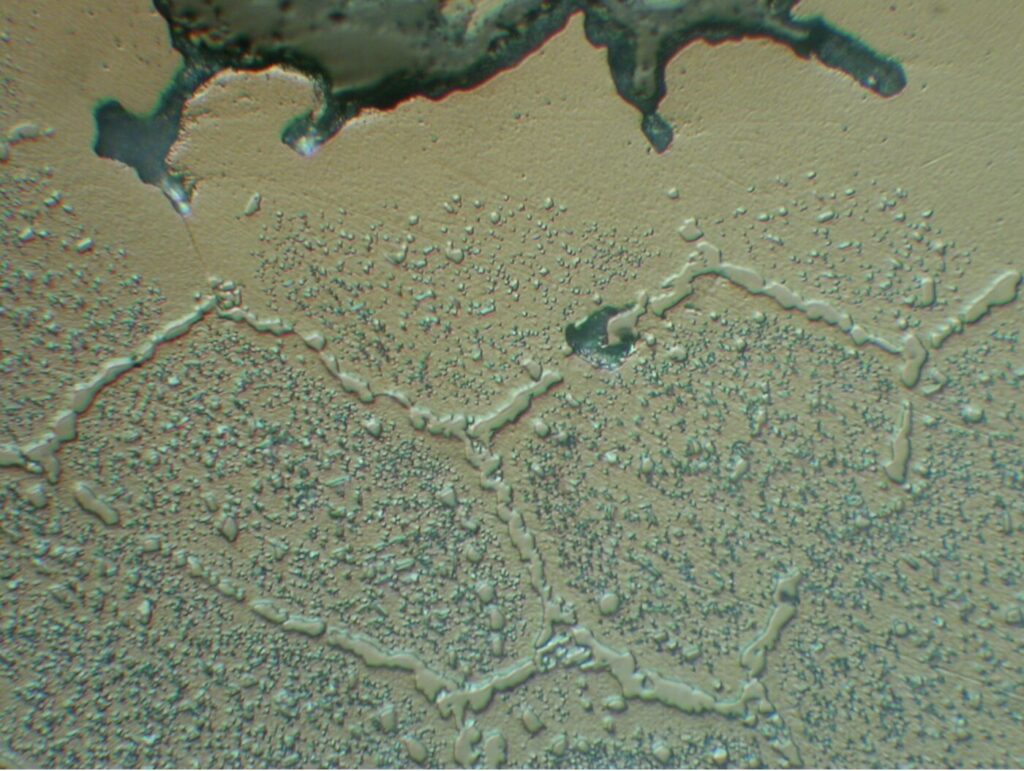
Figure 2. 330 alloy radiant tube removed after six months of use (rotary retort furnace) | Image Credit: The Heat Treat Doctor®Figure 3. Microstructural view: catastrophic carburization | Image Credit: The Heat Treat Doctor®
In another example, a metallographic investigation performed by this writer on a failed wrought 330 alloy radiant tube (Figure 2) was conducted. Optical microscopy of the inside (Figure 3) and outside diameter surfaces in the attacked area revealed evidence of massive carbides. These carbides are formed by the reaction of carbon with chromium, depleting the matrix of chromium in regions adjacent to the carbides. Grain detachment and subsequent failure by erosion then occurred.
How Does It Occur?
In general, catastrophic carburization of ferrous alloys proceeds via the formation and subsequent disintegration of metastable carbide. The first step in the process is absorption of the gaseous phase on the surface of the metal; the more reactive this phase, the easier it decomposes or is catalytically decomposed (in the case of iron) on the surface. This step is followed by diffusion of carbon atoms from the surface into the bulk metal.
As a result, there is a continuous buildup of carbon within the surface layer. As this layer becomes saturated with carbon, a stable carbide, metastable carbide, or an active carbide complex forms, which then grows until it reaches a state of thermodynamic instability, at which point it rapidly breaks down into the metal plus free carbon.
It’s at this stage that the metal disintegrates to a powder as the result of plastic deformation and subsequent fracture in the near-surface layer. The process is controlled by internal stresses due to phase transformation; in other words, competition between stress generation and relaxation exceeds the ultimate strength in this near-surface layer and causes fracture to occur.
In Ni-Cr-Fe alloys, the phenomenon occurs slower (but does not stop) since the disintegration leads to larger metal particles, which are less active catalysts for carbon deposition than the fine iron particles that form with ferrous metals. Therefore, the mass gain from carbon depositing onto high-nickel alloys is much lower. Also, the decomposition of high-nickel alloys occurs by graphitization and not via unstable carbides.
Pourbaix-Ellingham Diagrams
Thermodynamics can be applied to solid-gas reactions to obtain equilibrium dissociation pressures below which no reactions occur. Data and diagrams are available for the free energies of formation versus temperature for most metallic compounds. An interesting use of Pourbaix diagrams (generally reserved for mapping out possible stable equilibrium phases of an aqueous electrochemical system) as a predictor of stable alloy systems is found by superimposing the various elemental constituents. These diagrams are read much like a standard phase diagram (with a different set of axes).
In Summary
Hot gaseous corrosion should be an area of focus for every heat treater to extend the life of alloy components, reduce downtime, and save money. Mitigation in the form of alloy selection, equipment design, type of atmosphere, process/cycle selection, and idling temperatures will play a huge role in extending the life of our furnace alloys, baskets, and fixtures.
References
ASM International. 1971. Oxidation of Metals and Alloys.
Nateson, K. 1980. Corrosion–Erosion Behavior in Metals. Warrendale, PA: Metallurgical Society of AIME.
National Bureau of Standards. 1978. Gas Corrosion of Metals.
Pourbaix, Marcel. 1974. Atlas of Chemical and Electrochemical Equilibria in Aqueous Solutions. Houston, TX: NACE International.
Pourbaix, Marcel. 1998. Atlas of Chemical and Electrochemical Equilibria in the Presence of a Gaseous Phase. Houston, TX: NACE International.
Schweitzer, Philip A. 1996. Corrosion Engineering Handbook. New York: Marcel Dekker.
Staehle, R. W. 1995. “Engineering with Advanced and New Materials.” Materials Science and Engineering A 198 (1–2): 245–56.
Stempco, Michael J. 2011. “The Ellingham Diagram: How to Use It in Heat-Treat-Process Atmosphere Troubleshooting.” Industrial Heating, April.
Uhlig, Hubert H. 2008. Corrosion and Corrosion Control. Hoboken, NJ: Wiley-Interscience.
Fabian, R., ed. 1993. Vacuum Technology: Practical Heat Treating and Brazing. Materials Park, OH: ASM International.
The Boeing Company. n.d. “Practical Vacuum Systems Design Course.”
About the Author
Dan Herring “The Heat Treat Doctor” The HERRING GROUP, Inc.
Dan Herring has been in the industry for over 50 years and has gained vast experience in fields that include materials science, engineering, metallurgy, new product research, and many other areas. He is the author of six books and over 700 technical articles.
Producing durable, wear-resistant gears for the wind turbine industry requires exacting control of carbon diffusion. Modern low pressure carburizing (LPC) is pushing the boundaries of control and consistency. This technology fine tunes carbon diffusion into the surface of components, and applied in a new pit-style vacuum furnace, it also delivers temperature uniformity, stronger gears, and shorter cycle times for large, complex components, all while eliminating oxidation and direct CO₂ emissions. In this Technical Tuesday installment, Tom Hart, director of sales for North America at SECO/WARWICK Corporation, examines how modern LPC technology in a pit-style vacuum furnace is reshaping high-volume carburizing for today’s in-house heat treaters.
This informative piece was first released inHeat Treat Today’sNovember 2025 Annual Vacuum Heat Treating print edition.
The Need To Carburize
Carburizing is a thermochemical treatment that finds applications across the automotive, aviation, and energy industries, particularly in power transmission systems. The widespread use of this process across many industries stems from its ability to improve mechanical properties by enriching the surface of steel with carbon.
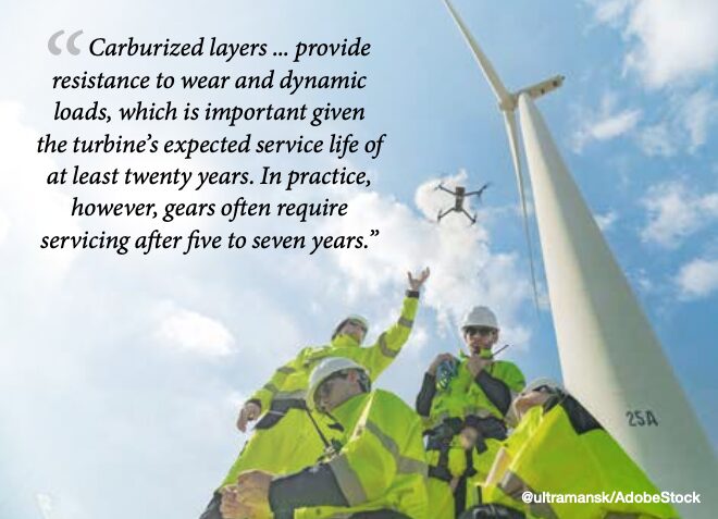
Consider the wind turbine industry, growing with a CAGR (compound annual growth rate) of 6.2% from 2024 to 2033 (GlobeNewswire 2024). Carburizing plays a key role in the production of gears and pinions. These components, often made of alloy steels, such as 18CrNiMo7-6, 4320, 4820, and 9310 (GearSolutions 2009, Jantara 2019), must meet high strength and quality requirements. Carburized layers, often over 4 mm thick, provide resistance to wear and dynamic loads, which is important given the turbine’s expected service life of at least twenty years.
In practice, however, gears often require servicing after five to seven years (Jantara 2019), with their failures generating long downtimes and high costs (Perumal and Rajamani 2014).
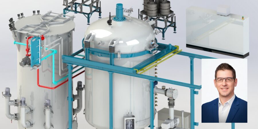
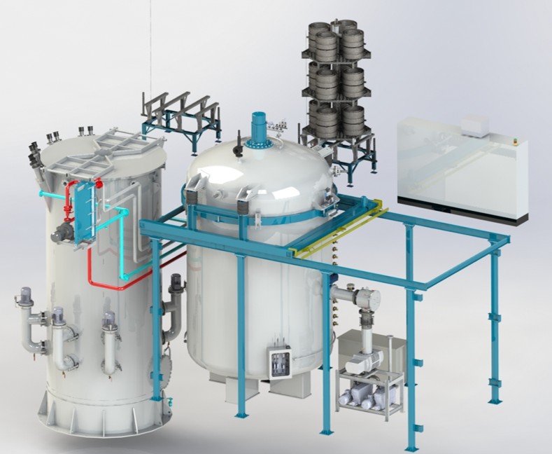
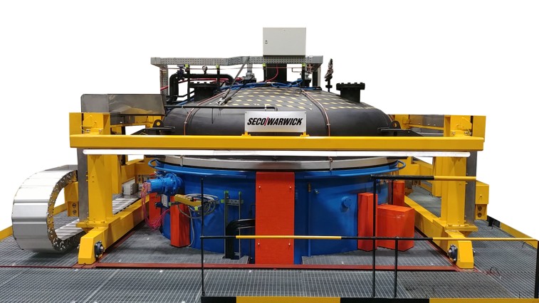
Figure 1a: Pit-LPC in a hardening cell (model)Figure 1b: The view from the operator platform
The carburizing process, combined with hardening (usually in oil) and tempering, increases:
Surface hardness: improving abrasian resistance
Core ductility: protecting against cracks
Fatigue strength: extending the life of the part, which translates into lower operating costs
Alternative technologies, such as nitriding or surface hardening, offer other benefits (e.g., reduced deformation), but have limitations, such as thinner hardened layers, relatively long nitriding process times, or difficulties with complex geometry for surface hardening.
Pit Meets Vacuum LPC
Traditional atmospheric carburizing, despite its established position, has reached its limits in process performance expectations. In response to market needs, LPC (low pressure carburizing) technology is being increasingly implemented to enable precise process control, reduced emissions, and improved energy efficiency. More specifically, a pit furnace with vacuum heat treatment capabilities, aka the Pit-LPC, has been designed and developed to carburize thick layers on very large and/or long parts. This furnace combines the advantages of LPC technology with the ability to integrate existing hardening cells, facilitating the modernization of older installations.
While a vacuum furnace opening to an air atmosphere is a feature previously reserved for atmospheric furnaces, this innovative pit furnace has ceramic insulation and a dedicated heating system to leverage this capability. The chamber door can therefore be opened at process temperature in an air atmosphere for the direct transfer of the charge to the hardening tank. Additionally, the furnace is equipped with a closed circuit forced cooling system, which significantly shortens the charge cooling time from the carburizing temperature to the hardening temperature, increasing efficiency and shortening the production cycle.
Furthermore, the furnace allows for the process to be carried out at temperatures of 1925°F (1050°C) and higher, significantly shortening carburizing time and reducing production costs, even while maintaining a safe level of grain growth (e.g., 1800°F (980°C)).
Benefits of LPC technology designed in a pit furnace include:
Reduced process time due to higher operating temperatures
Elimination of internal oxidation (IGO) in the carburizing process
Highly uniform carburized layer
Low process gas consumption
No direct CO₂ emissions and fire risk
Ready for operation without lengthy conditioning
Computer-aided process support
Additionally, the furnace design increases work safety and comfort in its elimination of open flames, risks of explosion, and the need for constant atmospheric monitoring.
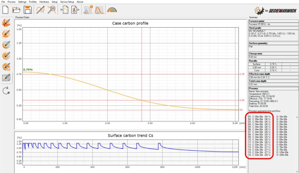
Figure 2. SimVac program window with an example LPC process simulation
This new pit furnace is compatible with SimVac software, developed by Lodz University of Technology and SECO/WARWICK, which enables the simulation and optimization of LPC parameters, reducing the need for process tests. SimVac Plus is a simulation software that includes a vacuum carburizing module (Figure 2). The program can be used either as a standalone tool for designing processes based on the desired carburized layer requirements or to visualize the effect of a given boost/diffusion sequence in the form of a carbon profile.
Testing the Furnace Characteristics and Technical Parameters
The furnace was designed to meet the highest requirements for heat treatment equipment. The basic technical parameters are as follows:
Working space / charge weight: 71″ diameter x 118″ deep / 17,600 lb (1,800 mm x 3,000mm deep / 8,000 kg)
Operating temperature: up to 2010°F (1100°C)
Heating power: 360 kW, three independent zones
Vacuum level: 10⁻² torr
Carburizing gas: acetylene
Temperature Uniformity
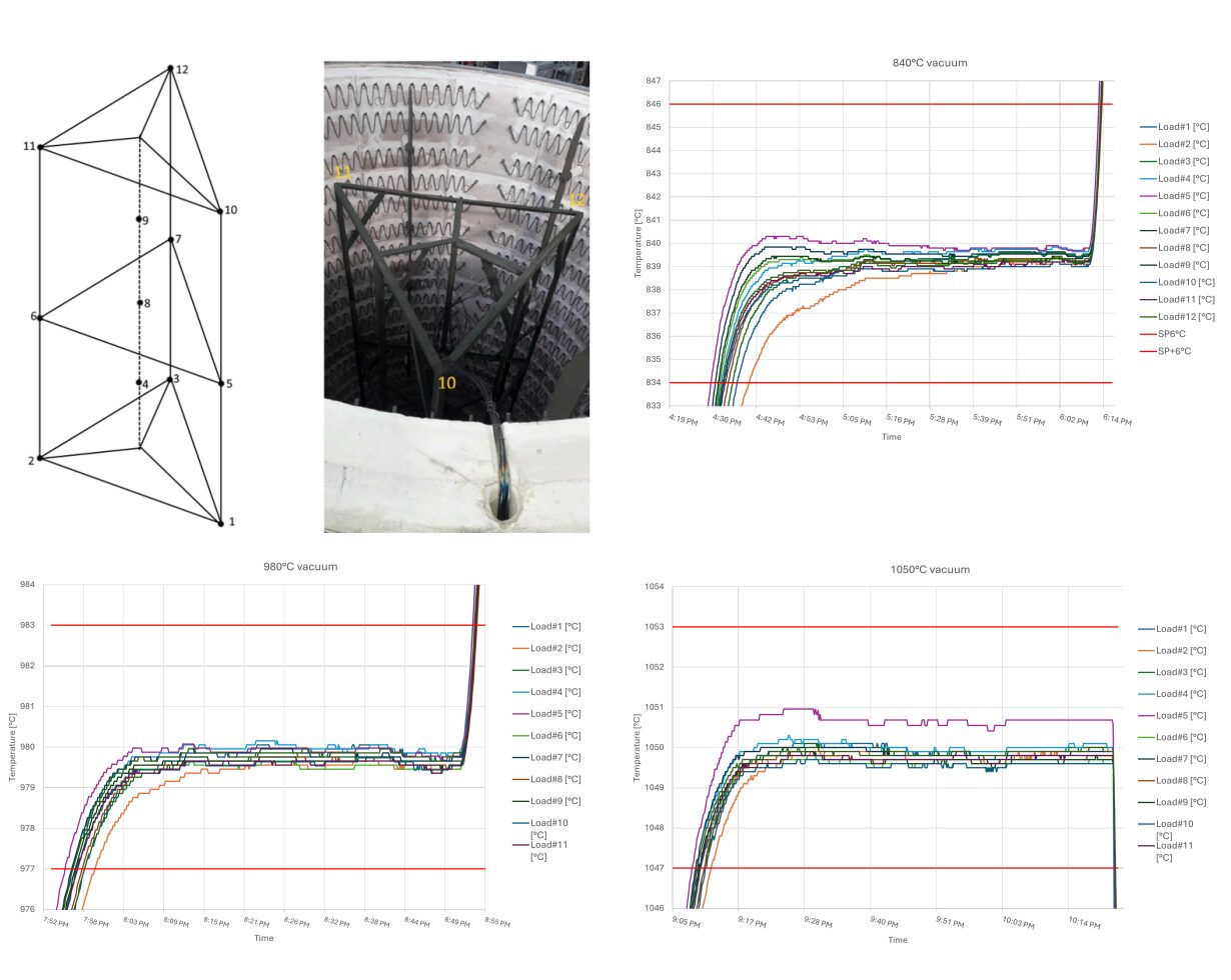
Temperature distribution tests were conducted in the furnace, with 12 load thermocouples arranged according to the diagram shown in Figure 2. Measurements were taken at several temperatures under vacuum conditions. The purpose of the tests was to confirm compliance with the Class 1 ±5°F (3°C) requirements of the AMS2750 standard.
Figures 3a-d. Location of the TUS load thermocouples and the results in vacuum at temperatures of 1550°F (840°C), 1800 °F (980°C), and 1925°F (1050°C)
The results presented in Figure 3 indicate that the furnace provides above-average temperature uniformity, which is particularly important for a large workspace with 71″ diameter x 118″ deep (1,800 mm diameter × 3,000 mm deep) and the processing of large-sized components with thick layers. The temperature difference (ΔT) between the extreme thermocouples, measured at 1550°F (840°C), 1800 °F (980°C), and 1925°F (1050°C), did not exceed 3.5°F (2°C). This means that the furnace meets the Class 1 requirements of the AMS2750 standard by a wide margin.
Operational Dynamics
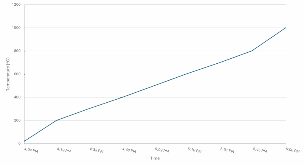
Additionally, to evaluate the furnace’s operational dynamics, heating and cooling tests were performed on an empty device with samples. Figure 4a shows the heating curve; the furnace reaches a temperature of 1800°F (980°C) in 60 minutes. The furnace’s high energy efficiency has a heat loss of just 32 kW under these circumstances.
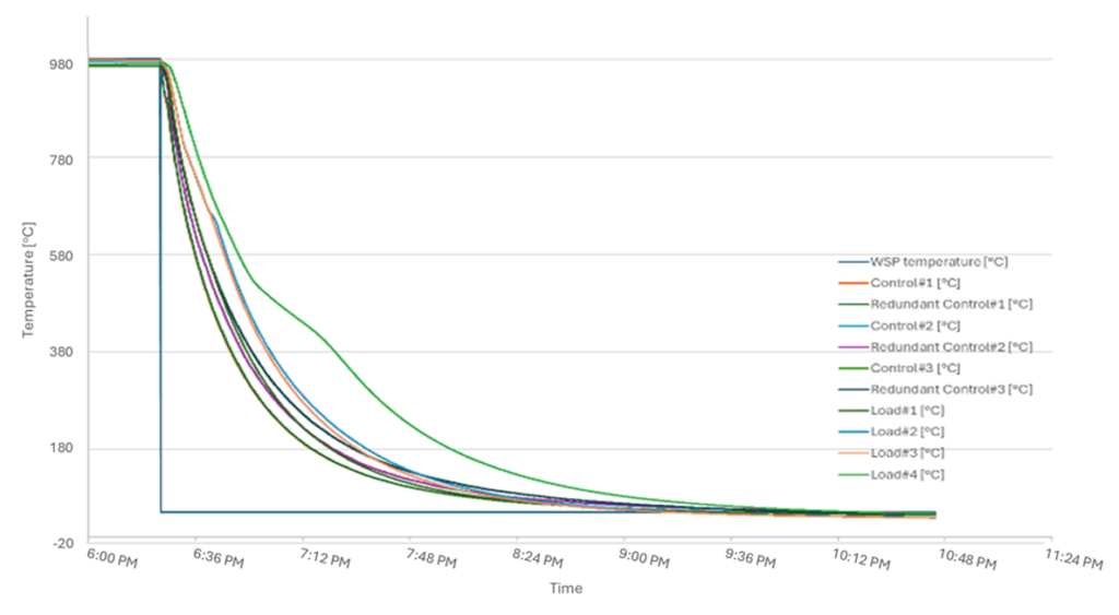
Figure 4a. Heating RateFigure 4b. Cooling Rate
Figure 4b shows teh curve of cooling forced by nitrogen at atmospheric pressure, measured in three zones and on samples with diameters of 1″ (25 mm) and 4″ (100 mm). The temperature drops from 1800°F (980°C) to 575°F (300°C) in 60 minutes; reaching 210°F (100°C) takes only two hours, whereas natural cooling would take several days.
Vacuum tests show that the furnace reaches operating vacuum of 10⁻¹ hPa in under 30 minutes and has a leakage rate of 10⁻³ mbar·l/s, which meets the industry standard for vacuum furnaces.
Test of Atmosphere vs. Vacuum Carburizing Processes
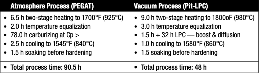
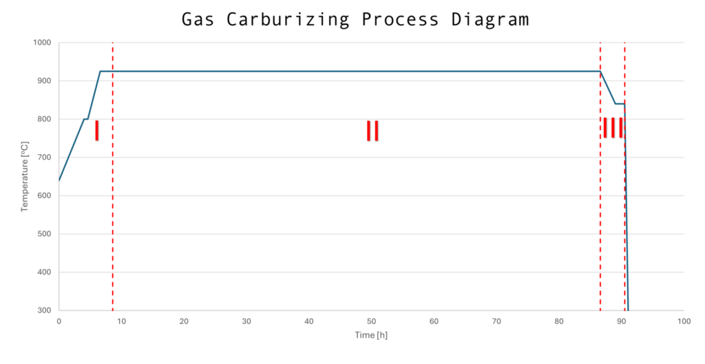
To obtain a carburized layer 0.145–0.160″ (3.7–4.0 mm) thick for 52.3 HRC (550HV1), two tests were compared: one in the PEGAT atmosphere furnace (Figure 5a) and another in the Pit-LPC vacuum furnace (Figure 5b). In both cases, the charge consisted of seven gears made of 18CrNiMo7-6 material, with a total weight of approximately 6.5 tons and a surface area of 280 ft² (26 m²). The process consisted of three stages:
Stage I: heating to the carburizing temperature and soaking
Stage II: actual carburizing with cooling to the hardening temperature and holding
Stage III: hardening in an external quenching tank — identical in both processes
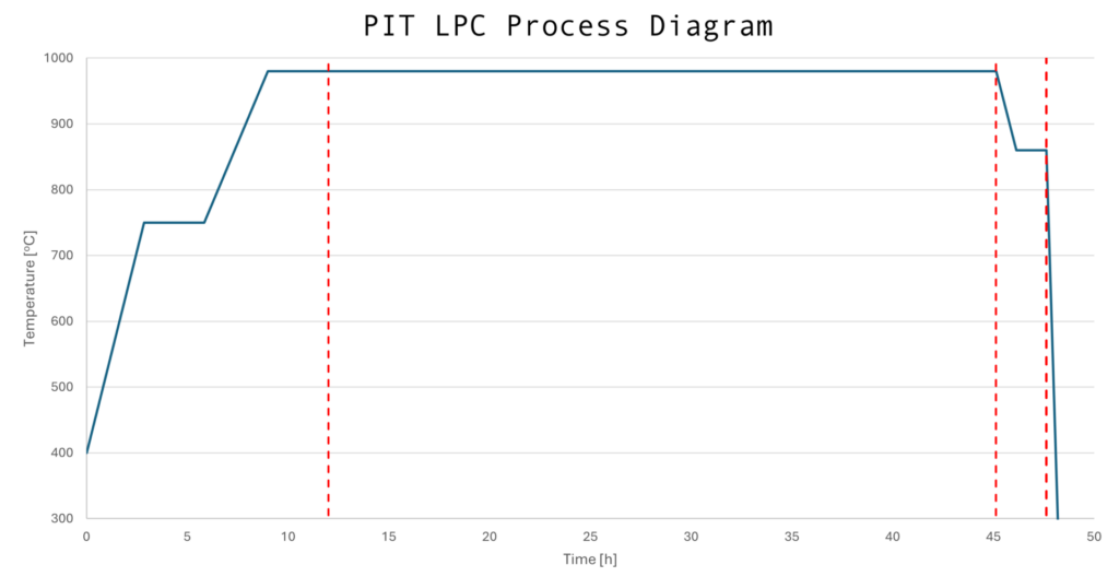
Table A. Atmosphere vs. Vacuum Carburizing Process ComparisonFigure 5a. Essential process data and schematic flow of the carburizing process in a PEGAT atmosphere furnaceFigure 5b. Essential process data and schematic flow of the carburizing process in the Pit-LPC vacuum furnace
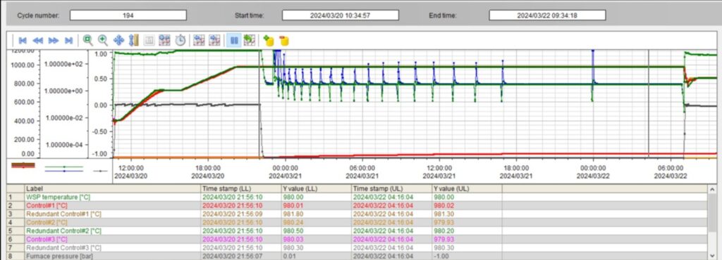
The LPC process, which consists of saturation and diffusion segments (Figure 6) allows for the precise control of carbon distribution. As the process progresses, the duration of the diffusion segments is extended, ensuring uniform saturation of the material.
Figure 6. Vacuum carburizing process trends in the Pit-LPC
After carburizing and hardening, all components were tempered at 355°F (180°C) for three hours.
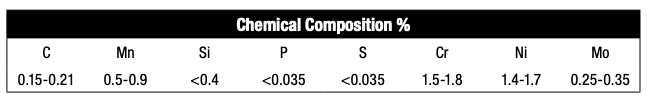
Table B. Chemical Composition of 18CrNiMo7-6 (according to EN10084)
Gears and samples made of 18CrNiMo7-6 steel were used for destructive testing, in accordance with the EN 10084 standard. Six cylindrical samples were placed throughout the workspace — inside and outside the part — to assess carburization uniformity.
Tests conducted:
Vickers microhardness (HV1): performed on a Struers Durascan 70 device, allowing for the determination of hardness profiles and carburized layer depth (ECD) — a load of 9.81 N (HV1).
Surface and core hardness (Rockwell): measurements were performed on a Wilson Wolpert TESTOR tester with a load of 1470.1 N. At least five measurements were taken for each sample.
Microstructure: assessed on a Nikon LV150 optical microscope after nital etching.
Internal oxidation (IGO): analyzed on the unetched surface of the microsection.
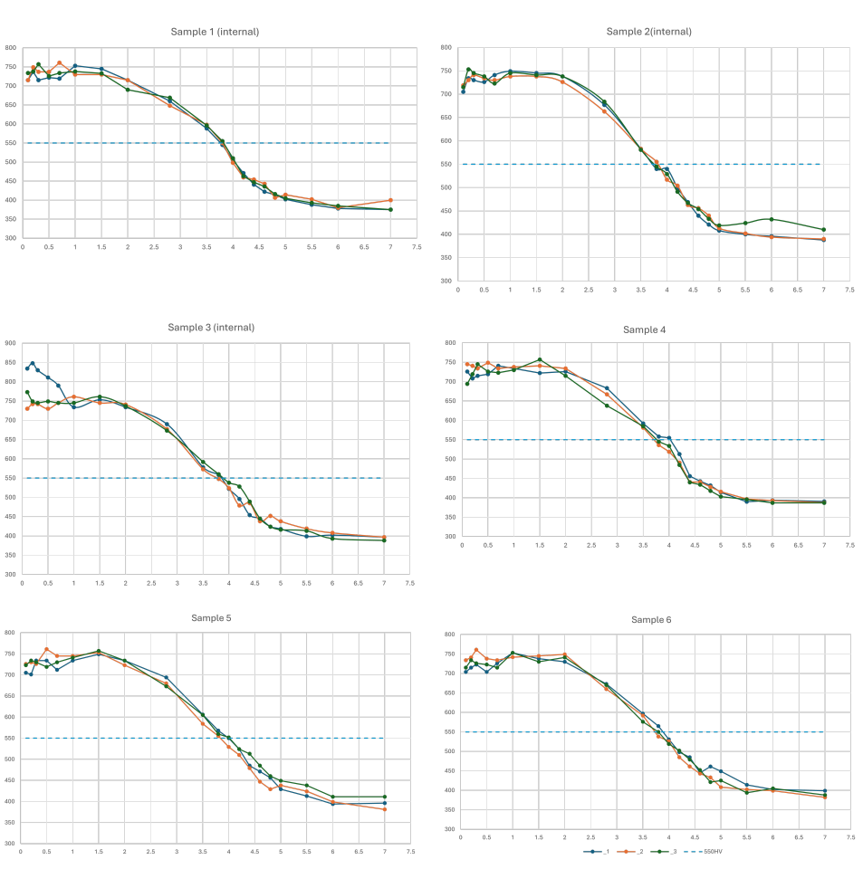
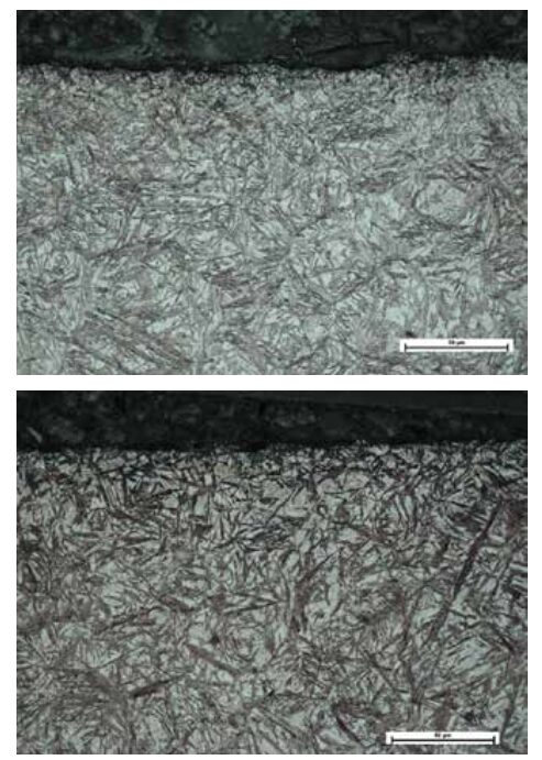
Figures 7a-f. Microhardness profiles after the full process (carburizing, hardening, and tempering)
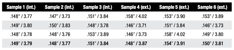
Figure 7 shows the microhardness profiles for the tested samples. For each sample, microhardness paths were inspected in three cross-sections. Based on this, the effective ECD layer thickness obtained on each sample was determined, as presented in Table C.
Table C. Thickness of the Carburized Layer Read from the Microhardness Charts (effective case depth average is 0.145–0.160″ (3.7–4.0 mm) at 52.3 HRC (550 HV1))
Average ECD values obtained for the samples ranged from 0.148 to 0.154″ (3.77 to 3.91 mm).
Surface and core hardness values for all samples were consistent and typical of carburized layers (Table D). Surface hardness ranged from 61.0 to 63.2 HRC and core hardness from 39.9 to 40.7 HRC. Interestingly, samples located on the inner side of the wheel achieved slightly higher surface hardness values (caused by retained austenite and cooling intensity).
Table D. Measured values of surface hardness and core hardness
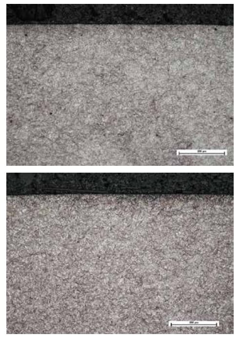
Microstructure images of low-tempered martensite, along with retained austenite, were identified, ranging from 17 to 20% (Figure 8). The amount of retained austenite was determined using NIS-Elements software. No variation in structure was observed depending on sample location.
Figure 8a. Exemplary post-processing microstructure pictures of sample 1 surface. Magnifications x100 (left) and x500 (right). Nital etching 2%. Martensite with residual austenite (approx. 18%).Figure 8b. Exemplary post-processing microstructure pictures of sample 4 surface. Magnifications x100 (left) and x500 (right). Nital etching 2%. Martensite with residual austenite (approx. 20%).
The presence of intergranular oxidation (IGO) was also inspected, averaging 5.5 μm throughout the tested samples. For comparison, intergranular oxidation in the atmospheric process averages above 15 μm. In the new LPC pit furnace, internal oxidation only occurs during unloading and transfer of the charge to the hardening tank, whereas in the atmospheric furnace, the presence of oxygen in the carburizing atmosphere is also significant, significantly increasing the IGO value.
The level of hardening deformation after the process conducted in the new LPC pit furnace and the atmosphere furnace is comparable due to the use of the same hardening tank in both devices and the absence of the carburizing process.
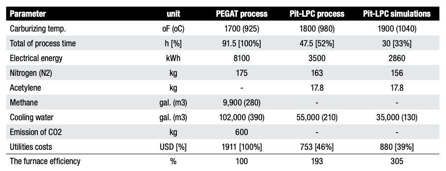
Comparison of Process Economics
Economic aspects play a key role in modern heat and thermochemical processing. Therefore, the consumption of basic utilities was compared for the reference processes (described in Chapter 5), resulting in a 0.152″ (3.8 mm) thick hardened layer. The analysis included a Pit-LPC and a PEGAT-type atmospheric furnace, both with identical workspace and the same charge. In addition, the LPC process was simulated at 1900°F (1040°C). The results are summarized in Table E.
Table E. Comparison of utility consumption and costs
The results show that the new LPC furnace model consumes significantly less electricity by approximately 57%, which translates into a lower carbon footprint, especially when energy is derived from fossil fuels. Nitrogen consumption is comparable, with a slight advantage for the Pit-LPC (savings of up to 10%).
The largest differences are found in carburizing gases. The atmospheric furnace consumes 9,900 ft³ (280 m³) of methane — approximately 440 lb (200 kg) and an additional 4.4–13.2 lb (2–6 kg) of propane per process. In the LPC furnace, acetylene consumption is reduced to 39.2 lb (17.8 kg) because carburizing gas only flows during the boost phase.
Importantly, the LPC process does not generate direct CO₂ emissions, unlike an atmospheric furnace, which emits approximately 1325 lb (600 kg) of CO₂ per cycle. Cooling water consumption in the new LPC furnace is also reduced by over 45%.
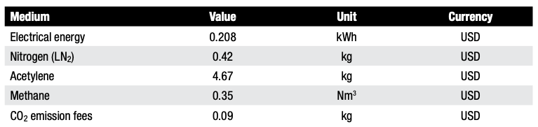
The presented comparison of utility consumption in the two types of furnaces directly translates into the economic aspects of using these devices and conducting production processes. For cost comparison purposes, the following unit utility costs were assumed, as presented in Table F:
Table F. Unit costs of energy factors and technological gases according to European averages
In summary, the total utility costs for the process conducted in the Pit-LPC at 1800°F (980°C) are 53% lower compared to an atmospheric furnace conducted at 1700°F (925°C). At a temperature of 1925°F (1040°C), savings reach 60%. These savings are primarily due to lower energy and process gas consumption. Furthermore, the lack of CO₂ emissions eliminates the need to pay emission fees.
The efficiency of this furnace is almost twice as much at 1795°F (980°C) and three times as much at 1925°F (1040°C) compared to an atmospheric furnace.
Summary
The new Pit-LPC vacuum furnace combines the design features of a top-loaded pit and performs carburizing using vacuum technology instead of atmospheric technology. Bringing higher processing temperatures than traditional atmospheric furnaces to the market, as well as the ability to open hot in an air atmosphere, this technology proves that direct transfer of the charge to the hardening tank is possible in vacuum furnaces.
Another key development, this design significantly shortens carburizing time compared to atmosphere furnaces since the furnace can operate under vacuum, inert gas (nitrogen, argon), air, and carburizing gases, at temperatures up to 2010°F (1100°C).
Since this new pit furnace design does not require the use a retort or atmosphere mixer, which are the most vulnerable components inside a traditional atmospheric furnace, the furnace operates with greater reliability and lower costs. Furthermore, an efficient and robust vacuum pumping system provides the vacuum environment and operational readiness in less than 30 minutes. Time is also saved by the integrated closed-loop gas cooling system that shortens cooling time: dropping temperatures from 1800°F (980°C) to 1545°F (840°C) in 30 minutes for a full charge and to 210°F (100°C) in two hours for an empty furnace, operations which would take several hours and days respectively in atmosphere furnaces.
The advanced thermal insulation and a uniform heating element layout ensure high energy efficiency and precise temperature uniformity in the working space, yielding additional cost and energy savings.
This carburizing process is based on FineCarb LPC technology and supported by the SimVac simulator, enabling precise carbon profile shaping and achieving layers 0.148–0.154″ (3.77–3.91 mm) thick with high repeatability.
With the ability to operate at temperatures up to 1925°F (1050°C), the new LPC pit-styled furnace significantly shortens process time, reduces utility consumption, and lowers operating costs by up to 50%, while increasing productivity by a factor of x2 to x3. One of these furnaces can replace two to three atmosphere furnaces of the same size.
Finally, the furnace operates in a safe and non-flammable atmosphere, emits no direct CO₂, and reduces energy consumption, making it an environmentally friendly solution.
Conclusions
The Pit-LPC furnace is a modern alternative to the traditional atmosphere furnace and offers a number of advantages in terms of quality, efficiency, safety, economy, and ecology. Providing an innovative solution for vacuum carburizing and meeting stringent carburization layer thickness guidelines, this design is a viable option to fully replace traditional atmospheric pit furnaces operating in a carburizing atmosphere.
Jantara, Valter Luiz Jr. 2019. “Wind Turbine Gearboxes: Failures, Surface Treatments and Condition Monitoring.” In Non-Destructive Testing and Condition Monitoring Techniques for Renewable Energy Industrial Assets, edited by Mayorkinos Papaelias, Fausto Pedro García Márquez, and Alexander Karyotakis. Amsterdam: Elsevier.
Perumal, S., and G. P. Rajamani. 2014. “Improving the Hardness of a Wind Turbine Gear Surface by Nitriding Process.” Applied Mechanics and Materials 591: 19–22.
Tom Hart Director of Sales for North America SECO/WARWICK Corporation
Tom Hart joined SECO/WARWICK in 2011 as a sales engineer and has been in the precision manufacturing industry for over 16 years. His responsibilities have him caring for SECO/WARWICK’s clients and their various process and heat treatment equipment needs. Tom received his manufacturing engineering degree from Edinboro University of Pennsylvania, has authored numerous white papers, and is recognized throughout the heat treatment industry as a go-to-guy for thermal processing.
What are the ways to improve the cleaning process of component parts and reduce smoke from residue and environmental impact? Mercury Marine faced this challenge head on with a new system. Learn more about their solution in today’s Technical Tuesday case study written by Chris Tivnan the sales manager for North America at SAFECHEM North America Inc.
This informative piece was first released inHeat Treat Today’sAugust’s 2025 Annual Automotive Heat Treating print edition.
Mercury Marine’s Need for Clean
Mercury Marine is a world leading manufacturer of marine propulsion systems headquartered in Fond du Lac, Wisconsin. A subsidiary of Brunswick Corporation, Mercury Marine designs, manufactures, and distributes engines, services, and parts for recreational, commercial, and government marine applications.
Mercury Marine has an in-house heat treatment facility for the components they manufacture. These components include gear case parts, such as propeller shafts, pinions, forward and reserve gears, and clutches. The parts undergo typical manufacturing steps like turning, milling, or gear tooth generation. Some machines allow for dry cutting, while others involve hydraulic oil. In total, more than 170 distinct metal parts require cleaning before undergoing vacuum carburizing, hardening, tempering, and/or cryogenic treatments.
Carburizing with Closed-Vacuum Solvent Cleaning
But vacuum carburizing has not always been the technology of choice for Mercury Maine. Prior to 2023, parts and components underwent initial cleaning in an aqueous washer before proceeding to atmospheric carburizing. Then, they were quenched in oil and then underwent another round of cleaning with a water-based cleaner.
Figure 1. NANO vacuum carburizing system from ECM
Mercury Marine made the strategic decision to transition from atmospheric carburizing to vacuum carburizing in 2023. The shift was motivated by concerns related to smoke and environmental impact, particularly the evaporation of oil residuals during tempering. The desire for an overall environmentally friendlier process further fueled this change.
Vacuum carburizing benefits from more stringent cleanliness requirements on parts whereby all residue oils, greases, and debris must be removed entirely to prevent contamination of the furnace and the vacuum pump system. As a result of these considerations, Mercury Marine replaced their existing aqueous cleaning process with solvent-based cleaning, convinced that this solution provided superior and consistently reliable cleaning results.
Figure 4. With lipophilic and hydrophilic properties, DOWCLENE™* 1601 removes oils and greases just as effectively as certain polar contaminants like cooling emulsions or solids (e.g., particles and abrasives). Source: ECM USA
Their furnace equipment manufacturer ECM recommended a closed-vacuum solvent-based cleaning machine (Model: SOLVACS 3S) from the manufacturer HEMO. This design could be seamlessly integrated into their NANO vacuum carburizing system.
The vacuum cleaning machine runs on the modified alcohol solvent DOWCLENE™* 1601. Because of its lipophilic and hydrophilic properties, DOWCLENE 1601 can remove oils and greases just as effectively as certain polar contaminants like cooling emulsions or solids (e.g., particles and abrasives). The solvent also has low toxicity and good biodegradability.
Enabling High Environmental and Safety Standards
The switch from aqueous to solvent cleaning initially raised some safety concerns within Mercury Marine’s environmental safety committee. However, these concerns were swiftly addressed once the committee understood the operation of a closed vacuum cleaning machine and how it contributes to the highest safety and sustainability standards.
First, the airtight design of the machine virtually eliminates air emissions. The hermetically sealed construction means there is minimal risk of contaminating groundwater. Additionally, full machine automation removes operator handling and minimizes chemical contact.
Figure 2. While closed vacuum cleaning machines enable high-quality cleaning results with strong safety and sustainability standards, HEMO designs integrate seamlessly into furnace lines
Second, the machine’s built-in distillation unit enables continuous solvent recovery — as high as 95% in Mercury Marine’s case — thereby significantly reducing chemical consumption and waste while lowering overall cleaning costs. Distillation ensures that parts are consistently cleaned in fresh solvent. The effective cleaning result is further warranted by the high solvent quality in the rinsing step, followed by vapor degreasing as the last cleaning step, which is highly effective due to high temperature difference between parts and vapor. With the drying process below 0.1 psi, a perfect drying of the parts is guaranteed.
Additionally, unlike aqueous cleaning, solvent cleaning does not consume significant water, nor does it require wastewater treatment, providing a considerable cost and environmental advantage.
Using a simple test kit, solvent conditions can be easily monitored on a regular basis. Solvent lifespan can also be extended by adding stabilizers, reducing the need for frequent bath exchanges. Due to the high stability of the cleaner, only minimal stabilizer additions have been required since the machine was first put into operation.
Leveraging CFC for Solvent Cleaning
Another crucial factor supporting solvent cleaning is the use of carbon fiber composite (CFC) workload trays and fixturing of the heat treat batch in the cleaning machine. After cleaning the parts, the CFC fixtures are directly transferred into the vacuum furnace. This streamlined workflow eliminates the need to transfer parts between different fixtures, minimizing part damage or contamination while saving time. The durability and thermal stability of CFC fixtures make them ideal for such demanding applications.
Figure 3. Industrial robots streamline the loading and unloading of components in ECM’s vacuum furnaces and facilitate part transfers between systems, ensuring a fully automated heat treatment line
Since CFC is a highly absorbent material, it can soak up liquids during the cleaning process. Any remaining residue in CFC fixtures can be released during a vacuum heat treatment process, contaminating the oven, which will impact the process and cause improper heat treatment outcomes. Unlike aqueous cleaning, which leaves some liquids behind, solvent cleaning under vacuum conditions effectively removes these absorbed residues.
Additionally, CFC fixtures must be properly dried and moisture-free before entering the vacuum furnace. Moisture can lead to contamination, inefficient carburizing, oxidation, or vacuum system problems. Solvents dry much faster than water, mitigating the risk of water vapor migration into the vacuum carburizing system.
Superior Controllability and Quality Results
Since transitioning from atmospheric to vacuum carburizing, Mercury Marine has experienced many benefits due to a significantly more consistent and repeatable heat treatment process.
It is known that residual oxygen within the furnace atmosphere can react with alloying elements on the component’s surface. This interaction can lead to the formation of an oxidation layer, potentially affecting the compressive stress profile. Such layers need to be ground off. However, with vacuum carburization, these intergranular oxidations (IGO) no longer occur.
The vacuum carburizing process follows a precise “boost and diffuse” cycle, where the presence of carbon is transferred via acetylene. This approach provides superior controllability compared to atmospheric carburizing, where natural gas is used. Additionally, the absence of open flames and the energy-efficient design contribute to reduced greenhouse gas emissions.
In the past, Mercury Marine faced cleaning challenges following oil quenching. While maintaining clean quench oil is essential, frequent oil changes can be costly. When the quench oil was not cleaned frequently enough, deposits adhered to parts, especially drive shafts with spiral oil grooves for passage. Despite attempts at aqueous cleaning, such debris could persist, and additional blasting was needed to remove them.
Vacuum carburizing has eliminated this problem as the parts now undergo gas quenching instead of oil quenching, removing the aqueous cleaning step altogether.
The investment in a new furnace system, along with the integrated closed vacuum solvent cleaning machine, has proven highly beneficial. The fully automated system ensures that technicians are not manually handling baskets, while parts are cleaned to the highest standard, enabling a seamless vacuum carburizing process. Mercury Marine has expressed great satisfaction with the results, recognizing the system as a valuable addition to their manufacturing operations.
About The Author:
Chris Tivnan Sales Manager North America SAFECHEM North America Inc.
With two decades of experience in the chemical industry, Chris assists manufacturers in determining the right choice of cleaning agent and their parts cleaning operation. He also manages relationships with regional distributors as well as local OEMs/OEAs.
Given changing ecological and economic conditions, carbon neutrality is becoming more important, and the heat treatment shop is no exception. In the context of this article, the focus will be on how manufacturers — especially those with in-house heat treat — can save energy by evaluating heating systems, waste heat recovery, and the process gas aspects of the technology.
This article, written by Dr. Klaus Buchner, head of Research and Development at AICHELIN HOLDING GmbH, was released in Heat Treat Today April/May 2024 Sustainable Heat TreatTechnologiesprint edition.
Introduction
Contact us with your Reader Feedback!
Uncertainties in energy supply and rising energy costs remind us of our dependence on fossil fuels. This underlines the need for a sustainable energy and climate policy, which is the central challenge of our time.
European policymakers have already taken the first steps towards a green energy revolution, and the heat treatment industry must also take responsibility. Many complementary measures, however, are needed that can be applied to new and existing thermal and thermochemical heat treatment lines.
Heat Treatment Processes and Plant Concepts
The heat treatment process itself is based on the requirements of the component parts, and especially on the steel grade used. If different concepts are technically comparable, it is primarily the economic aspect that is decisive, and not the carbon footprint — at least until now. Advances in materials technology and rising energy costs are calling for production processes to be modified.
Figure 1. Donut-shaped rotary-hearth furnace for carburizing with press quenching Source: AICHELIN HOLDING GmbH
An example is the quenching and tempering of automotive forgings directly from the forging temperature without reheating, which has shown significant potential for energy and CO2 savings. Although the reduced toughness or measured impact energy of quenching and tempering from the forging temperature may be a drawback due to the coarser austenite grain size, this can be partially improved by Nb micro-alloyed steels and higher molybdenum (Mo) contents for more temper-resistant steels; it may also be necessary to use steels with modified alloying concepts when changing the process.1, 2 AFP steels (precipitation-hardening ferritic pearlitic steels) and bainitic air-hardening steels can also be interesting alternatives, since reheating (an energy-intensive intermediate step) is no longer necessary.
Similar considerations apply to direct hardening instead of single hardening in combination with carburizing processes because of the elimination of re-austenitizing. Distortion-sensitive parts often need to be quenched in fixtures due to the dimensional and shape changes caused by heat treatment. Heat treated parts are often carburized in multipurpose chamber furnaces or small continuous furnaces, cooled under inert gas, reheated in a rotary-hearth furnace, and quenched in a hardening press. In contrast, ring-shaped (aka donut-shaped) rotary-hearth furnaces allow carburizing and subsequent direct quenching in the quench press in a single treatment step. Figure 1 shows a typical ring-shaped rotary-hearth furnace concept for heat treating 500,000 gears per year/core hardness depth (CHD) group 1 mm.
Table 1. Saving potential due to increased process temperature for gas carburizing (pusher type furnace, 20MnCr5, CHD-group 1 mm) Source: AICHELIN HOLDING GmbH
This ring-shaped rotary-hearth concept can save up to 25% of CO2 emissions, compared to an integral quench furnace line (consisting of four single-chamber furnaces, one rotary hearth furnace with quench press and two tempering furnaces as well as two Endothermic gas generators). Due to the reduced total process time (without reheating) and the optimized manpower, the total heat treatment costs can be reduced by 20–25%.
The high-temperature carburizing aspect should also be mentioned, although the term “high-temperature carburizing” is not fully accepted nor defined by international standards. As the temperature increases, the diffusion rate increases and the process time decreases. As shown in Table 1, the additional energy consumption is less than the increase in throughput that can be achieved. Therefore, the relative energy consumption per kg of material to be heat treated decreases as the process temperature increases.
There are three key issues to consider when running a high-temperature carburizing process:
Steel grade: Fine-grain stabilized steels are required for direct hardening at temperatures of 1832°F (1000°C). Microalloying of Nb, Ti, and N as well as a favorable microstructure of the steels reduce the growth of austenite grains and allow carburizing temperatures up to 1922°F (1050°C) for several hours.
Furnace design: In addition to the general aspects of the optimized furnace technology (e.g. heating capacity, insulation materials, and feedthroughs), failure-critical components must be considered separately in terms of wear and tear, whereby condition monitoring tools can support maintenance in this area.
Distortion: This is always a concern, especially in the case of upright loading of thin-walled gear sections. As such, numerical simulations and/or experimental testing should be performed at the beginning to estimate possible changes in distortion and to take measures if necessary.
Figure 2. Recuperative burner with SCR system for NOx reduction
Source: AICHELIN HOLDING GmbH
Heating System
Based on an energy balance that considers total energy losses, and preferably also temperature levels, it can be seen that the heating system plays a significant role. In addition to the obvious flue gas loss in the case of a gas-fired thermal processing furnace, the actual carbon footprint must be critically examined.
In the case of natural gas, the upstream process chain is often neglected in terms of CO2 emissions, but the differences in gas processing (which are directly linked to the reservoirs) and in gas transportation can be a significant factor.3 However, the analysis of energy resources in the case of electric heating systems is much more important. This results in specific CO2 emissions between 30–60 gCO2/kWh (renewable-based electricity mix) and 500–700 gCO2/kWh (coal-based electricity mix). Therefore, a general comparison between natural gas heating and electric heating systems in terms of carbon footprint is often misleading.
Figure 3. Comparison of specific CO2 emissions
Source: AICHELIN HOLDING GmbH
Nevertheless, in the case of gas heating, the aspect of combustion air preheating should be emphasized, as it has a significant influence on combustion efficiency. The technical possibilities in this area are well known and include both systems with central air preheating and decentralized concepts, where the individual burner and the heat exchanger form a single unit. Recuperator burners are often used in combination with radiant heating tubes (indirect heating) in the field of thermochemical heat treatment. With respect to oxy-fuel burners, it should also be noted that the formation of thermal NOx increases with increasing combustion temperature and temperature peaks. To avoid exceeding NOx emissions, staged combustion and so-called “flameless combustion” — characterized by special internal recirculation — and selective catalytic reduction (SCR) can be used. The latter secondary measure, together with selective non-catalytic reduction (SNCR), has been state-of-the-art in power plant design for decades and has become widely known because of its use in the automotive sector. This system can also be adapted to single burners (Figure 2). In this way, NOx emissions can be reduced to 30 mg/Nm3 (5% reference oxygen), depending on the injection of aqueous urea solution, as long as the exhaust gas temperature is in the range of 392/482°F (200/250°C) to 752/842°F (400/450°C).4
Whether electric heating is a viable alternative depends on both the local electricity mix and the design of the heat treatment plant, which may limit the space available for the required heating capacity. In addition to these technical aspects, the security of supply and the energy cost trends must also be considered. Both of these factors are significantly influenced by the political environment. Figure 3 shows an example of the specific carbon footprint per kg of heat treated material with the significant losses based on the example of an integral quench furnace concept in the double-chamber and single-chamber variants electrically heated (E) and gas heated (G). The electric heating is based on a fossil fuel mix of 485 gCO2/kWh. Once again, it is clear that a general statement regarding CO2 emissions is not possible; rather, the boundary conditions must be critically examined.
Waste Heat Recovery — Strengths and Weaknesses of the System
Although improvements in the energy efficiency of heat treatment processes, equipment designs, and components are the basis for rational energy use, from an environmental perspective it is important to consider the total carbon footprint. An energy flow analysis of the heat treatment plant, including all auxiliary equipment, shows the total energy consumption and thus the potential savings. Quite often the temperature levels and time dependencies involved preclude direct heat recovery within the furnace system at an economically justifiable investment cost. In this case, cross-plant solutions should be sought, which require interdepartmental action but offer bigger potential.
In addition to the classic methods of direct waste heat utilization using heat exchangers, also in combination with heat accumulators, indirect heat utilization can lower or raise the temperature level of the waste heat by using additional energy (chiller or heat pump) or convert the waste heat into electricity. The overview in Table 2 provides reference values in terms of performance class and temperature level for the alternative technologies listed.
Process Gas for Case Hardening
Case hardening — a thermochemical process consisting of carburizing and subsequent hardening — gives workpieces different microstructures across the cross-section, the key factor being high hardness/strength in the edge region. A distinction can be made between low pressure carburizing in vacuum systems and atmospheric carburizing at normal pressure. Both processes have different advantages and disadvantages, with atmospheric heat treatment being the dominant process.
Table 2. Overview of alternative waste heat applications5, 6 Source: AICHELIN HOLDING GmbH
In terms of carbon footprint, atmospheric heat treatment has a weakness due to process gas consumption. To counteract this, the following aspects have to be considered: thermal utilization of the process gas — indirectly by means of heat exchangers or directly by lean gas combustion (downcycling); reprocessing of the process gas (recycling); reduction of the process gas consumption by optimized process control; and use of CO2-neutral media (avoidance). This article focuses on avoidance by optimizing process gas consumption and using of CO2-neutral media.
Typically, heat treatment operations are still run with constant process gas quantities based on the most unfavorable conditions. Based on the studies of Wyss, however, process control systems offer the possibility to adapt the actual process gas savings to the actual demand.7 In a study of an industrial chamber furnace, a 40% process gas savings was demonstrated for a selected carburizing process. In this heat treatment process with a case hardness depth of 2 mm, the previously used constant gas flow rate of 18 m3/h was reduced to 16 m3/h for the first process phase and further reduced to 8 m3/h after 3 hours. Figure 4 shows the analysis of the gas atmosphere, where an increase in the H2 concentration could be detected due to the reduction of the gas quantities. With respect to the heat treatment result, no significant difference in the carburizing result was observed despite this significant reduction in process gas volume (and the associated reduction in CO2 emissions). The differences in the carbon profiles are within the expected measurement uncertainty.
Figure 4. CO and H2/CO concentration at various process gas volumes
Source: AICHELIN HOLDING GmbH
The carbon footprint of the process gas, however, must be fundamentally questioned. In the field of atmospheric gas carburizing, process gases based on Endothermic gas (which is produced by the catalytic reaction of natural gas or propane with air at 1832–1922°F/1000–1050°C) and nitrogen/methanol and methanol only systems have established themselves on a large scale. Methanol production is still mostly based on fossil fuels (natural gas or coal), the latter being used mainly in China. Although alternative CO2-neutral processes for partial substitution of natural gas — keywords being “power to gas” (P2G) or “synthetic natural gas” (SNG) — have already been successfully demonstrated in pilot plants, there are no signs of industrial penetration. Nevertheless, there is a definite industrial scale in the area of bio-methanol synthesis, though so far, purely economic considerations speak against it, as CO2 emissions are still not taken into account.
The question of the use of bio-methanol in atmospheric gas carburizing has been investigated in tests on an integral quench furnace system. A standard load of component parts with a CHD of 0.4 mm was used as a reference. Subsequently, the heat treatment process was repeated with identical process parameters using bio-methanol instead of the usual methanol based on fossil fuels. Both the laboratory analyses of the methanol samples and the measurements of the process gas atmosphere during the heat treatment process, as well as the evaluation of the sample parts with regard to the carbon profile during the carburizing process, showed no significant difference between the different types of methanol. Although this does not represent long-term experience, these results underscore the fundamental possibility of media substitution and the use of CO2-neutral methanol.
Conclusion
Facing the challenges of global warming — intensified by the economic pressure of rising energy costs — this article demonstrates the energy-saving potential in the field of heat treatment. In addition to already established solutions, the possibilities of the smart factory concept must also be integrated in this industrial sector. Thus, heat treatment comes a significant step closer to the goal of a CO2-neutral process in terms of Scopes 1, 2, and 3 regarding emissions under the given boundary conditions.
References
[1] Karl-Wilhelm Wegner, “Werkstoffentwicklung für Schmiedeteile im Automobilbau,” ATZ Automobiltechnische Zeitschrift 100, (1998): 918–927, https://doi.org/10.1007/BF03223434. [2] Wolfgang Bleck and Elvira Moeller, Steel Handbook (Carl Hanser Verlag GmbH & Co. KG, 2018). [3] Wolfgang Köppel, Charlotte Degünther, and Jakob Wachsmuth, “Assessment of upstream emissions from natural gas production in Germany,” Federal Environment Agency (January 2018): https://www.umweltbundesamt.de/publikationen/bewertung-der-vorkettenemissionen-beider. [4] Klaus Buchner and Johanes Uhlig, “Discussion on Energy Saving and Emission Reduction Technology of Heat Treatment Equipment,” Berg Huettenmaenn Monatsh 168 (2021): 109–113, https://doi.org/10.1007/s00501-023-01328-5. [5] Technologie der Abwärmenutzung. Sächsische Energieagentur – SAENA GmbH, 2. Auflage, 2016. [6] Brandstätter, R.: Industrielle Abwärmenutzung. Amt der OÖ Landesregierung, 1. Auflage, 109–113, https://doi.org/10.1007/s00501 02301328-5. [7] U. Wyss, “Verbrauch an Trägergas bei der Gasaufkohlung,” HTM Journal of Heat Treatment Materials 38, no. 1 (1983): 4-9, https://doi.org/10.1515/htm-1983-380102.
About the Author
Dr. Klaus Buchner
Head of Research and Development
AICHELIN HOLDING GmbH
Klaus Buchner holds a doctorate and is the head of research and development at AICHELIN HOLDING GmbH. This article is based on Klaus Buchner’s article, “Reduktion des CO2-Fußabdrucks in der Wärmebehandlung” in Prozesswärme 01-2023 (pp. 42-45).
For more information: Klaus at klaus.buchner@aichelin.com.
This article content is used with the permission of heat processing, which published this article in 2023.
Find Heat Treating Products And Services When You Search On Heat Treat Buyers Guide.Com