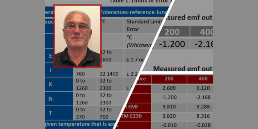
![]() Are you a heat treater who makes thermocouples? How do you stay within limits? What do you need to know when using specific thermocouple materials? Read all about it in this Heat Treat Today Original Content article by Ed Valykeo, thermocouple specialist at Pelican Wire, Naples, FL.
Are you a heat treater who makes thermocouples? How do you stay within limits? What do you need to know when using specific thermocouple materials? Read all about it in this Heat Treat Today Original Content article by Ed Valykeo, thermocouple specialist at Pelican Wire, Naples, FL.

Thermocouple Specialist
Pelican Wire
We are often asked, what is the difference between special limits of error, standard limits of error, and extension grade thermocouple wire? Today’s discussion will review base metal thermocouple tolerances for special, standard, and extension grade wire. First, we will look at the difference between a thermocouple wire producer and the different types of thermocouple wire users. Then, we will look at emf (electromotive force) data for single leg thermoelements and how to determine temperature deviation. Finally, we will touch on how thermocouple wire is manufactured at the wire producer.
Thermocouples
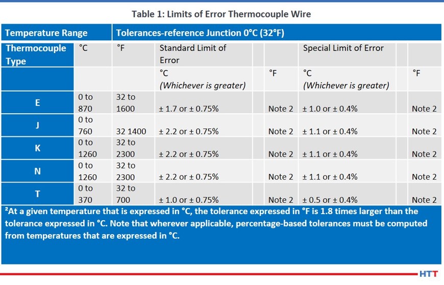
Since thermocouple materials are supplied with different levels of accuracy depending on the standard being used, ANSI/ASTM E230 identifies accuracy requirements for standard limits of error, special limits of error, and extension grade.
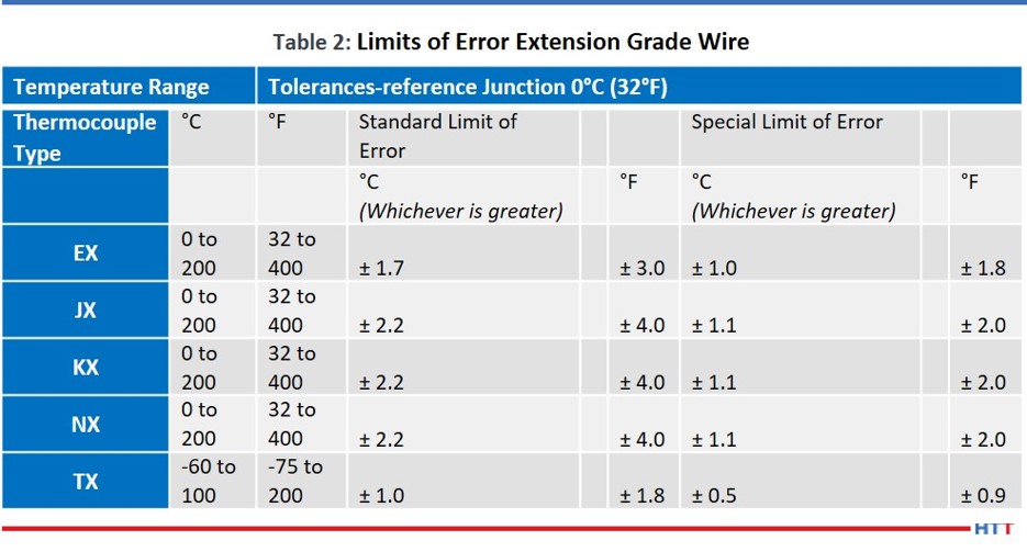
The two tables below list the accuracy requirements for standard, special, and extension grade thermocouples and thermocouple wire.
A thermocouple is a sensor for measuring temperature in which a pair of wires of dissimilar metals are joined at one end. The other end is connected to an instrument that measures the difference in potential created at the junction of the two metals.
From this definition, we know that a thermocouple must have two wires of dissimilar metals. For example, the positive leg (KP) of a Type K thermocouple consists of nickel and chromium, the negative leg (KN) is nickel, aluminum, and silicon. Type J consists of iron in the positive leg (JP) and copper nickel in the negative leg (JN). It has taken decades for thermocouple wire producers to perfect the chemical composition of each thermoelement to achieve desired emf outputs. When these elements are melted, the electromotive force generated can be predicted.
A thermocouple wire producer is where a thermocouple gets its start. Raw chemical elements such as nickel, copper, chromium, manganese, and silicon are melted to form individual thermoelements. The process of melting metals into a usable wire size is done in several ways. A typical method is to melt and pour to form ingots; ingots are then broken down into bar form, and then the bars are hot rolled into rod before the rod is cold drawn to the desired wire size. Producers supply thermocouple materials in rod, wire, and strip form. There are only a few thermocouple wire producers left in the world today.
Measuring Electromotive Force (emf)
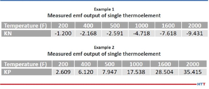
As mentioned above the first step in the life of a thermocouple is the melting step. Chemical elements are gathered and weighed to the desired recipe. The goal is to hit the desired emf curve for a single thermoelement. The process is repeated for the other leg of the thermocouple. Each thermoelement leg is calibrated to get emf data. Once emf data for each leg is known the data can be matched to hit the desired calibration i.e., special, standard or extension grade limits of error. Examples 1 & 2 are emf data provided by a thermocouple wire manufacture. This data is typically posted on each thermoelement spool.
 If the emf data is known for each thermoelement, it is easy to compute the total emf output and temperature deviation in the case that these two spools are combined to make a thermocouple. Below, Example 3 shows how the two individual thermoelements are combined and the resulting emf, and temperature deviations are computed.
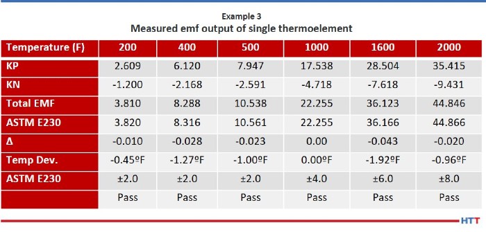
Measured emf output of single thermoelement
Step 1: Algebraically add the emf outputs for both thermoelements at each temperature point. (KP + KN)
Step 2: Take the total emf output of both the KP and KN and subtract value from the tables listed in ASTME230 Standard Specification and Temperature-Electromotive Force Tables for desired thermocouple types.
Step 3: Take the delta value and divide by 0.022mv. (For Type K, the nominal millivolts (mv) per degree is 0.022)
The results show that as a thermocouple, the material meets special limits of error.
Factoid: One quick rule of thumb for Type K Special Limits is ±2.0°F up to 500°F and then ±0.4%.
Buying and Using Bare Wire
It is important to understand thermocouple wire producers sell bare wire in matched sets. By selling in matched sets the producer can guarantee the total emf output falls within special, standard, extension grade limits of error. As mentioned earlier, wire producers melt thermoelements to a precise “metallurgical recipe.” Even though these recipes have been proven out over time, there are still factors which affect the emf output. For example, impurities in raw materials, condition of the furnace and melting practices all contribute to emf results. Since thermocouple wire producers know the emf output of each thermoelement they can mix and match melts to minimize any scrap.
Caution should be taken if bare wire thermocouples are going to be fabricated from positive and negative legs that have not been matched by the wire producer. Any one individual thermoelement can have emf output that, when matched with the opposite leg, could cause the total emf output to fall outside the required tolerances.
If we required special limits of error thermocouples the results of matching the KP and KN leg in Example 4 below, shows the material would not meet special limits at 200 and 1,000 degrees.
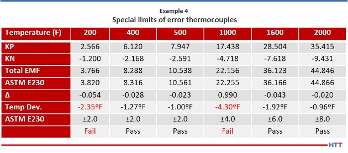
The example of KP and KN shown in Example 4 does not meet special limits of error at 200ºF and 1000ºF. What about standard or extension grade tolerances?
Reviewing Table 1, we can see that the tolerance for standard limits of error is ± 2.2ºC or ± 0.75%. By applying note 2 the tolerance for standard limits of error at 200ºF is ±4.0ºF so this combination of KP and KN would meet the tolerances for standard limits at 200ºF. At 1000ºF the tolerance for standard limits is computed as 1000ºF X .75% or ±7.5ºF. This combination does in fact meet the standard limit tolerance at 1000ºF.
What about extension grade? Would the above KP and KN meet extension grade tolerances? Let us refer to Table 2. Table 2 shows that from 32ºF to 400ºF for special limit extension grade the tolerance is ±2.0ºF. Our matched KP and KN above has a temperature deviation at 200ºF of -2.35ºF. This match would not meet the requirements of special limit extension grade at 200ºF. However, this combination would meet the special limits requirement at 400ºF. What about standard limits extension grade? This combination would in fact meet the tolerances for standard limit extension grade.
Factoid: The tolerances for special limits, standard limits, and extension grade, thermocouples and thermocouple wire are the same! The only difference is that EX, JX, KX, and NX extension grade have a maximum temperature range of 400ºF. Maximum temperature range of TX is 200ºF.
Types of Thermocouple Users
One type of thermocouple wire user, whom we will call an intermediate user in this article, receives the bare wire from the producer and performs additional processing. This processing typically consists of adding an insulation of fiberglass, high temperature textile, extruded thermoplastic or tape to the individually matched pairs, then commonly adding an outer jacket over both thermoelements. There are any number of custom constructions that can be part of this processing, including but not limited to shielding, metal over-braid, multi-pair cabling and combinations or layers of the above insulations. The bare wire can also be incorporated into a mineral insulated cable. Careful consideration is taken to ensure only the two thermoelements matched originally by the bare wire producer are used in the processing. After the insulation process, the wire is then ready to be sent to another type of thermocouple wire user or consumer.
Very commonly, an intermediate user, like Pelican Wire, sends the processed bulk wire to temperature sensor manufacturers. Although not an end user, these sensor manufacturers would still be considered users of thermocouple wire. However, they are distinguished from intermediate users, because of the assembly or fabrication work they perform with the wire. As stated previously, it is crucial the wire be sent to the sensor manufacturers in matched pairs to ensure the calibration accuracy of the wires.
Simply put, an end user is an entity which uses a thermocouple sensor for measuring and monitoring temperature in a manufacturing, or laboratory environment. Examples of this are heat treating metals, curing composites, food & drug processing, monitoring in the oil & gas sector and power generation. The critical nature of the outcomes of these processes point to the importance of accuracy and reliability in a thermocouple and thermocouple wire. An important element of this is understanding calibration of thermocouple wire and the Limits of Error classifications.
There is more information that cannot be covered in this discussion. If you are an end user with questions regarding this subject it would be advisable to contact an experienced thermocouple wire user who processes and does assembly work regularly with the wires for additional guidance.
About the Author: Ed Valykeo, a 40-year veteran in the wire industry, many with Hoskins, is a thermocouple specialist who has worked with Pelican for 10 years.
All tables provided by Ed Valykeo at Pelican Wire.