This article was written by Dr. Vadims Geza, chief scientist at CENOS. More information on CENOS Platform can be found here.
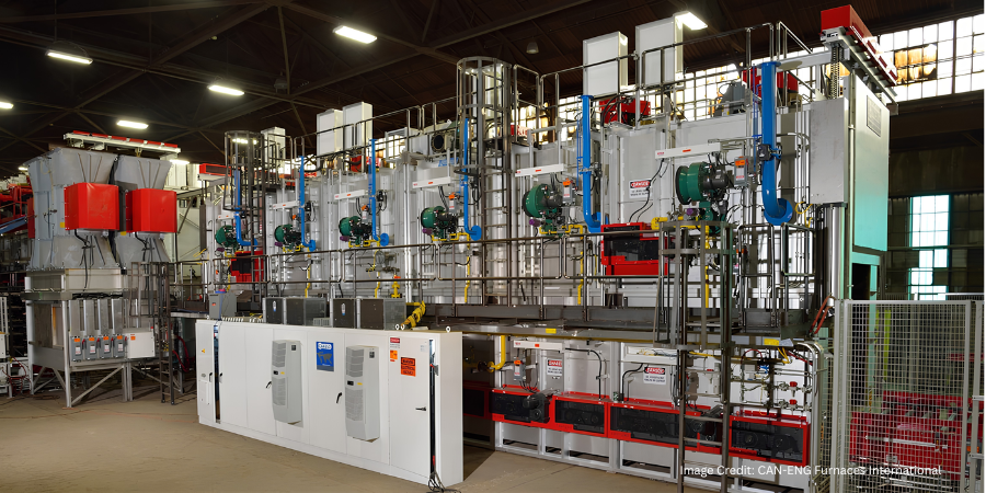
Induction is becoming an increasingly popular choice for heating steel billets prior to forging due to its ability to create high heat intensity quickly and within a billet, which leads to low process-cycle time (high productivity) with repeatable high quality, occupying minimal space on the shop floor. It is more energy-efficient and inherently more environmentally friendly than most other heat sources for steel billets.
In this article, the author demonstrates a simulation example on how to optimize a progressive induction heating system for a steel billet. The method used is CENOS Platform, a 3D simulation software which focuses specifically on induction heating and uses open source components and algorithms.
CENOS platform is capable of simulating various types of induction heating for forging. It is possible to simulate both static heating and progressive heating where the billet is moved through the coil with constant velocity. In accomplishing this simulation, coil design is not a limitation: both single coil and multi-coil are possible to simulate. Besides the coil, it is also possible to simulate any material and frequency.
The functional performance of the software
CENOS is a finite element method-based, computer-aided engineering desktop software for 2D and 3D physical process simulation and computational modeling of induction heating, induction hardening, brazing, annealing and tempering of steel, aluminum, copper, and other materials.
The simulation process consists of three steps:
-
Choose the workpiece geometry (from built-in templates or create your own CAD file).
-
Define induction heating parameters (frequency, voltage, time, etc.).
-
Run 2D or 3D simulation of your choice.
At the conclusion, results like temperature and magnetic field are displayed in 3D renderings, plots, and more. Apparent power, induced heat, and inductance are logged into an Excel file.
3D Simulation example—comparison of two heating systems
In the simulation, two systems under consideration—two-stage and three-stage systems—in the progressive heating of the billet. The target for the simulation was to reach 2192°F (1200°C) ± 122°F (50°C). To check both systems, the user has to create set up for both of them, set physical parameters (material properties, frequency, current, etc.), and start the simulation.
After the simulation is done, the user will have access to different output variables, including:
- Temperature distribution
- Current density and Joule heat distribution
- Magnetic field lines
- Total, reactive and apparent power
- Inductance of the coil
- Coil current, voltage
In our example of billet heating, it is possible to compare both cases and the output.
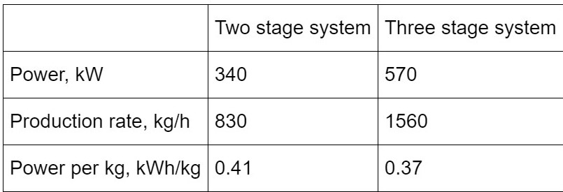
It is observable how a three-stage system can decrease power consumption and increase the production rate for this specific case. It is also possible to plot the distribution of temperature, Joule heat, magnetic field, etc. Resulting temperature distribution in the billet across the radius is shown in Figure 1. As can be seen, better temperature homogeneity is obtained in the three-stage system.
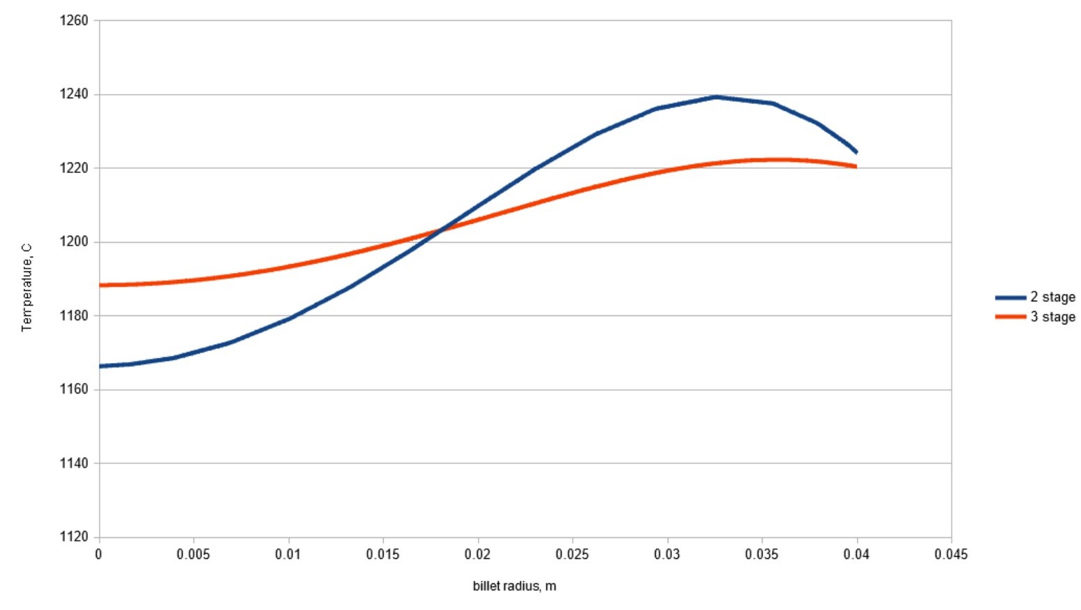
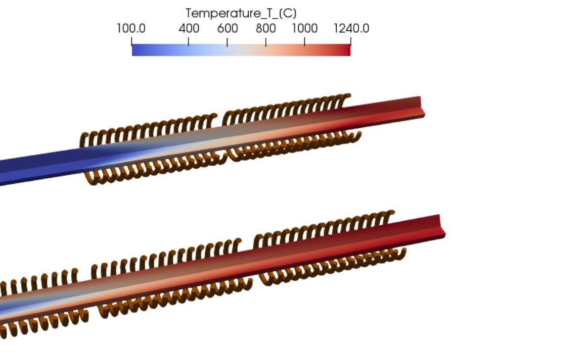
Figure 2 shows how different systems lead to different temperature distribution. In the two-stage system, the temperature required for forging is reached with shorter coils, thus also with smaller scanning speed. This leads to worsened temperature uniformity and smaller production rates. On the other hand, the three-stage system heater gradually increases the temperature of the billet and the resulting temperature difference between core and surface is smaller.
Platform users are free to change all the input parameters and assemble the system of any number of stages required for their process.
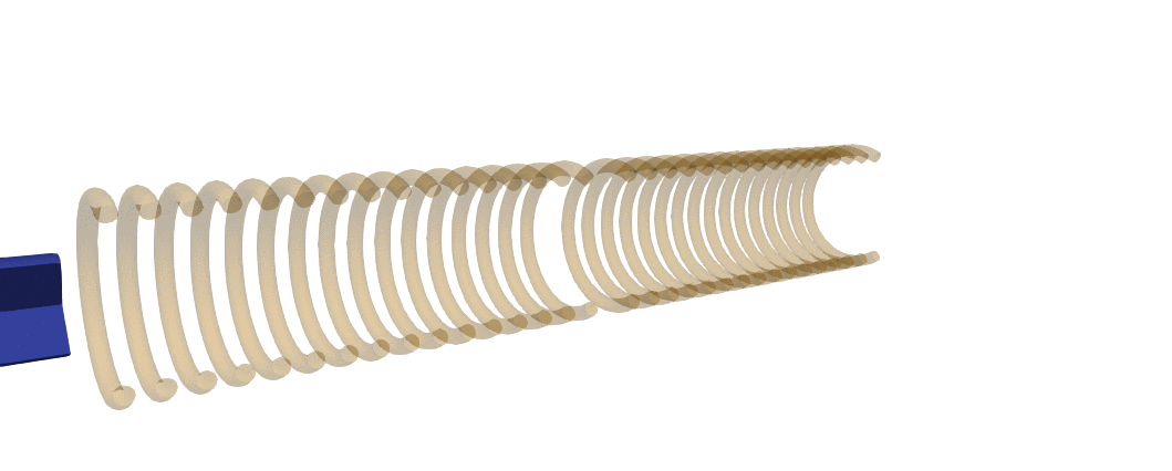
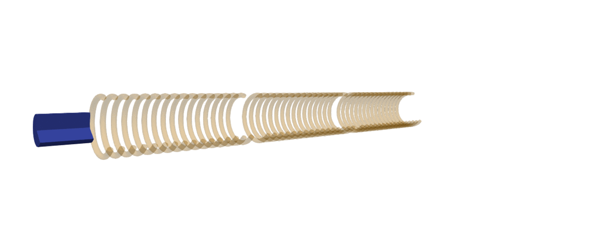
Should the same system need to be used for scanning of shorter billets where end effects play a more significant role, it is possible to set up a simulation with a moving billet. An example of temperature dynamics in such simulation are shown in GIF images below:
Simulation helps make better decisions for production set-up and planning
As demonstrated in the simulation example, it is possible to compare two different systems and get results. The scope and variety of different simulations are unlimited; it all depends on what problem the user wants to solve:
-

Dr. Vadims Geza Heating system design—to optimize induction heating performance, improve product quality, and avoid unpleasant surprises related to subsurface overheating
-
The selection of power, frequency, and coil length in induction billet heating applications
-
The selection of right forging temperatures for plain carbon and alloy steels to avoid possible damage by incipient melting or overheating.

Main Photo Image via CENOS, courtesy of efd-induction.com