![]()
Tempering. A vitally important step in the hardening process and a process that is used extensively throughout the heat treatment industry. There are three main schools of thought on how to achieve a properly tempered part. Here we have asked three experts to share their knowledge on the specific approach they feel works best for tempering: Bill Stuehr of Induction Tooling, Mike Zaharof of Inductoheat, and Mike Grande of Wisconsin Oven. Learn how each approaches tempering and why they feel it works well for them.
Please note that mechanical properties and microstructure, in addition to hardness, need to be carefully considered when choosing any tempering process so as to help ensure the part is fit for its intended purpose.
This Technical Tuesday article first appeared in Heat Treat Today’s May 2022 Induction Heating print edition.

Induction Tempering: Captive Heat Treating
By William I. Stuehr, President/CEO, Induction Tooling, Inc.

President/CEO
Induction Tooling, Inc.
I can only speak to this subject through a lens of 46 years and thousands of induction hardening applications. That said, I have had many tempering inductor requests within the domain of captive heat treating. The commercial induction heat treaters that I service most always use oven tempering because it is accurate, economical, and easy.

Source: Induction Tooling, Inc.
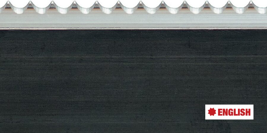
For the captive heat treat departments processing high volume components, the interest in induction tempering as an in-line process sparked in the mid-1970s with the production “cell” concept. This was most evident in the manufacturing of modular wheel bearing assemblies – raw forgings were fed into the cell and completed units exited. Modular wheel bearings are composed of a hub and a spindle. Within the production cell both needed selective induction hardening and tempering. The specification for the wheel spindle required a casehardened profile to provide wear and strength and for the wheel hub, the bearing races were hardened. Equipment manufacturers designed and built specialized high-volume parts handlers, integrated with the proper induction power supplies to operate efficiently within the cell. The inductors, both hardening and tempering, were designed, built, and characterized to produce a specification hardened part (Figure 1).
Source: Induction Tooling, Inc.
Induction Tooling, Inc.
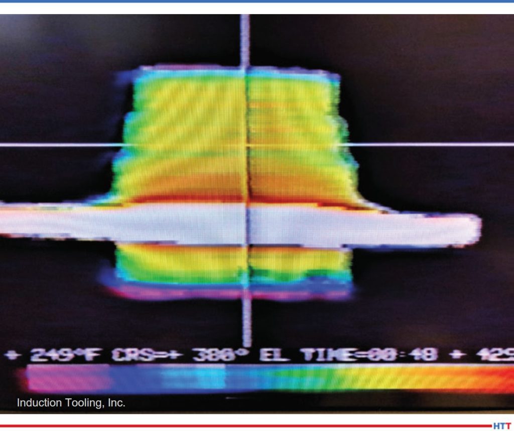
Induction hardening for the hub and spindle is quick – usually five seconds or less; induction tempering is a much longer heating process. Both parts required a low power soak until the optimum temperature was achieved. For the two wheel bearing components, tempering had to be accomplished either in a long channel-type inductor or several multi-turn inductors to keep pace with hardening. The long channel inductor was designed to hover over a conveyor belt. The belt would move the hardened hub or spindle at a slow, even pace allowing the precisely controlled induction energy to migrate throughout. Care was taken in the design and length of the channel inductor to assure temperature uniformity. Multi-turn inductors are circular solenoid designs that required the hub or spindle to lift and slowly rotate at three or four locations in order to complete the temper. As in hardening, the temper installation required its own induction power supply. Thermal imaging confirmed the results (Figure 2).
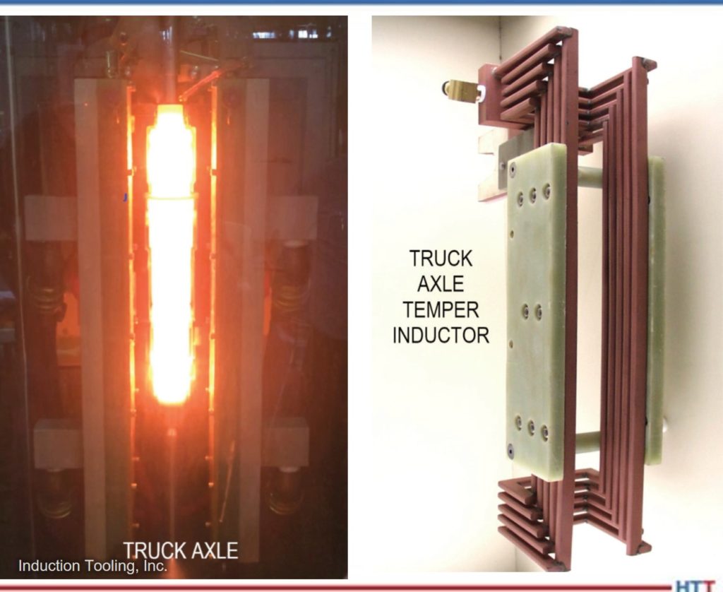
Truck axle shafts are another high production component that is induction hardened and tempered. Often the axle shafts are robotically loaded in a vertical or horizontal inductor. The shaft is rotated, heated, and then shuttled to a quench position. The loading robot then moves the hardened axle shaft to another inductor, usually within the same unit, specifically designed for the tempering process. A separate induction power supply controls the input energy. The temper time can be equal to the induction hardening time added to the quenching time. This will allow for the proper input of uniform induction temper energy (Figure 3).
Today, high production automotive driveline components are routinely induction tempered. Among the examples explained are CV joints, gears, and camshafts. Monitoring of the induction energy is different compared with furnace tempering. When heating parts with complex geometries, it is necessary to focus upon where the induction energy is concentrated. Heat conduction can be carefully monitored to confirm that an overheat condition does not occur at the target temper areas. Power input, soak time, and inductor characterization control these
fundamentals.
Induction tempering is sometimes attempted using the hardening inductor. For some very low volume parts, depending upon the part geometry and induction power supply frequency, the results may be acceptable. Careful power control and timing along with thermal imaging is needed to confirm the results. Again, since tempering takes longer, output will be much slower. Experience has demonstrated that a part specific tempering inductor coupled with a dedicated induction power supply works best.
About the Author: Bill Stuehr is the founder and president of Induction Tooling, Inc, a premier heat treat inductor design and build facility. The holder and partner of many induction application patents, Bill shares his expertise and generously donates his time and facility resources to mentor young students entering the heat treat industry.
For more information: bstuehr@inductiontooling.com

Induction Tempering: The Basics
By Michael J. Zaharof, Customer Information & Marketing Manager, Inductoheat

Customer Information & Marketing Manager
Inductoheat
Induction tempering is the process of heating a previously hardened workpiece to reduce stress, increase toughness, improve ductility, and decrease brittleness. A medium-to-high carbon steel (i.e., 1045, 1050, 4140, 5160) heated above the upper critical temperature causes a high-stress shear-like transformation into very hard and brittle martensite. This untempered martensite is generally undesirable and too brittle for postprocessing operations such as machining and can pose a concern for poor performance in high fatigue applications. Therefore, tempering is needed to reduce internal stresses, increase durability, and reduce the possibility of cracking.
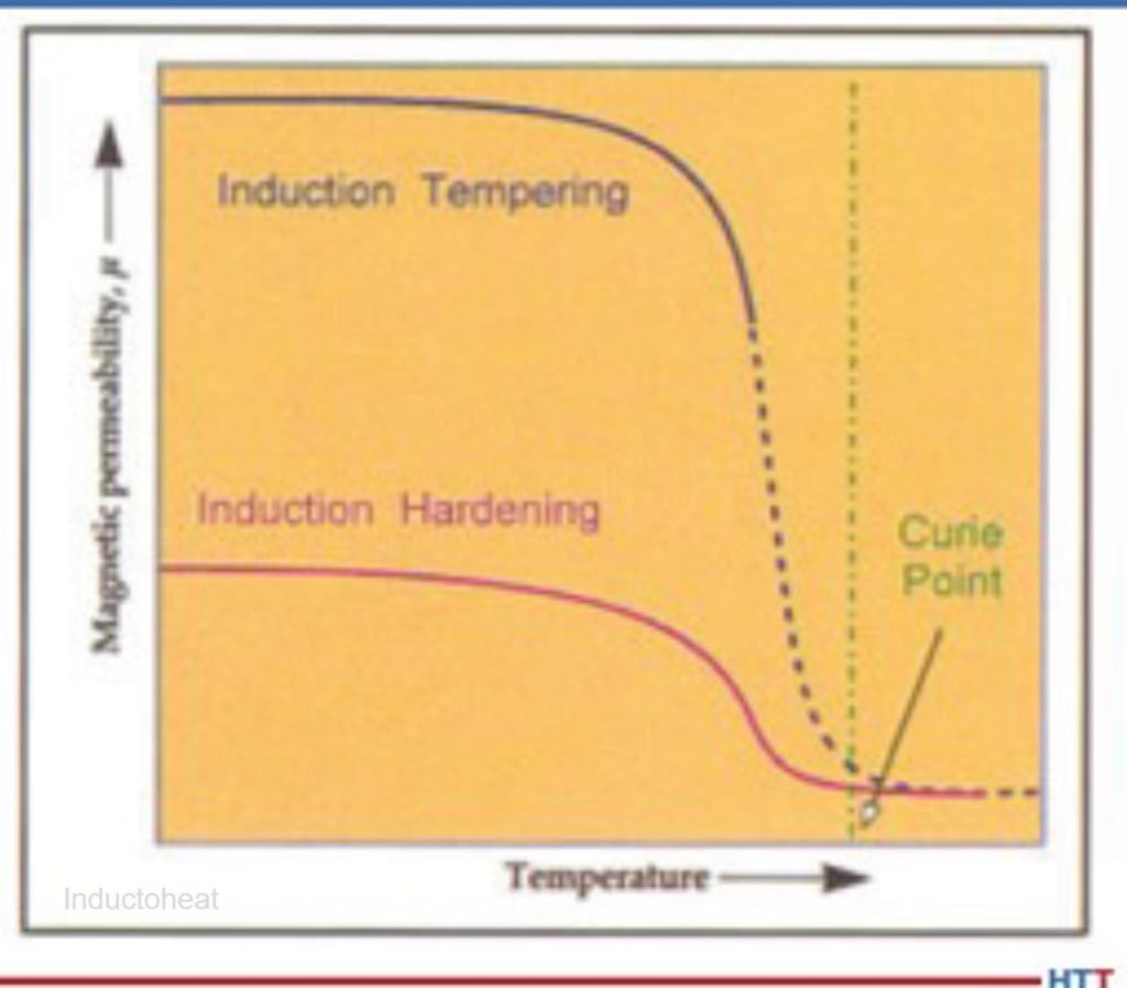
In most cases, induction tempering occurs in-line and directly after the induction heating, quenching, and cool-down operations. Traditionally, workpieces are moved to a tempering spindle or separate machine after hardening. Once moved, the part is then inductively heated and often force cooled to ambient temperature. The induction tempering process itself generates temperatures on the workpiece (typically) well below the curie point (248°F-1112°F/120°C-600°C – solid blue line in Figure 1). This phenomenon is referred to as “skin effect,” where the current density is highest at the surface of the material. Therefore, a lower inverter frequency is most desirable in order to increase the electrical reference depth.
However, while most cases reflect a secondary/separate station for induction tempering, this is not always the case. Recent advancements in power supply technology permit “real-time” frequency and power adjustments. These next-generation induction power supplies have brought tremendous flexibility into the market and have allowed induction hardening and tempering to occur at the same station, on the same induction coil. Using such a novel approach with induction heating often speeds up production while reducing the number of part movements. Induction tempering is a preferred method for many manufacturers as it offers several notable advantages. In production applications, it is viewed as a fast-tempering method, as the parts are heated quickly, cooled, then moved on to the next operation, reducing potential bottlenecks.
There is no need to collect the parts, place them into batches, and wait for long subsequent processes to finish before moving them down the production line.
Source: Inductoheat
Induction is a clean process and does not rely on combustible gases or chemicals that may be harmful to the environment. Additionally, it is also a very efficient process as induction power supplies are only powered on when needed compared to batch processing (like those requiring an oven). Ovens must be preheated prior to use and can often stand idle for long periods between batches, as the pre-heat/cooldown cycles can be lengthy. Induction heating equipment is also physically smaller in most cases and occupies much less real estate on the manufacturing floor.
Individual part traceability and data collection are possible when utilizing induction tempering. If paired with a quality monitoring system (QAS), data can be evaluated in real-time and compared to a known good “signature” for the part during the induction tempering process. This allows precise control of the process and the ability to reject parts that deviate outside of established metrics. It is also an effective tool for detecting process issues early when a variation occurs minimizing potential scrap and helping to prevent delivery of “bad” parts to the end customer.
Induction tempering offers many advantages over other methods of tempering and is an effective choice in many applications. Due to the benefits of speed, efficiency, repeatability, and environmental cleanliness, induction technology is widely accepted and is being used throughout many industries today.
References:
[1] “In-Line Tempering on Induction Heat Treating Equipment Relieves Stresses Advantageously,” by K. Weiss: Industrial Heating, Vol. 62, No. 12, December 1995, p. 37-39.
[2] “Induction Heat Treatment: Basic Principles, Computation, Coil Construction, and Design Considerations,” by V.I. Rudnev, R.L. Cook, D.L. Loveless, and M.R. Black: Steel Heat Treatment Handbook, G.E. Totten and M.A.H. Howes (Eds.), Marcel Dekker Inc., Monticello, N.Y., 1997, p. 765-871.
About the Author: Michael Zaharof is a customer information & marketing manager at Inductoheat in Madison Heights, Michigan. He has been with the company since 2011 and has worked in the sales application, digital media, outside sales, and engineering departments. Michael has a bachelor’s degree in computer science in information system security.
For more information: mzaharof@inductoheat.com

Oven and Furnace Tempering
By Mike Grande, Vice President of Sales, Wisconsin Oven

Vice President of Sales
Wisconsin Oven
Tempering (also known as “drawing”) is a process whereby a metal is heated to a specific temperature, then cooled slowly to improve its properties. It is commonly performed on ferrous alloys such as steel or cast iron after quench hardening. Quenching rapidly cools the metal, but leaves it brittle and lacking toughness, which is a desirable characteristic that represents a balance of hardness and ductility. After quenching, the material is tempered to reduce the hardness to the required level and to relieve internal stresses caused by the quenching process. The resulting hardness is dependent on the metallurgy of the steel and the time and temperature of the tempering process. Tempering is performed at a temperature between approximately 255°F (125°C) and 1292°F (700°C). In general, tempering at higher temperatures results in lower hardness and increased ductility. Tempering at lower temperatures provides a harder steel that is less ductile.
Wisconsin Oven
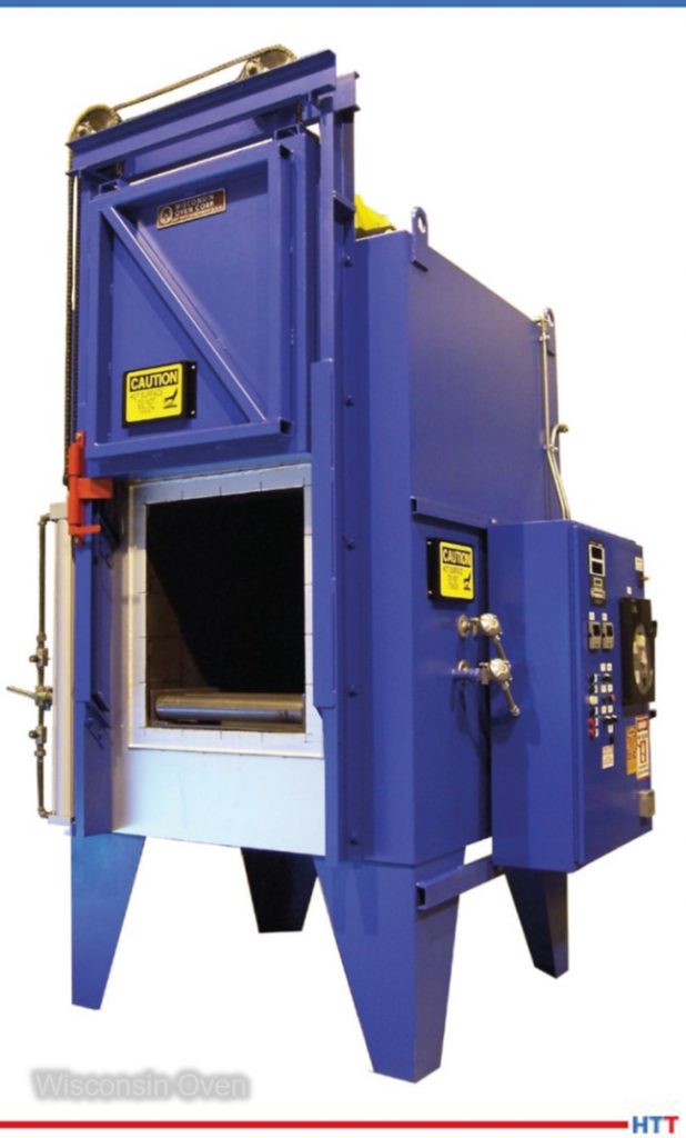
Tempering is performed in a convection oven using a high volume of air circulating through and around the load of steel being tempered. The air is heated in a plenum separated from the load, then delivered to the load at high velocity through distribution ductwork using a recirculation blower. Since the air is the medium used to carry the heat from the source (a gas burner or heating elements) to the load, it is important that the blower recirculates a high volume of air through the heating chamber. Further, since air becomes significantly less dense at higher temperatures, the recirculated air volume must be higher for ovens operating at higher temperatures in order to provide sufficient mass (pounds or kilograms) of air to transfer the heat from the source to the load.
For example, a typical batch tempering oven designed to process a 2,000 lb. load with dimensions of 4′ x 4′ x 4′ might have a recirculation rate of 10,000 cubic feet per minute (CFM). At this airflow volume, the oven recirculating system operates at 156 air changes per minute, which means all the air passes from the recirculating blower through the heating chamber 2.6 times per second. At a temperature of 1000°F (538°C), for example, the weight of the air being recirculated is 290 lbs. (132 kg) per minute, or 17,400 lbs. (7,909 kg) per hour. It is this high volume of air that provides good heat distribution to the load being processed and ensures tight temperature uniformity within the load during tempering.
The higher the mass of air being recirculated, the tighter the temperature uniformity will be. The temperature uniformity (±10°F or 6°C, for example) defines how much the temperature is allowed to vary within the load being tempered. If the oven operates too far outside of this tolerance, the parts may not be tempered uniformly, and the hardness might vary among different parts in the same load. It is important that the temperature uniformity of a tempering oven be verified (“certified” or “qualified”) by testing, and that this is repeated periodically, as well as after any changes or repairs are made that could affect the uniformity.
About the Author: Mike Grande is the vice president of Sales at Wisconsin Oven with a bachelor’s degree in mechanical engineering and over 30 years of experience in the heat processing industry. Over that time, he has been involved with convection and infrared technologies, and several industrial oven energy efficiency design advancements.
For more information: 262-642-6003 or mgrande@wisoven.com
 Rapid Air Tempering
By HTT Editorial Team
The next type of tempering we’d like to address is rapid air tempering. This process involves “any tempering technology taking advantage of rapid heating methods combined with shortened soak times at temperature based on those predicted by use of the Larsen-Miller calculator.”1 Here “rapid heating” is defined as “any heating method that accelerates conventional furnace heating.”2
Rapid air tempering takes advantage of the use of a higher initial heating temperature (i.e., the use of a so-called heat head) to drive heat into the part more quickly. Additionally, rapid air tempering shortens soak time at temperature (from the more conventional furnace tempering times).
The Larson-Miller calculator is used in rapid air tempering to provide a comparison of hold times at various tempering temperatures and the results of tempering time change is assumed be the same (see example below); however, the interpretation of the data and results are left to the end user.
Larson-Miller Calculator
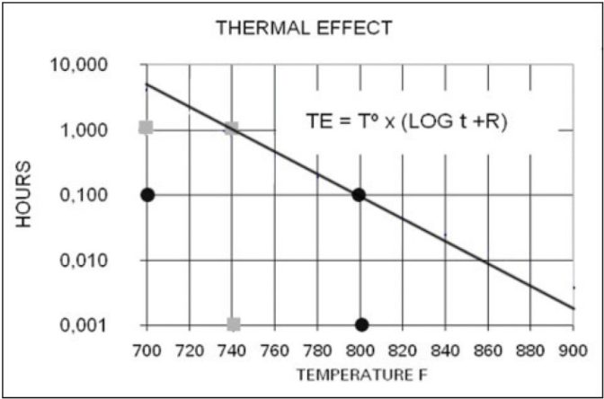
There are various reports describing the use of the Larson-Miller equation for assessing stress-relieving and tempering process conditions.4 “The relationship between time and temperature can be described as a logarithmic function in the form of the Larson-Miller equation, which shows that the thermal effect (TE) is dependent on the temperature and the logarithm of time:
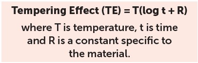
“This thermal effect is also interpreted as the tempering parameter. For example, a material that is required to be tempered at a temperature of 740°F for one hour has the same TE as a material treated at 800°F for 6 minutes (Fig. 1).”5
References:
[1] Roger Gingras, Mario Grenier, and G.E. Totten, “Rapid Stress Relief and Tempering,” Gear Solutions, May 2005, pg. 27-31.
[2] N. Fricker, K.F. Pomfret, and J.D. Waddington, Commun. 1072, Institution of Gas Engineering, 44th Annual Meeting, London, November 1978.
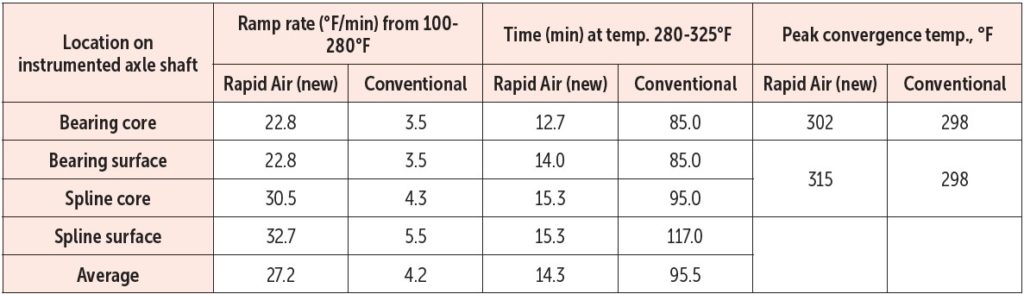
[3] Thomas Neumann and Kenneth Pickett, “Rapid Tempering of Automotive Axle Shafts,” Heat Treating Progress, March/April 2006, pg. 44.
[4] Lauralice C.F. Canale, Xin Yao, Jianfeng Gu, and George E. Totten, “A Historical Overview of Steel Tempering Parameters,” Int. J. Microstructure and Materials Properties, Vol. 3, Nos. 4/5, 2008, pg. 496.
[5] Roger Gingras and Mario Grenier, “Tempering Calculator,” in ASM Heat Treating Society, Heat Treating: Proceedings of the 23rd ASM Heat Treating Society Conference September 25-28, 2005, David L. Lawrence Convention Center, Pittsburgh, Pennsylvania, USA, Daniel Herring and Robert Hill, eds., Materials Park, Ohio: ASM International, 2006. pg. 147-152.