Ask The Heat Treat Doctor® has returned to bring sage advice to Heat Treat Today readers and to answer your questions about heat treating, brazing, sintering, and other types of thermal treatments as well as questions on metallurgy, equipment, and process-related issues. In this installment, Dan Herring discusses the science behind pH — what it really measures, and why it matters — and offers practical guidance on monitoring water quality in open and closed systems found throughout the heat treat shop.
This informative piece was first released in Heat Treat Today’sMay 2026 Sustainable Heat Treat Technologies print edition.
Introduction to pH
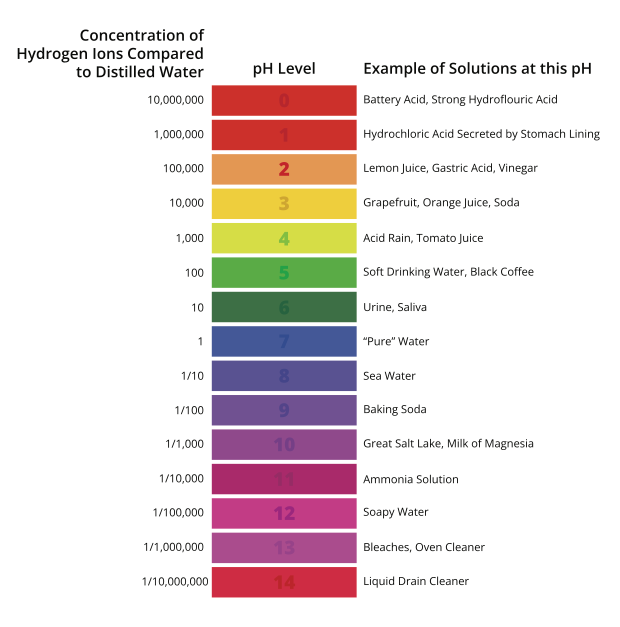
The term “pH” is used to describe a unit of measure that indicates the degree of acidity or alkalinity of a solution. It is measured on a scale of 0 to 14 (Table A). pH is an abbreviation that stands for the “potential of hydrogen”; the “p” being the symbol for potential (or power) and “H” the symbol for hydrogen.
Table A. pH Chart (Herring 2015b)
A Slightly Deeper Dive
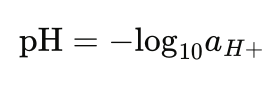
What most people don’t realize is that pH is a complex concept rooted in chemical equilibrium, thermodynamics, and electrochemistry. The formal definition of pH is “the negative logarithm of the hydrogen ion activity” and can be expressed mathematically by the following formula where au+ is the activity of hydrogen ions, a dimensionless quantity (Rumble 2024):
In this form, pH provides a way of expressing the degree of the activity of an acid or base in terms of its hydrogen ion activity. Acids and bases have, respectively, free hydrogen [H+] and free hydroxyl [OH−] ions. Since the relationship between hydrogen ions and hydroxyl ions in a given solution is constant for a given set of conditions, either one can determine the other. In other words, pH is really a measurement of both acidity and alkalinity, even though by definition it is a selective measurement of hydrogen ion activity.
Since pH is a logarithmic function, a change of one pH unit represents a tenfold change in hydrogen ion concentration, that is, of both the hydrogen ion and the hydroxyl ion at different pH values (Table A). Note that each decrease in pH by one pH unit means a tenfold increase in the concentration of hydrogen ions.
A Little Chemistry
In school, we learned that all substances are made up of millions of tiny atoms. These atoms combine to form molecules. In water, for example, each molecule is made up of two hydrogen (H) atoms and one oxygen (O) atom. The formula for a molecule of water is expressed by the familiar symbol H2O. That is, there are two hydrogen atoms needed for each oxygen atom to form a stable compound.
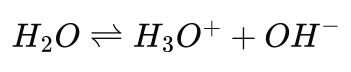
Now, the behavior of pH in aqueous systems is governed by the equilibrium of water to form positive and negative ions (so-called self-ionization), which can be expressed as:
or in the following form we more commonly think of:
Hency, at 25°C (Kw = 1.0 x 10⁻¹⁴), the equilibrium constant for this process is:
Then for pure water, where aH+ = a0H-, we have that aH+ = 10-7 hence pH = -log10 (10-7) = 7.00 which is neutrality at 25°C (77°F).
Finally, it is important to note that Kw is temperature-dependent: it increases with temperature, meaning neutral pH decreases slightly as temperature rises (e.g., ~6.14 at 100°C). Therefore, “neutral pH” is not always 7 — it depends on thermal conditions.
A Practical Application — Water Quality in the Heat Treat Shop
Water is used in most of our heat treat shops for a variety of purposes, perhaps less than before but still vitally important. Examples include parts washers, heat exchangers, water cooled bearings on fans and rolls, seals on pit furnace covers, water cooled jackets on continuous furnaces, water cooled jackets for quench tanks, top or side cooling chambers, inner doors and plate coils, and make up water for water systems, to name a few.
Table B. Typical Water Requirements for Open Systems (Decelles 2002)Table C. Water Requirements for Closed Hydronic Systems (Heatlink Group 2006)
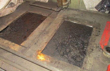
Water quality requirements are often defined differently for open systems (Table B) and closed (recirculated) systems (Table C). Open systems are typically more problematic as the issue of water quality varies. Water is often classified as “soft” or “hard” depending on its mineral content (i.e., the amount of calcium and magnesium dissolved in the water). Soft water has an ideal hardness of approximately 120 ppm (7 grains/gallon). Hard water often results in the formation of mineral deposits, which can lead to blockages in water systems (Figure 1).
Figure 1. Sludge buildup and flow blockage in the top cool of an integral quench furnace | Image Credit: The HERRING GROUP, Inc.
Furthermore, we must ensure that the water being discharged from our heat treatment operations is clean and meets EPA standards. Finally, we must be especially careful to avoid cross-contamination from other sources in the shop (e.g., polymers, quench oils, chemicals).
In Summary
Two little consonants, pH, are deceptively simple yet so profoundly important. They represent the thermodynamic state of solutions, but in reality, link microscopic interactions with real world issues. As heat treaters, our focus is to not take our water supply and water systems for granted since unexpected surprises, unwanted downtime, and expensive repairs can result. When is the last time you tested your water?
References
Herring, Daniel H. 2015a. Atmosphere Heat Treatment. Vol. 2. Southfield, MI: BNP Media.
Herring, Daniel H. 2015b. “The Importance of pH.” Industrial Heating, January.
Heatlink Group. 2006. Water Quality in Hydronic Systems. June 21, 2006. https://www.heatlink.com/sites/default/files/Info%20Sheet/L2329-Water-Quality-in-Hydronic-Systems-2006-06-21.pdf.
Decelles, P. 2002. The pH Scale. Johnson County Community College. Archived webpage. http://staff.jccc.net/pdecell/chemistry/phscale.html.
Rumble, John R., ed. 2024. CRC Handbook of Chemistry and Physics. 105th ed. Boca Raton, FL: CRC Press.
About the Author
Dan Herring “The Heat Treat Doctor” The HERRING GROUP, Inc.
Dan Herring has been in the industry for over 50 years and has gained vast experience in fields that include materials science, engineering, metallurgy, new product research, and many other areas. He is the author of six books and over 700 technical articles.
Cuando una carga se atasca durante el temple, cada segundo cuenta y las decisiones improvisadas pueden aumentar el riesgo. En esta entrega de “Martes Técnico“, Bruno Scomazzon, gerente general de Precision Heat Treat Ltd., describe un procedimiento de respuesta de emergencia paso a paso para este escenario, uno de los más peligrosos en el tratamiento térmico con atmósfera. Basándose en la experiencia real, esta guía tiene como objetivo ayudar a las empresas a desarrollar sus propios procedimientos eficaces para mantener la seguridad, controlar las condiciones del horno y coordinarse con los servicios de emergencia en situaciones de alto riesgo.
Este artículo informativo se publicó por primera vez en Ingles enHeat Treat Today’sFebruary 2026 Annual Air & Atmosphere Heat Treating print edition.
Si tiene comentarios o preguntas sobre este artículo, háganoslo saber en: editor@heattreattoday.com.
Traducido por Víctor Zacarías. To read this article in English, click here.
Descripción del escenario
Se ha transferido una carga a la cámara de temple y el elevador está descendiendo al aceite, pero la carga se atasca y no se sumerge por completo. La puerta interior se cierra correctamente, y la puerta exterior (frontal) permanece cerrada.
Esta es una situación de altísimo riesgo que requiere el estricto cumplimiento de los procedimientos de emergencia. El objetivo es proteger: primero al personal (minimizar la posibilidad de lesiones o que la situación empeore), luego las instalaciones y, finalmente, el equipo.
1. Medidas inmediatas
NO abra la puerta exterior
Es posible que sienta la tentación de evaluar la situación, pero resista la tentación. NO se coloque frente a la puerta exterior ni justo al lado de ella, y nunca la abra mientras la carga esté “colgada”. Abrir esta puerta puede introducir oxígeno en una cámara caliente, lo que provocaría:
Explosiones o incendios repentinos (flash fire).
Pérdida de contención debido a deformación de la puerta o falla mecánica.
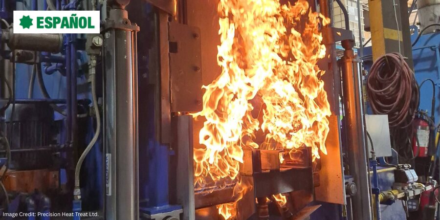
En casos extremos, la puerta exterior puede resultar dañada (arrancada, atascada o parcialmente abierta) y presentar llamas visibles. Esto requiere alertar inmediatamente a los bomberos.
Si la puerta exterior no se puede cerrar
En este caso, notifique inmediatamente a los bomberos e indíqueles que se preparen para una respuesta con espuma. NO permita el uso de agua. ¡Esto podría provocar reacciones violentas con el aceite o la atmósfera y propagar el fuego!
El personal de respuesta capacitado debe:
Colocarse el equipo de protección personal (EPP).
Preparar el equipo de extinción de incendios.
Estar listos para proteger los sistemas críticos hasta que lleguen los bomberos.
NO apague el horno.
Figura 1. Horno de atmósfera durante su operación normal. | Image Credit: Precision Heat Treat Ltd.Figura 2. Puerta del vestíbulo parcialmente abierta durante una simulación controlada para | Image Credit: Precision Heat Treat Ltd.
2. Mantener el suministro eléctrico
Para garantizar que los sistemas esenciales permanezcan activos, debe mantener el suministro eléctrico. Asegúrese de que los siguientes sistemas permanezcan activos:
Cambie el modo del horno de automático a manual. Esto evitará cualquier secuenciación del PLC que active automáticamente las puertas, los elevadores y los manipuladores.
Mantenga las llamas piloto encendidas.
Mantenga el enfriamiento del aceite en funcionamiento para evitar el sobrecalentamiento del tanque.
Apague los calentadores de aceite para evitar una carga térmica adicional en el tanque de temple.
Mantenga la agitación del temple a baja velocidad durante todo el proceso para ayudar a disminuir la temperatura en la superficie de interfaz entre la carga y el aceite. Esto evita la estratificación y disipa el calor por radiación en el aceite.
Mantenga el recirculador en funcionamiento.
Mantenga la instrumentación en funcionamiento para el monitoreo.
NOTA: La pérdida de estos sistemas elimina la visibilidad, el control de la atmósfera y las opciones de respuesta seguras.
3. Gestión de la atmósfera
Mantenga una atmósfera protectora y una presión positiva en el horno para evitar la entrada de oxígeno y la combustión incontrolada:
Ajuste el control del potencial de carbono a “0”.
Cierre el suministro de gas de enriquecimiento.
Cierre el suministro de amoníaco.
Cierre el suministro de aire de dilución.
Purga de nitrógeno
Estos pasos dependen de si se dispone de una purga de nitrógeno; se recomienda encarecidamente que esté disponible para todas las unidades con temple integral o de paso directo. Asegúrese de comprender cuánto tiempo tarda su horno en purgar completamente el gas endotérmico. Si bien la norma NFPA 86 recomienda cinco ciclos de purga, algunos expertos aconsejan prever hasta diez por hora en caso de emergencia. Cada horno debe contar con datos de purga establecidos en condiciones normales para que los operadores puedan actuar con confianza cuando el tiempo es crucial.
Figura 3. Suministro de nitrógeno utilizado para purga de emergencia y control de la atmósfera. | Image Credit: Precision Heat Treat Ltd.
Inicie inmediatamente una purga de nitrógeno (si está disponible) y manténgala durante todo el evento.
Utilice al menos el flujo mínimo especificado en su documentación. Si es seguro, se puede utilizar un flujo mayor para ayudar a desplazar los gases inflamables de las cámaras de calentamiento y temple.
Mantenga la temperatura del horno a 815°C (1500°F) durante la purga.
Pueden quedar espacios residuales de gas Endo atrapados en zonas con poca ventilación. Si la temperatura de la cámara desciende por debajo del punto de ignición antes de que se haya desplazado todo el gas inflamable, la entrada de oxígeno podría provocar una explosión. En algunos casos, el Endo atrapado y los desequilibrios de presión pueden causar fugas repentinas, en las que se expulsa aceite o gas debido a la acumulación de presión interna.
Después de la purga
El objetivo de la purga con nitrógeno es desplazar el gas endotérmico con una atmósfera inerte, manteniendo una temperatura elevada para facilitar la combustión de los gases inflamables residuales y prevenir la formación de mezclas peligrosas. Este proceso debe garantizar una presión positiva en todo el horno.
Una purga seguida de enfriamiento por inmersión de nitrógeno es un método válido si la purga se ha completado de forma verificable.
Según el tamaño del horno y la velocidad de enfriamiento:
Los hornos más grandes pueden enfriarse lo suficientemente lento como para completar la purga.
Las unidades más pequeñas o de enfriamiento más rápido pueden requerir un breve mantenimiento de la temperatura antes del enfriamiento controlado o el enfriamiento por inmersión.
NOTA: Una vez que la carga suspendida se enfríe a una temperatura segura (aproximadamente 65°C), realice el apagado estándar del equipo.
Sin nitrógeno (en Endo)
Si no hay purga de nitrógeno, o esta es insuficiente, la única opción es dejar que la carga acumulada se enfríe en el vestíbulo mientras se continúa quemando Endo y se mantiene la temperatura del horno a 1500°F. Una vez que el vestíbulo/tanque de aceite se enfríe por debajo de 150°F y haya pasado el peligro, inicie el apagado estándar del horno.
4. Gestión de la seguridad
Alerte inmediatamente al cuerpo de bomberos local. Si la situación se vuelve incontrolable o si existe alguna duda sobre la capacidad de mantener el control, evacúe las instalaciones y espere a que lleguen profesionales capacitados. La seguridad del personal de la planta es primordial.
Notifique al departamento de seguridad de la planta y a la administración del sitio.
Evacúe a todo el personal no esencial del área de tratamiento térmico.
Informe a todos los departamentos que se está produciendo un incidente de alto riesgo.
Los bomberos son más eficaces cuando conocen sus instalaciones antes de que ocurra una emergencia. Asegúrese de que conozcan la distribución de sus operaciones, incluyendo:
Ubicación y tamaño de los tanques de aceite
Paneles eléctricos
Válvulas de cierre de gas
Zonas calientes
5. Periodo de enfriamiento controlado
Mantenga la protección con atmósfera durante todo el evento.
NO abra las puertas hasta que la temperatura del vestíbulo sea baja y estable.
El tiempo de enfriamiento dependerá de la masa de la carga y la retención de calor. Prevea cinco horas o más.
Utilice la estabilidad de la presión del horno, las observaciones de los efluentes y el comportamiento de los gases como indicadores indirectos de la temperatura.
6. Procedimiento de recuperación de la carga
Una vez enfriado y estabilizado, realice el apagado estándar, comenzando con la eliminación del gas endotérmico, si corresponde.
NO intente retirar la carga manualmente hasta que el sistema esté verificado como seguro.
Solo el personal de mantenimiento puede recuperar la carga, utilizando equipo de protección personal (EPP) y las herramientas adecuadas.
7. Familiarización con el cuerpo de bomberos
Toda instalación debe establecer una buena relación con el cuerpo de bomberos local antes de que ocurra una emergencia. Procure revisiones anuales e identifique lo siguiente:
Número de hornos
Volumen de los tanques de aceite de temple para extinción de incendios
Ubicación de las zonas calientes y los paneles de control
Puntos de parada de emergencia
Las puertas atascadas suelen deberse a fallos en las válvulas neumáticas. Cerrar el suministro de aire comprimido y purgarlo puede permitir que el mecanismo se reinicie. Consulte siempre el manual del equipo o al fabricante antes de intentar cualquier solución.
Considere que el inspector de bomberos que realice las revisiones no es necesariamente quien acudirá a combatir los incendios; capacite a quienes sí lo harán.
Protocolo posterior al incidente
Antes de volver a poner en funcionamiento el horno, asegúrese de:
Realizar una investigación formal.
Identificar y corregir la(s) causa(s) raíz.
Documentar todos los parámetros clave y las acciones tomadas.
Capacitar nuevamente a los operadores según sea necesario.
Señalización del horno
Es probable que un operador lea el plan de seguridad, pero podría olvidar un protocolo vital durante una emergencia. Contar con advertencias claras y llamativas, impresas y colocadas en el panel, que el operador pueda retirar y utilizar en caso de emergencia, puede ser de gran utilidad.
Reflexiones finales
No podemos predecir todas las consecuencias. Ningún procedimiento puede contemplar todas las variables posibles en una emergencia real. Una vez que un evento se pone en marcha, lo único que podemos hacer es responder con el mejor criterio, capacitación e intenciones, priorizando siempre la seguridad de las personas.
Este documento pretende ser una referencia práctica: una guía estructurada elaborada con esmero, experiencia real y buenas prácticas. No es una solución universal, sino una herramienta para ayudar a los equipos a crear o mejorar sus propios procedimientos eficaces y a responder de forma adaptativa en situaciones de alto riesgo.
La preparación contra incendios es esencial en toda planta de tratamiento térmico. Los incendios ocurren, y no siempre son pequeños. Es fundamental saber cuándo actuar, cuándo evacuar y cuándo pedir ayuda. Los manuales de equipos proporcionan una base, pero la preparación mediante capacitación y planificación es la mejor defensa.
Agradecimientos: El autor agradecer a Daniel H. Herring, “The Heat Treat Doctor,” a The HERRING GROUP, Inc., y a Avery Bell de Service Heat Treat en Milwaukee por sus valiosas contribuciones.
Acerca del autor:
Bruno Scomazzon Gerente General Precision Heat Treat Ltd.
Bruno Scomazzon es el gerente general de Precision Heat Treat Ltd. en Surrey, Columbia Británica, Canadá, y cuenta con más de 40 años de experiencia en procesos metalúrgicos y operaciones de tratamiento térmico.
In this two-part series, Dr. Gopal Nadkarni, an associate professor of mechanical engineering at the University of Akron, revisits the American origins and impacts of the Jominy test while exploring how rapid quenching technologies are exposing its limitations. Discover how a new approach builds on ASTM foundations to better reflect today’s high-performance cooling methods.
This informative piece was first released in Heat Treat Today’sApril 2026 Annual Induction Heating & Melting print edition.
Introduction
For nearly a century, the Jominy End-Quench Test has shaped how North American engineers design alloys, specify steels, and heat treat critical components across automotive, oil and gas, heavy machinery, and aerospace industries. It involves one small piece of steel and a stream of water. Simple, repeatable, and powerful, it was revolutionary for its time. But it derived from a different world of manufacturing. Furnaces were batch loaded. Parts required hand transfer. Quenching utilized tanks with modest agitation — not high-pressure sprays, induction-to-quench lines, or high-performance water systems.
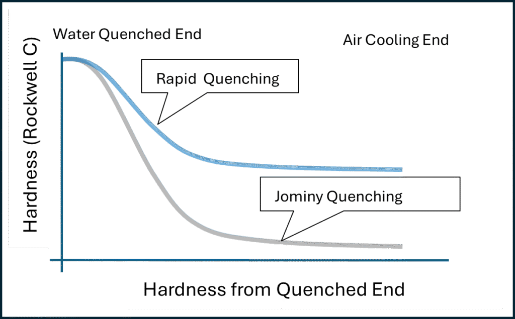
Today’s rapid quench technologies reveal a key limitation: the classic Jominy test can systematically underestimate what many steels are capable of under aggressive convective cooling. Why? Because film boiling — a vapor layer at the steel surface — chokes heat transfer right where it matters most.
In order to take advantage of a wider range of materials and processing methods, a shift in how to leverage this test is necessary. The discussion that follows elaborates on this American origin story of the Jominy’s test and what challenge the film boiling layer posed 75 years ago versus today.
Pursuing Performance: The Origins of the Jominy Test
In 1947, Fred P. Peters wrote in Scientific American that
hardenability
was no longer just a technical trend; it was a revolution changing how the steel industry did business. He was describing a shift in which clients wanted to move away from buying a grade based on chemistry specs alone to buying a product that would guarantee performance.
*Hardenability: the ability of a steel to harden to a certain depth. Hardness, by comparison, is the measurement of how hard a material is at a given location. High hardenability ensures desired properties and microstructure at a given depth for critical components; this leads to more efficient optimized part designs.
But there was a problem: Steelmaking was, and still is, a complex science with unavoidable variability arising from chemical, thermal, and metallurgical processes involved. From batch-to-batch, a single supplier could achieve different hardenability results. That variability caused headaches for manufacturers.
Two metallurgists working with General Motors, Walter Jominy and A.L. Boegehold, proposed an elegant solution: standardize the cooling conditions instead of chasing exact chemistry. Pinpointing the “maximum hardness at center” had been an estimate derived from submerging several steel bars of various diameters in a quench tank. Speaking to the Detroit Chapter of American Society of Metals, the metallurgists pushed for an end-quench test using a standardized one-inch round bar, heated uniformly, and quenched at one end with a water jet. Their practical solution replicated the range of cooling rates from the maximum cooling rate (water) at the quench face to the slowest cooling rate (air) at the other end of the bar. The resulting hardness profile became a “fingerprint” of that alloy’s hardenability.
That fingerprint changed everything.
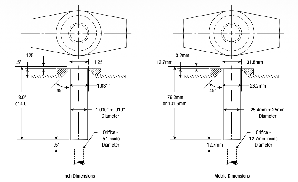
Figure 1. Diagram of the Jominy End-Quench Test | Reference: ASTM A255-02
Metallurgists could now rapidly compare alloys from different suppliers or with minor chemistry differences. Additionally, design engineers could specify hardenability bands rather than tight chemistry limits. Steelmakers could adjust compositions and quickly verify performance. Scrap heats dropped. Costs fell. Customers gained predictable, repeatable results. ASTM A255 formalized the method, and the Jominy test became the global language of hardenability (Figure 1).
Known Limitations and Rapid Quench
Heat treaters know the Jominy test is a simplification. The specimen is a straight bar, not a gear or forging. Only one end is quenched. The cooling method represents one type of quench: water, not oil, polymer, or gas.
There’s also a compositional limitation; highly alloyed steels often show little variation along the four-inch test length.
But one limitation has taken on new importance in modern heat treatment: the vapor blanket.
The Vapor Blanket Problem
When red-hot steel hits water, a vapor layer instantly forms on the surface. This “Leidenfrost layer” acts like insulation. Heat transfer drops until the vapor film collapses and nucleate boiling begins.
That means the cooling severity at the Jominy face is not just “water quench.” It is water quench through a steam barrier.
So, the hardenability curve we measure reflects steel transformation behavior plus a boiling-limited surface condition. If that vapor layer is removed or shortened, the cooling rate at the surface rises, and the steel may harden deeper than the standard Jominy curve suggests.
Over the past two decades, a new approach has gained traction: do not accept film boiling — remove it.
Researchers, such as Dr. Kobasko and Dr. Aronov, showed through modeling and experiments that high-velocity, high-pressure water flow can consistently suppress the vapor layer, a method known as Intensive Quenching™. This approach pushes the hot surface quickly into high heat transfer by removing the vapor film and has been referred to as High Convective Quenching, High-Pressure Convective Quenching, and Rapid Quenching.
The result is more than faster cooling.
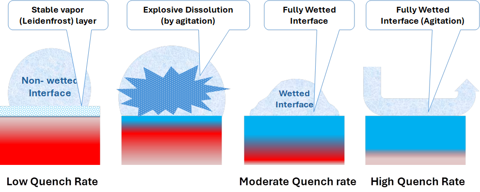
Figure 2. Quench rate and surface reactions
Early formation of a martensitic surface shell creates compressive stresses that enhance fatigue and wear resistance. Parts can show deeper effective hardening and improved surface performance without increasing alloy content (Figure 2). Some studies even suggest differences in martensite morphology (twinned morphology) compared to conventional quenching (lath morphology). This is not just “harder steel.” It is a different thermal-mechanical response at the surface.
Rethinking the Jominy Test
If quenching technology has changed, should the hardenability test evolve too?
Research at the University of Akron has shown that the standard Jominy setup itself forms a vapor layer. Raising the jet height does not eliminate it. That means the test measures hardenability under a boiling-limited condition, not under maximum achievable heat transfer.
Figure 3. Standard vs. Rapid Quench Hardenability | Image Credit: Gopal Nadkarni
Working with industry partners, the university researchers developed a modified end-quench configuration that uses high-convective water impingement to strip the vapor barrier. The measurement philosophy remains Jominy-based i.e. measure hardness along the length of the bar. What changes is that the end of the flat bar is given a slight taper to allow it tightly seal into a chamber where a water jet is sprayed on the surface, much like a jet pressure washer. Modeling this scenario allows us to predict that the new pressure and flow conditions are sufficient to strip the vapor and keep it from reforming, thus creating conditions of maximum heat transfer without the continuous formation of the film. The old “umbrella” method of cooling does not ensure the removal of the vapor or film on surface. The result is a new method that reveals how steels behave under rapid quench — conditions increasingly used in advanced heat treat operations (Figure 3).
Why This Matters to Industry Now
For 75 years, engineers have relied on handbooks filled with Jominy curve diagrams. Those curves remain valuable, but they reflect a quenching severity rooted in mid-20th-century practice.
Today, heat treaters, steelmakers, and designers have a chance to expand that framework. A rapid-quench Jominy approach could help:
Optimize alloy design for modern quench systems
Improve simulation accuracy in digital twins
Reduce over-alloying and cost
Increase part performance and consistency
This is not about redefining hardenability. It is about recognizing that hardenability is expressed under a defined cooling boundary. As quenching technology advances, our standardized ways of describing steel response should advance with it.
In Part 2, we’ll look at how this modified Jominy approach aligns with ASTM philosophy, what simulation reveals, and how rapid quenching translates into real improvements for gears, heavy components, and other critical parts.
About The Author:
Dr. Gopal Nadkarni Associate Professor of Mechanical Engineering University of Akron
Dr. Gopal Nadkarni is an Associate Professor of Mechanical Engineering at the University of Akron and manages its Manufacturing Graduate Certificate Program. He brings extensive industry and innovation experience, having held previous leadership roles at industry and in technology ventures, with research and teaching focused on manufacturing, materials, and product design.
To contribute to ongoing industry-academia research regarding this topic, please contact Professor Gopal Nadkarni.
Ask The Heat Treat Doctor® has returned to bring sage advice to Heat Treat Today readers and to answer your questions about heat treating, brazing, sintering, and other types of thermal treatments as well as questions on metallurgy, equipment, and process-related issues. In this installment, Dan Herring discusses practical strategies for managing distortion through oil quenching, focusing on how subtle adjustments — such as delaying agitation to extend the vapor blanket phase — can influence heat transfer behavior and improve dimensional stability in challenging geometries like thin-walled, large-diameter gears.
This informative piece was first released in Heat Treat Today’sApril 2026 Annual Induction Heating & Melting print edition.
The Question
A reader’s question caught the Doctor’s eye and will provide some valuable information we all can benefit from. Let’s learn more:
“I have a question about a technique we used sometimes in my factory for distortion reduction. As you know, in the oil quench cooling there are 3 steps: 1. Vapor Blanket Phase (≈ 840–700°C) 2. Boiling Phase (≈ 700–400°C) 3. Convection (≈ 400–40°C) In addition to [running] a martempering oil (Houghton M240) and a high oil temperature of 80–100°C, a technique we used successfully to reduce the distortion in thin wall large (> 1m) gears was to wait 1 minute without agitation just after placing the parts in the oil tank. Once the minute has passed, we start with the agitator speed at 1,700 rpm. The technical reason for this improvement is to extend the vapor blanket step and hence reduce the distortion created by the boiling step. My questions are: What effect does the vapor blanket step have on thermal uniformity, and is it possible to get a similar result in the agitator speed, for instance, start with a low rotating speed and finishing with a high speed?”
The Three Phases of Quenching
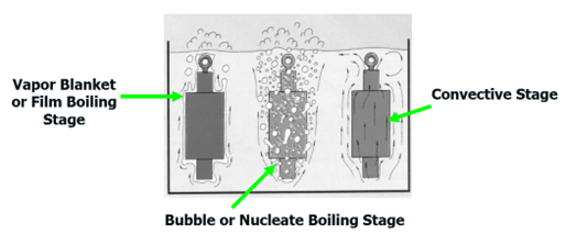
As a brief reminder, let’s revisit the three distinct stages of cooling (Figure 1). The first stage, the “vapor blanket” (or “film boiling”) stage, is characterized by the Leidenfrost phenomenon, which is the formation of an unbroken vapor blanket that surrounds and insulates the work piece. It forms when the supply of heat from the surface of the part exceeds the amount of heat that can be carried away by the cooling medium.
The stability of the vapor layer, and thus the ability of the oil to harden steel, is dependent on: the metal’s surface irregularities; oxides present; surface-wetting additives, which accelerate the breakdown and destabilize the vapor blanket; and the quench oil’s molecular composition, including the presence of more volatile oil degradation by-products (Herring 2015). In this stage, the cooling rate is relatively slow in that the vapor envelope acts as an insulator, and cooling is a function of conduction through the vapor envelope.
The second stage, the “vapor transport” (or “nucleate boiling” or “bubble boiling”) stage, is where the highest heat transfer rates are produced — and where the greatest amount of distortion occurs. The point at which this transition occurs and the rate of heat transfer in this region depend on the oil’s overall composition (base oil, speed accelerators, and antioxidant package). It begins when the surface temperature of the part has cooled enough so that the vapor envelope formed in the first stage collapses. Violent boiling of the quenching liquid results, and heat is removed from the metal at a very rapid rate, largely due to heat of vaporization. The boiling point of the quenchant determines the conclusion of this stage. Size and shape of the vapor (bubbles) are important in controlling the duration of this stage.
Figure 1. The three stages of liquid quenching | Image Credit: The Heat Treat Doctor®
The third stage of cooling is called the “convection” (or “liquid”) cooling stage. The cooling rate during this stage is slower than that developed in the second stage and is exponentially dependent on the oil’s viscosity, which will vary with the degree of oil decomposition. Heat transfer rates increase with lower viscosities and decrease with increasing viscosity. This final stage begins when the temperature of the metal surface is reduced to the boiling point (or boiling range) of the quenching liquid.
The Answer
A sage veteran once reminded the Doctor that we cannot control distortion, only manage it.
As we know, if we were able to control the heat transfer during the nucleate boiling phase, the result would be less gear distortion, especially when the geometry (in this case thin wall, large diameter gears) makes it even more challenging.
What many people do not realize is that in addition to the correct choice of oil, oil temperature, the proper size and design of the quench system (which is fixed for all part or load configurations), and the uniform removal of the vapor blanket in the first stage of quenching influences the development and type of heat transfer that will occur in the nucleate boiling phase — yes, it is uncontrolled, but it can be influenced.
A delay in the start of agitation ensures the vapor blanket phase is extended and (in a sense) more uniformly conforms to the part geometry than it would otherwise. The result is that it is easier to be uniformly swept away once the agitation begins. Interestingly, the vapor blanket begins to form within the first few seconds of quenching and begins to collapse (often in a nonuniform way) as the surface temperature drops. Agitation delay times ranging from 1 to 2 minutes have been used in industry, which are primarily a function of material, (gear) geometry, and tooth profile/thickness.
As to the other question, some manufacturers recommend quenching into slowly agitated oil (100–125 rpm) — the slower agitation only intended to push any moisture molecules around, then increasing the speed to normal agitation rates once the load is fully submerged. Appropriate safety precautions must be followed with either method. A great deal of success has been reported using this method for many of the same reasons as above.
On another note, there is some merit in vacuum oil quenching to vary the pressure over the oil. Interestingly, the characteristics (i.e., size and distribution) of the “bubbles” formed in the nucleate boiling phase changes and the end result is that they can be more easily and more uniformly swept away.
In Summary
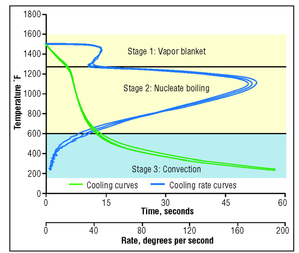
A word or two is in order about measuring and maintaining the quench oil. Measuring the efficiency (i.e., speed) of an oil can be done in one of two ways. The first method is by measuring the oil’s cooling ability (i.e., hardening power). Since cooling ability is independent of steel selection (composition and grain size) this method is popular since it provides information about the oil itself independent of its end use application (Figure 2).
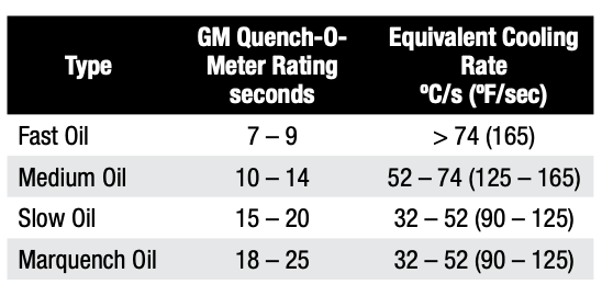
Figure 2. Typical cooling curves and cooling-rate curves for new oils | Image Credit: The Heat Treat Doctor®Table A. Classification of Quench Oils
The older GM Quench-O-Meter method (Table A) can be used as well.
Variables Affecting Dimensional Change
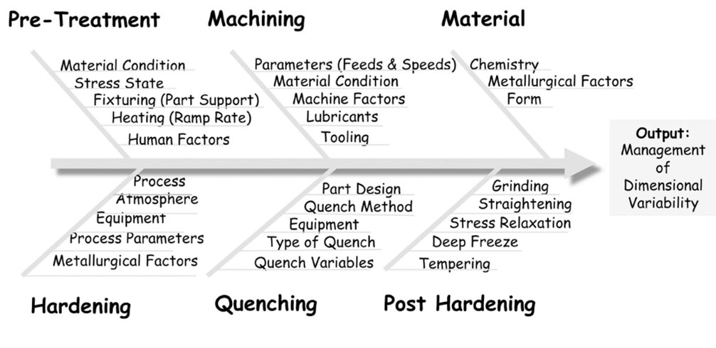
A number of factors influence post-heat treat distortion, including those related to material, manufacturing, and heat treating (Figure 3).
When selecting an oil quench process, some of the many factors to consider include:
Material — form, chemistry, hardenability, grain size, homogeneity, cleanliness, microstructure
Heat treatments performed at the mill
Starting microstructure — mill or third-party heat treating prior to manufacturing
Manufacturing process — sequence of operations, tooling, speeds & feeds
Part orientation during manufacturing, as opposed to grain orientation
Grids, baskets, and fixtures — both material & design
Load configuration — part spacing, orientation, arrangement (load density)
Load weight (gross or net)
Maximum quench fixture size, weight, shape
Part geometry and mass — maximum/minimum part section thickness, consideration for whether the component part is uniform in thickness or has thin and thick sections next to one another
Residual stress state before heat treatment
Targeted hardness range (initial or final)
Type of process being run (e.g., hardening, case hardening)
Free quenching or restricted (press or roll) quenching
Oil type — quenching characteristics, cooling curve data
Oil speed, condition, viscosity (fast, 7–9 second oil; medium, 10–14 second oil; slow, 15–18 second oil; or marquench, >20 second oil)
Oil temperature (initial, instantaneous rate of rise, recovery time to initial temperature)
(Effective) quench tank volume
Height of oil above the load
Agitation — agitators or pumps
Quench tank design factors
Agitation method and number of agitators or pumps
Type of quench tank baffling
Location/size of agitators or pumps
Type of agitators (e.g., fixed, two speed, variable)
Propeller size (e.g., diameter, clearance in draft tube)
Internal tank baffling (e.g., draft tubes, directional flow vanes)
Flow direction
Flow restrictions (quench elevator and baffling design)
Volume of oil
Maximum (design) temperature rise
Heat exchanger-type, size, heat removal rate (instantaneous and total demand)
Quench elevator design (e.g., hearth type, sidewalls, flow restrictions)
Flow velocity (with and without a load present)
Number of furnaces to be served by the quench system
Duty cycle (i.e., the frequency of quenching or time between quenches)
Post heat treatment operations, if applicable
Furnace temperature uniformity
Furnace repeatability
Type of furnace atmosphere
Post processing (e.g., washing, deep freeze or cryogenic treatment, number of tempers)
Time delay between heat treat operations (especially important for high hardenability materials to avoid cracking)
References
Herring, Daniel H. 2015. Atmosphere Heat Treatment. Volume 2, BNP Media II.
About the Author
Dan Herring “The Heat Treat Doctor” The HERRING GROUP, Inc.
Dan Herring has been in the industry for over 50 years and has gained vast experience in fields that include materials science, engineering, metallurgy, new product research, and many other areas. He is the author of six books and over 700 technical articles.
Vacuum furnaces performing hardening have been in use for over 50 years, yet many heat treaters may not be taking full advantage of newer, more advanced analysis tools and methods. Controlling the cooling pressure can dramatically improve toughness and tool life, but only if applied with precision. In this Technical Tuesday installment, Paulo Duarte, technical director at Treatnorte, explores the science behind gas quenching, the role of step cooling, and why measuring and adjusting cooling curves is critical for consistent, high-performance results.
This informative piece was first released in Heat Treat Today’sMarch 2026 Annual Aerospace Heat Treating print edition.
Introduction
It has been a long time since the invention of the vacuum hardening process, yet innovation in this field continues. In recent years, industrial furnaces capable of operating with higher cooling gas pressures — up to 15 bar now commonly offered on the market — have become standard. But do we truly know how to make the best use of such high pressures?
Pressures up to 10 bar were first applied to cool small parts made from cold-work tool steels, such as sheet metal stamping tools. However, such high pressures can lead to cracking in larger hot-work steel dies when cooled directly. Step cooling was introduced as a solution: start with a fast initial cooling at higher temperatures to avoid carbide formation, then gradually lower pressure stages during the final cooling phase to reduce distortion and minimize the risk of crack appearance.
Despite this empirical knowledge, the question remains: do we really understand what we are doing? Are we routinely measuring cooling rates to determine where they stand on the CCT diagram, predicting microstructure and properties, and adjusting quenching parameters accordingly? And are we certain about which pressures to use for producing high-performance, demanding tools?
Cooling in Vacuum Furnaces
Quenching is one of the most critical steps in the hardening cycle. It transforms austenite into the optimal final microstructure, avoiding the formation of coarse carbides and pearlitic constituents during cooling. This ensures the finest possible microstructure.
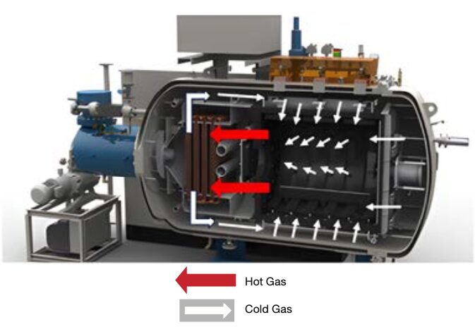
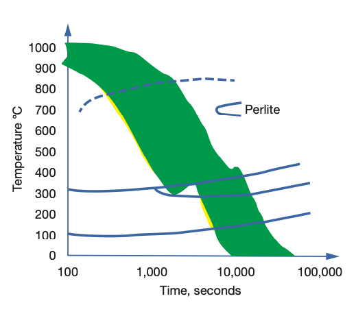
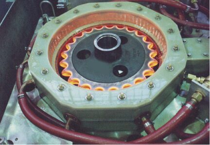
Figure 1. Gas quenching in a vacuum hardening furnace | Image Credit: SECO/WARWICKFigure 2. Surface cooling rates region on systematic analysis of parts quenching in a 600 mm x 600 mm x 900 mm furnace. Parts comprising weights from 500 up to 1,000 kg. Cooling pressures varies from 4 to 5 bar. Hot work tool steel. | Image Credit: Metaltec Solutions
In vacuum furnaces, this is typically achieved by injecting cooling gas through nozzles directed at the surface of the parts located in the furnace hot zone. During cooling, the gas circulates through the chamber, being drawn through furnace ports into contact with the heat exchanger tubes. A turbine then blows the cooled gas back into the hot zone where the load is located (Figure 1).
The higher the programmed cooling pressure, the greater the volume of gas passing through the nozzles over the same period of time. This increases the heat transfer from the parts to the cooling gas, resulting in a faster cooling rate.
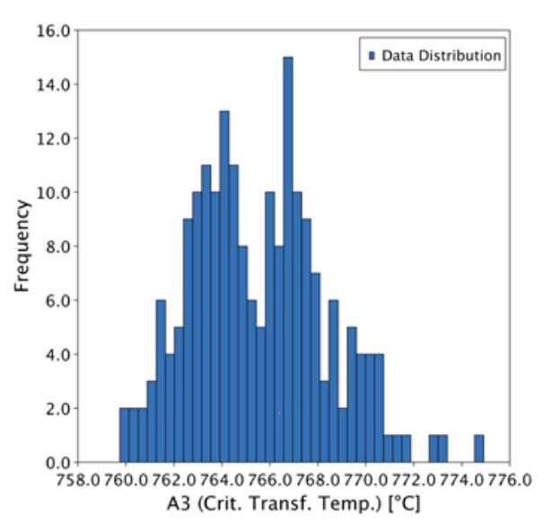
By measuring successive cooling curves for different loads, specifically for single hot-work steel tools weighing over 500 kg, surface cooling rates pass through the bainitic–martensitic domain (the green area of the CCT diagram shown in Figure 2). Thinner parts tend to cool closer to the martensitic end at the Ms-Bs intersection, while larger tools tend to approach the pearlitic nose.
These observations highlight the importance of adjusting cooling pressure to produce the desired microstructure and account for the different cooling behaviors of large, medium, and small parts.
Investigative Approach: Testing Furnace Data Against CCT Diagrams
Measuring part temperatures during cooling began over 20 years ago, using thermocouples and data loggers, and comparing the results to steel continuous cooling transformation (CCT) diagrams. Most vacuum furnaces do not include this capability as standard, and when available as optional software, many companies choose not to invest in it. In 2005, it was discovered what few in the industry knew at the time: hardening hot-work tool steels in industrial vacuum furnaces often results in a bainitic–martensitic microstructure. This phenomenon is now more widely recognized, with published cooling curves overlaid on CCT diagrams for larger tools becoming more available.
Even so, open discussion remains rare, partly because many heat treaters are reluctant to present this evidence to academia, fearing criticism that their results do not match the fully martensitic microstructure taught at universities. This is not a debate about right or wrong, but rather an opportunity for research and improvement in heat treatment practices worldwide.
After initial testing with a 600 mm × 600 mm × 900 mm French-made single-chamber furnace, trials continued with a larger 900 mm × 900 mm × 1,800 mm German-made vacuum furnace. These tests began by measuring both surface and core temperatures for repeated cycles with small and large charges ranging from small cold-work tools to hot-work tool steel parts weighing 500–1,500 kg. Leading vacuum furnace manufacturers in North America and Europe have developed technologies capable of successfully heat treating small, medium, and large tools, resulting in microstructures that often contain both bainite and martensite. This is, in fact, an inherent characteristic of the technology. Such tools have performed well in service for decades. That said, heat treaters using higher cooling pressures have seen improved tool life significantly, while also increasing the risk of treatment failures if the pressure is too high.
In the last 10 years, properties and microstructure analyses have shown that variations in cooling rate can significantly change the microstructure and toughness of the part even within the same bainitic–martensitic domain of the CCT diagram.
With the emergence of Industry 4.0 and 5.0, along with digitalization and AI, systematic research into heat treatment processes combined with quenching deformation simulation can lead to better selection of cooling pressures. This is a critical parameter in controlling the hardening process, and it has a direct impact on part toughness and service performance. Metaltec Solutions introduced one of the first software tools aimed at improving vacuum heat treatment through Industry 4.0 concepts in 2017. This technology represents a step toward greater awareness and precision in tool steel hardening, helping heat treaters program their cycles for optimal performance in demanding applications.
Regulating Pressure in Vacuum Hardening Furnaces
To obtain the best possible microstructures, gas quenching must be programmed in the furnace so that the cooling rate is kept as close as possible to the martensitic end, i.e., at the Ms-Bs intersection, of the CCT diagram, avoiding the formation of coarse and undesirable microconstituents in the steel. This is achieved by selecting the highest permissible cooling pressure that still prevents cracking or excessive deformation. While small parts can withstand direct high-pressure cooling, larger tools require a reduction in cooling pressure.
Preliminary Pressure Comparison
For optimal quenching of large parts, the cooling pressure should not remain constant throughout the entire cooling cycle. Instead, high pressure should be applied during the initial cooling stage to prevent coarse carbides and pearlite formation and then reduced when the surface temperature reaches approximately 550°C (1022°F). This creates a martempering stage at lower pressures, reducing the risk of distortion and cracking.
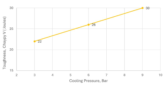
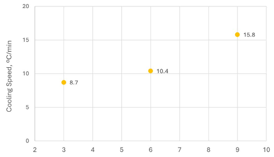
Figure 3a. Cooling pressure effect on Vidar Superior (an H11 steel grade variation) part surface toughness | Image Credit: Metaltec SolutionsFigure 3b. Cooling pressure effect on 400 mm x 400 mm x 400 mm block surface toughness | Image Credit: Metaltec Solutions
If we measure the toughness of steel pieces quenched at different cooling pressures, then tempered together to achieve a typical 46–48 HRC hardness (in hot work tool steel), we find that higher cooling pressures result in greater toughness. Using older furnace pressures (around 3 bar) yields lower toughness, whereas increasing cooling pressure can improve toughness by approximately 60% (Figure 3a). This translates into longer tool life, since high-pressure-quenched tools better absorb stress, delaying the initiation and propagation of cracks. These benefits result from higher cooling rates (Figure 3b) and the corresponding finer microstructures achieved.
Although quenching at 3, 6, and 9 bar passes through the same transformation domain on the CCT curve, differences in the resulting internal steel structure, whether coarser or finer, are clearly observable.
True Toughness and Speed
Looking in more detail at the above findings, we can observe that when parts are cooled in a 900 mm × 900 mm × 1,800 mm vacuum furnace, the gas temperature drops below the Ms temperature (for typical hot work tool steels) in less than one minute. The gas temperature then remains near room temperature during the subsequent cooling of the parts (Figure 4a).
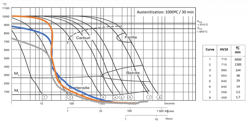
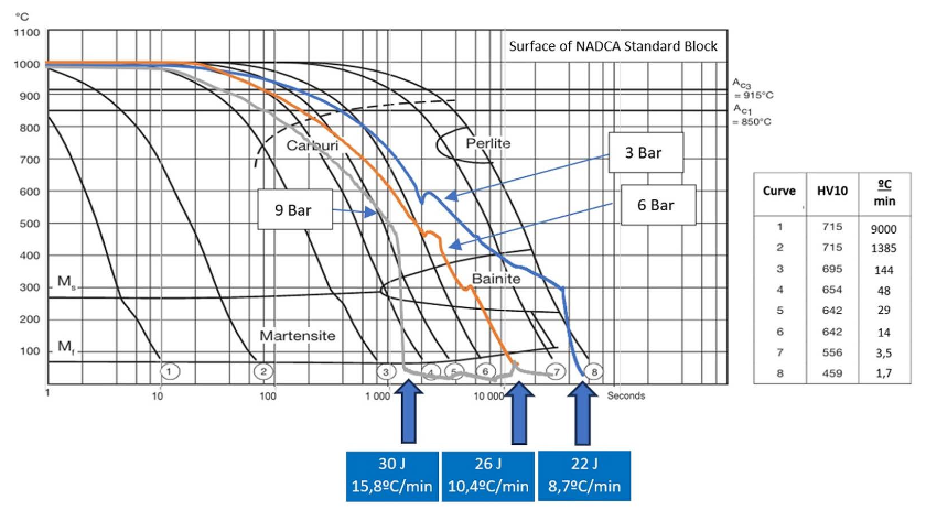
Figure 4a. Cooling NADCA block in a large vacuum hardening furnace; gas cooling rate according to gas pressure used | Image Credit: Metaltec SolutionsFigure 4b. Cooling NADCA block in a large vacuum hardening furnace; surface cooling curves and its respective toughness after tempering, with the alteration of the cooling curve behavior provided by the martempering (final hardness level 46–48HRC hot work tool steel | Image Credit: Metaltec Solutions
The parts, however, take considerably longer to cool down to the furnace unloading temperature, depending on the cooling pressure applied. When analyzing the cooling of large dies using the NADCA block as the standard size for comparison, the surface cooling curves vary according to the applied pressure, falling into the bainitic–martensitic domain for 3, 6, and 9 bar cooling pressures.
From this data, it can be seen that hardness is not significantly affected by using 3, 6, or 9 bar cooling pressures, even though the higher pressures produce cooling rates up to twice as fast as the slower ones. Toughness, however, is largely influenced by the way the cooling curves pass through the bainitic–martensitic domain, whether crossing the Bs and Ms intersection closer to the martensitic end (9 bar), near the center (6 bar), or closer to the pearlitic nose (3 bar).
Tuning Pressure and Time
These results show that, within the typical cooling rates of vacuum hardening (Figure 2), toughness varies significantly with cooling pressure, corresponding to finely tuned cooling speeds ranging from approximately 9 to 16°C/min (48 to 61°F/min) between 800°C and 500°C (932°F and 1472°F). This highlights the need to use the highest possible cooling pressures to achieve excellent properties while avoiding direct high-pressure cooling of large parts by applying step cooling with an initial fast cooling phase, followed by reduced pressure.
How Microstructure Drives Toughness
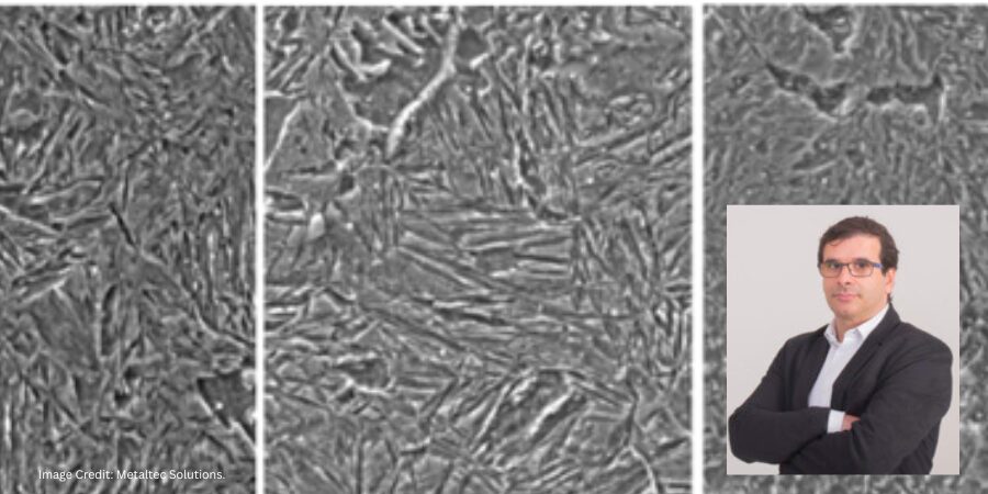
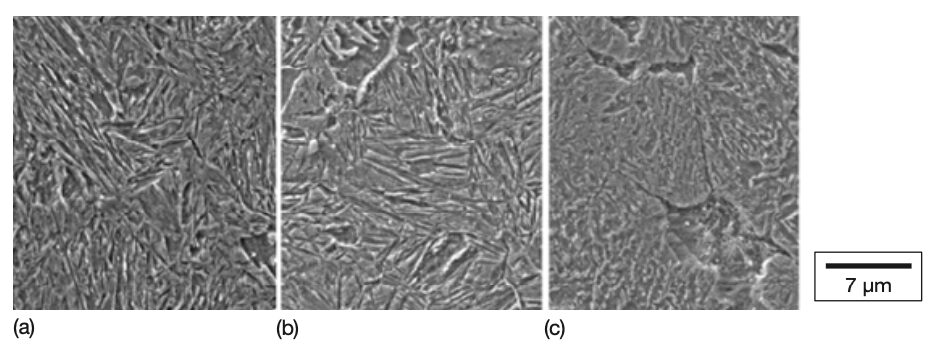
The reason for achieving better properties at higher cooling pressures lies in the resulting microstructure, as shown in Figure 5. Fine bainite and martensitic needles, formed through faster cooling rates, are responsible for the higher toughness observed. When lower cooling pressures are used, the cooling rate decreases, leading to coarser needle sizes (Figres 5a–c) and, consequently, lower toughness values.
Figure 5a-c. Microstructures obtained after quenching Orvar Supreme (premium H13 steel): a) 100°C/min; b) 12°C/min; c) 3°C/min (or, a) 180°F/min; b) 22°F/min; c) 5°F/min) | Image Credit: Metaltec SolutionsFigure 6. Toughness model | Image Credit: Metaltec Solutions
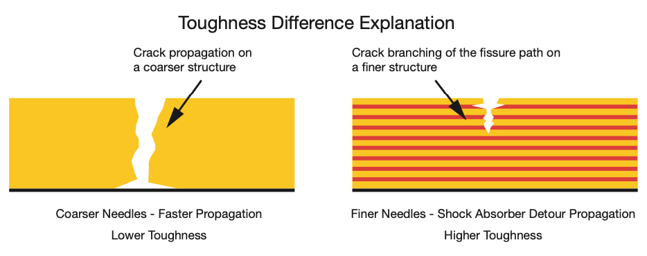
This can be explained by Figure 6. In a coarser microstructure, cracks can propagate more easily because there are fewer obstacles to their advance. In finer microstructures, the higher density of needles forces cracks to deviate repeatedly from their path due to the branching effect, altering the directions of crack propagation. This “shock absorber” effect — caused by the frequent detours a crack experiences when traveling through a greater number of fine needles — is the reason for the toughness improvement observed when higher cooling pressures are used to achieve faster cooling rates.
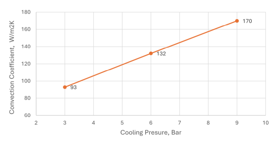
Figure 7. Convection coefficients for a 900 mm × 900 mm × 1,800 mm vacuum hardening furnace according to the pressure being used | Image Credit: Metaltec Solutions
Each furnace behaves differently, from one furnace builder to another and also depending on the level of maintenance of a furnace. So a similar furnace to the one used for obtaining cooling curves and corresponding toughness values (Figure 4b) was used to obtain the convection coefficients (Figure 7). We can see a strong correlation between convection coefficient, pressure, and final toughness obtained, indicating that these features must be carefully adjusted to reach optimal part properties and longer service life.
Conclusion
Properly applying cooling pressures, through direct high-pressure cooling for small loads or step cooling for larger tools, can significantly increase part toughness and extend tool life. The key lies in understanding how cooling curves interact with the bainitic–martensitic microstructure and adjusting pressure according to part size, geometry, and furnace characteristics.
By measuring temperatures, analyzing microstructures, and fine-tuning cooling cycles, heat treat operators can achieve consistent, high-performance results, as demonstrated with the above studies on tool steels. Faster, well-controlled cooling typically produces finer bainitic–martensitic microstructures which results in a part with “shock absorber” qualities.
Ultimately, maximizing cooling pressure, not just for minimal distortion, creates more durable tools, reduces downtime, and strengthens competitiveness through part performance.
About The Author:
Paulo Duarte Technical Director Treatnorte
Paulo Duarte is an independent researcher and consultant on heat treat technologies, also working as technical director at Treatnorte. His education and expertise in metallurgy have culminated in several articles and patents. Previously, he was the project manager at Metalsolvus and also had been the technical manager and heat treatment manager within bohler-uddeholm group for the Portuguese market. Currently, Paulo focuses on helping heat treaters by providing innovative, more efficient, and profitable heat treatment services to companies.
Ask The Heat Treat Doctor® has returned to bring sage advice to Heat Treat Today readers and to answer your questions about heat treating, brazing, sintering, and other types of thermal treatments as well as questions on metallurgy, equipment, and process-related issues. In this installment, Dan Herring continues his discussion on gear heat treatment, exploring vacuum and induction hardening methods for gears — from low-pressure carburizing for advanced materials to single shot and tooth-by-tooth induction techniques — and how each can be matched to the specific demands of any gear application.
This informative piece was first released in Heat Treat Today’sMarch 2026 Annual Aerospace Heat Treating print edition.
In Part One of this discussion (Air & Atmospheres Heat Treating, February 2026), we discussed various gear types, materials, and how they can be atmosphere heat treated. This month, we are focusing on vacuum and induction heat treating methods. Let’s learn more.
Vacuum Heat Treatment Processing Methods
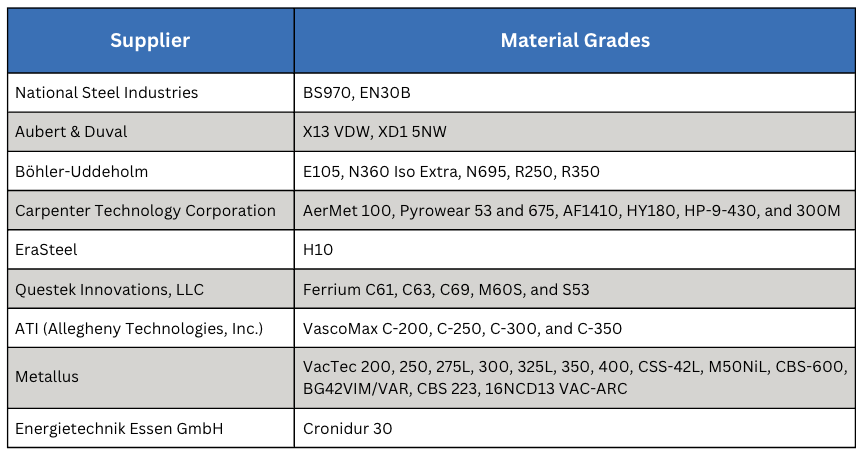
Table A. Advanced Materials Processed by LPC
Vacuum processing can be used for most of the atmosphere treatments mentioned in Part One including carburizing (Figure 1). Low pressure carburizing (LPC) is a proven technology and the choice for many advanced applications in aerospace, automotive, off-highway, and motorsports markets, as well as the development of carburizing cycles for high-performance materials (Table A).
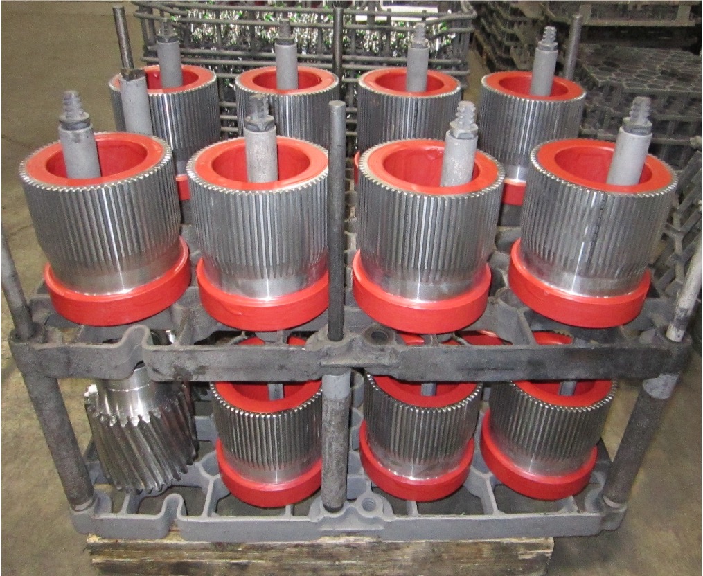
Figure 1. Typical commercial heat treat load of gears for vacuum carburizing (Otto and Herring 2007) | Image Credit: Photo courtesy of Midwest Thermal-VacFigure 2. Pyrowear 675 – LPC – anneal – double normalize – harden – anneal – deep freeze – double temper | Image Credit: The HERRING GROUP, Inc.
The range of effective case depths for most of these grades can range up to 2.0–3.0 mm (0.080–0.120 inches) without significant sacrifice of microstructure (Figure 2). Furnace variables, such as temperature uniformity (± 3°C or ± 5°F), control of cycle parameters (boost/diffuse times, gas flow rate, pressure, hydrocarbon type) and surface carbon optimize the microstructure, producing case uniformities of ± 0.05 mm (± 0.002 inches). Where permitted, the range of carburizing temperatures now includes the use of high temperature (> 980°C, or 1800°F) techniques.
All these advanced materials required extensive development testing to produce custom designed recipes to optimize cycle parameters. Also, quenching methods (Otto and Herring 2002) have improved, allowing us to achieve desired core properties with quenching parameter selection (high-pressure gas or oil) for distortion-sensitive and distortion-prone part geometries (Otto and Herring 2005, 2008).
Induction Hardening Methods
Various methods of hardening via applied energy are used in manufacturing gears, including flame hardening, laser surface hardening, and induction hardening.
Of the various types of applied energy processing, induction hardening is the most common. Induction heating is a process that uses alternating electrical current that induces a magnetic field, causing the surface of the gear teeth to heat. The area is then quenched resulting in an increase in hardness within the heated area. This process is typically accomplished in a relatively short time. The final desired gear performance characteristics are determined not only by the hardness profile and stresses but also by the steel composition and prior microstructure. External spur and helical gears, bevel and worm gears, racks, and sprockets are commonly induction hardened. Typical gear steels include AISI/SAE grades 1050, 1060, 1144, 4140, 4150, 4350, 5150, and 8650.
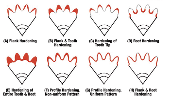
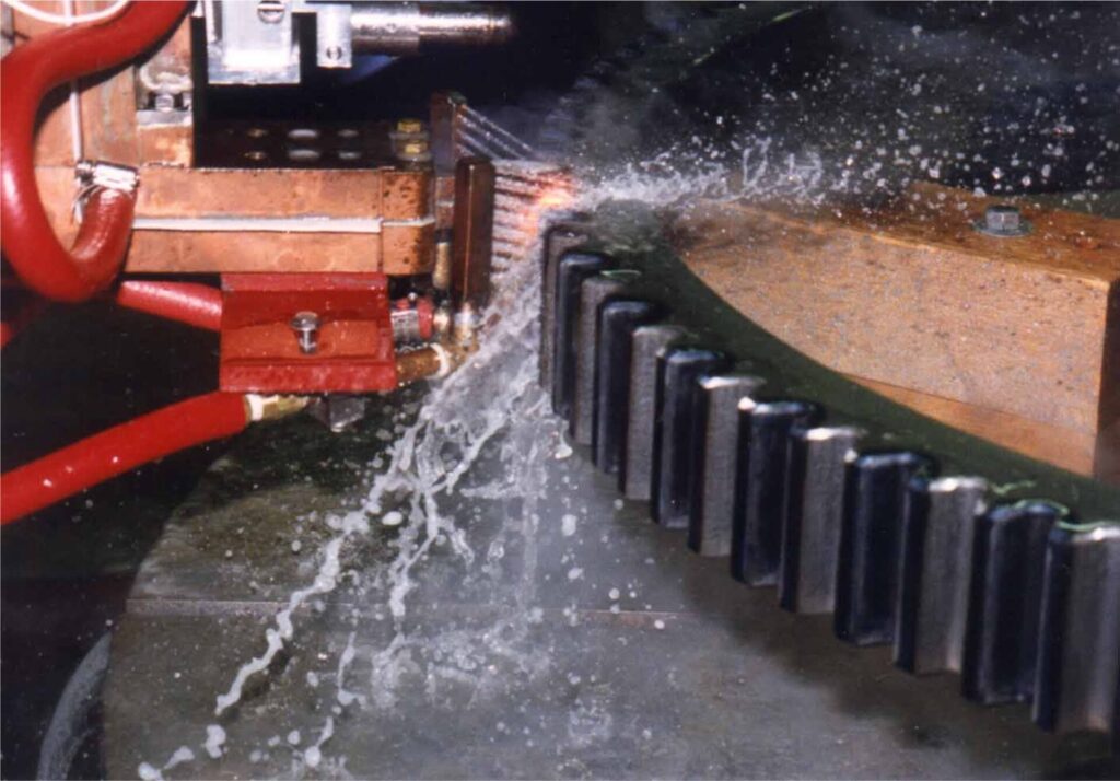
Figure 3. Patterns produced by induction hardening (Rudnev 2000)
The hardness pattern produced by induction heating (Figure 3) is a function of the type and shape of inductor used, as well as the heating method. Quenching or rapidly cooling the workpiece can be accomplished by spray or submerged quench. The media typically used for the quench is a water-based polymer. The severity of this quenchant can be controlled by the polymer’s concentration. Cooling rates are usually somewhere in between what would be obtained from pure water and oil. In some unusual situations compressed air or nitrogen is used to quench the part.
The most common methods for hardening gears and sprockets are by single shot (Figure 4) or the tooth-by-tooth method (Figure 5). Single shot often requires large kW power supplies but results in short heat/quench times and higher production rates. This technique uses a circumferential copper inductor, which will harden the teeth from the tips downward.
Figure 4. Typical single shot induction hardening operation | Image Credit: Photo courtesy of Ajax-Tocco-MagnethermicFigure 5. Tooth-by-tooth induction hardening of a helical gear | Image Credit: Photo courtesy of Ajax-Tocco-Magnethermic
The larger and heavier loaded gears (where pitting, spalling, tooth fatigue, and endurance are issues) need a hardness pattern that is more profiled like those produced by carburizing, which can be obtained by tooth-by-tooth hardening. This method is limited to gear tooth sizes with modulus 4.23–5.08 (6 or 5 DP) using frequencies from 2 to 10 kHz and about 2.54 (10 DP) using a range of 25 to 50 kHz.
The lower the frequency, the deeper the case depth. Tooth-by-tooth hardening is a slow process and usually reserved for gears and sprockets that are too large to single shot due to power constraints. The process involves heating the root area and side flanks simultaneously, while cooling each side of the adjacent tooth to prevent temper-back on the backside of each tooth. The induction system moves the coil at a pre-programmed rate along the length of the gear. The coil progressively heats the entire length of the gear segment while a quench follower immediately cools the previously heated area. The distance from the coil to the tooth is known as coupling or air gap. Any changes in this distance can yield variation in case depth, hardness, and tooth distortion. The gear is indexed after each tooth has been hardened, often skipping a tooth. This requires at least two full revolutions in the process to complete the hardening of all teeth. Straight, spur, and helical gears up to 5.5 m (210 inches) weighing 6,800 kg (15,000 lb) have been processed with this method. The entire process yields a repeatable soft tip of the tooth with hard root and flank. In other applications, the tip and both flanks can be hardened simultaneously and yield a soft root.
In Summary
Today’s design engineer has the good fortune of being able to choose from a number of heat treatment technologies for any given type of gear material and design. When selecting a gear hardening method, it is essential to specify not only the desired mechanical and metallurgical properties, but the critical dimensions that must be held and even the desired stress state of the gears themselves. The secret to success is understanding the advantages and limitations of each technology and taking these into consideration when determining the overall cost of gear manufacturing.
References
Herring, Daniel H. 2004a. “Gear Heat Treatment: The Influence of Materials and Geometry.” Gear Technology, March/April.
Herring, Daniel H. 2004b. “Reducing Distortion in Heat-Treated Gears.” Gear Solutions, June.
Herring, Daniel H. 2007a. “Oil Quenching Technologies for Gears.” With Steven D. Balme. Gear Solutions, July.
Herring, Daniel H. 2007b. “Heat Treating Heavy Duty Gears.” With Gerald D. Lindell. Gear Solutions, October.
Herring, Daniel H. 2012–2016. Vacuum Heat Treatment. Vols. 1–2. BNP Media Group.
Herring, Daniel H. 2014–2015. Atmosphere Heat Treatment. Vols. 1–2. BNP Media Group.
Herring, Daniel H., Gerald D. Lindell, D. J. Breuer, and B. Matlock. 2001. “Atmosphere vs. Vacuum Carburizing.” Heat Treating Progress, November.
Herring, Daniel H., Gerald D. Lindell, D. J. Breuer, and B. Matlock. 2002. “An Evaluation of Atmosphere and Vacuum Carburizing Methods for the Heat Treatment of Gears.” In Off-Highway Conference Proceedings. SAE International.
Otto, Frederick J., and Daniel H. Herring. 2002a. “Gear Heat Treatment: Today and Tomorrow, Part 1.” Heat Treating Progress, June.
Otto, Frederick J., and Daniel H. Herring. 2002b. “Gear Heat Treatment: Today and Tomorrow, Part 2.” Heat Treating Progress, July/August.
Otto, Frederick J., and Daniel H. Herring. 2005. “Vacuum Carburizing of Aerospace and Automotive Materials.” Heat Treating Progress, January/February.
Otto, Frederick J., and Daniel H. Herring. 2007. “Advancements in Precision Carburizing of Aerospace and Motorsports Materials.” Heat Treating Progress, May/June.
Otto, Frederick J., and Daniel H. Herring. 2008. “Improvements in Dimensional Control of Heat Treated Gears.” Gear Solutions, June.
Rudnev, V. 2000. “Gear Heat Treating by Induction.” Gear Technology, March/April.
About the Author
Dan Herring “The Heat Treat Doctor” The HERRING GROUP, Inc.
Dan Herring has been in the industry for over 50 years and has gained vast experience in fields that include materials science, engineering, metallurgy, new product research, and many other areas. He is the author of six books and over 700 technical articles.
When a load hangs up during quenching, seconds matter and improvised decisions can escalate risk. In this Technical Tuesday installment, Bruno Scomazzon, general manager of Precision Heat Treat Ltd., outlines a step-by-step emergency response procedure for exactly this scenario, which is one of the most dangerous in atmosphere heat treating. Drawing on real-world experience, this guide is intended to help companies develop their own effective procedures for maintaining safety, controlling furnace conditions, and coordinating with emergency responders in high-risk situations.
This informative piece was first released in Heat Treat Today’sFebruary 2026 Annual Air & Atmosphere Heat Treating print edition.
If you have comments or questions about this article, please let us know at: editor@heattreattoday.com
A load has been transferred to the quench and the elevator is lowering into the oil, but the load becomes hung up and fails to fully submerge. The inner door successfully closes, and the outer (front) door remains closed.
This is an extremely high-risk situation requiring strict adherence to emergency procedures. The goal is to protect: first the personnel (minimize the chance of injury or escalation of the situation), then the facility, and finally the equipment.
1. Immediate Actions
DO NOT Open Outer Door
There may be a natural urge to assess the situation but resist temptation. DO NOT stand in front of or directly beside the outer door and never open it during an active hang-up. Opening this door can introduce oxygen to a hot chamber, causing:
Explosions or flash fires.
Loss of containment due to door warping or mechanical failure.
In extreme cases, the outer door may be compromised (blown off, stuck open, or partially open) with visible flames. This warrants immediate escalation to the fire department.
If Outer Door Cannot Be Closed
In this scenario, immediately notify the fire department and advise them to prepare for a foam response. DO NOT allow the use of water. This may trigger violent reactions with oil or atmosphere and spread the fire!
Internal trained responders should:
Don PPE.
Retrieve fire suppression gear.
Be ready to protect critical systems until responders arrive.
DO NOT shut down the furnace.
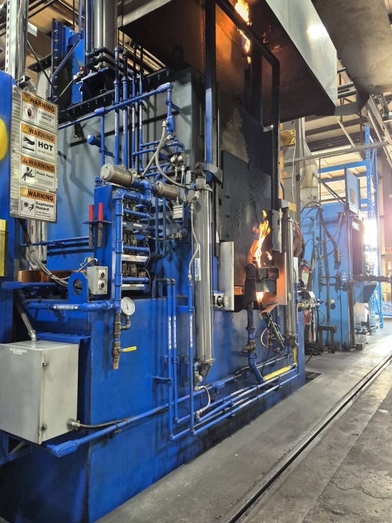
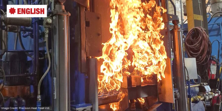
Figure 1. Atmosphere furnace during normal operation | Image Credit: Precision Heat Treat Ltd.Figure 2. Vestibule door partially opened during a controlled simulation to illustrate gas release behavior — not an actual incident | Image Credit: Precision Heat Treat Ltd.
2. Maintain Electrical Power
To ensure essential systems stay active, you must maintain electrical power. Ensure these systems stay active:
Set the furnace cycle to manual mode from auto mode. This will bypass any PLC sequencing from auto cycling doors, elevators, and handlers.
Keep the pilots lit.
Keep the oil cooler running to prevent tank overheating.
Shut off oil heaters to prevent additional heat loading in the quench tank.
Keep quench agitation on low during the entire period to assist in lowering the temperature at the interface surface area between the hot load and the oil. This prevents stratification and dissipates radiant heat into the oil.
Keep the recirculating fan running.
Keep the instrumentation functioning for monitoring.
NOTE: Loss of these systems eliminates visibility, atmosphere control, and safe response options.
3. Atmosphere Management
Maintain a protective atmosphere and positive furnace pressure to prevent oxygen ingress and uncontrolled combustion:
Set the carbon control to “0”.
Shut off the enriching gas.
Shut off the ammonia.
Shut off the dilution air.
Nitrogen Purge
These steps depend on whether a nitrogen purge is available; it is highly advised that nitrogen purge be available for all IQ or straight through units. Be sure you understand how long it takes for your specific furnace to fully purge endothermic gas. While NFPA 86 recommends five volume turnovers, some experts advise planning for up to ten per hour in an emergency. Each furnace should have established purge data under normal conditions so operators can act with confidence when time is critical.
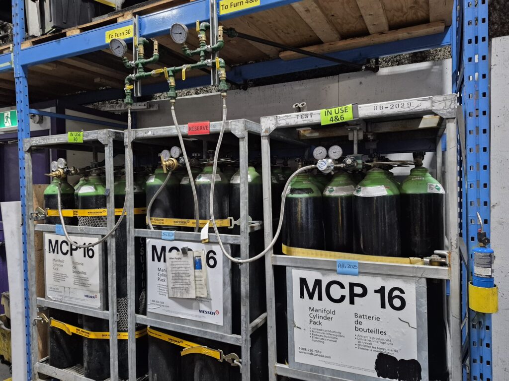
Figure 3. Bulk nitrogen supply used for emergency purging and atmosphere control | Image Credit: Precision Heat Treat Ltd.
Begin a nitrogen purge immediately (if available) and maintain it throughout the event.
Use at least the minimum flow rate specified in your documentation. If safe, higher flow may be used to help displace flammable gases from the heating and quench chambers.
Maintain furnace temperature at 1500°F during the purge.
Residual pockets of Endo gas may remain trapped in less ventilated areas. If the chamber temperature drops below the ignition point before all flammable gas has been displaced, the introduction of oxygen could trigger an explosion. In some cases, trapped Endo and pressure imbalances can lead to sudden releases (“furnace burp”), where oil or gas is expelled due to internal pressure buildup.
After the Purge
The goal of the nitrogen purge is to displace Endothermic gas with an inert atmosphere while maintaining elevated temperature to assist in burning off residual flammable gases and preventing dangerous mixtures. This process must ensure positive pressure throughout the furnace.
A purge followed by plunge cooling in nitrogen is a valid approach if the purge is verifiably complete.
Depending on furnace size and cooling rate:
Larger furnaces may cool slowly enough for a complete purge.
Smaller or faster-cooling units may require a brief temperature hold before controlled cooling or plunge cooling.
NOTE: Once the hung-up load cools to a safe temperature (~150°F), perform a standard shutdown.
Without Nitrogen (in Endo)
If there is no nitrogen purge, or it is insufficient, the only option is to let the hung-up load cool in the vestibule while continuing to burn Endo and maintain the furnace temperature at 1500°F. Once the vestibule/oil tank cools below 150°F and the danger has passed, initiate a standard furnace shutdown.
4. Safety Management
Alert the local fire department immediately. If the situation becomes unmanageable, or if there is any doubt about the ability to maintain control, evacuate the facility and wait for trained professionals. The safety of plant personnel is paramount.
Notify plant safety and site management.
Evacuate all non-essential personnel from the heat treat area.
Inform all departments that a high-risk incident is in progress.
Fire departments are most effective when they are familiar with your facility before an emergency occurs. Make sure they know the layout of your operation, including:
Oil tank locations and sizes
Electrical panels
Gas shutoffs
Hot zones
5. Controlled Cooling Period
Maintain atmosphere protection throughout the event.
DO NOT open doors until the vestibule’s temperature is low and stable.
Cooling time will depend on load mass and heat retention. Expect five or more hours.
Use furnace pressure stability, effluent observations, and gas behavior as indirect temperature indicators.
6. Load Recovery Procedure
Once cooled and stabilized, perform a standard shutdown, starting with the removal of endothermic gas if applicable.
DO NOT attempt manual load removal until the system is verified safe.
Only maintenance personnel may retrieve the load, using PPE and appropriate tools.
7. Fire Department Familiarization
Every facility should build rapport with the local fire department before an emergency ever happens. Schedule annual walkthroughs and identify the following:
Number of furnaces
Quench oil tank volumes
Hot zone and live panel locations
Emergency shutoff points
Stuck doors are commonly caused by failed pneumatic valves. Shutting off and bleeding compressed air may allow the mechanism to reset. Always consult your equipment manual or the manufacturer before attempting corrective action.
The fire inspector conducting walkthroughs is not the one coming to fight your fires — train the ones who are.
8. Post-Incident Protocol
Before returning the furnace to service:
Conduct a formal investigation.
Identify and correct root cause(s).
Document all key parameters and actions taken.
Re-train operators as needed.
Furnace Signage
An operator is likely to read your safety plan but may forget a vital protocol during an emergency. Having bold, brightly colored warnings printed and posted at the panel that the operator can remove and use in an emergency can be invaluable.
Final Reflections
We cannot predict every consequence. No procedure can account for every possible variable in a live emergency. Once an event is in motion, all we can do is respond with the best judgment, training, and intentions — always with the safety of people as the highest priority.
This document is intended as a working reference: a structured reference developed with care, real-world experience, and best practices. It is not a one-size-fits-all solution, but a tool to help teams create or enhance their own effective procedures and respond adaptively in high-risk situations.
Fire preparedness is essential in every heat treating facility. Fires happen, and they are not always small. It is critical to know when to act, when to evacuate, and when to call for help. Equipment manuals provide a foundation, but preparedness through training and planning is the best defense.
Acknowledgments: The author would like to thank Daniel H. Herring, “The Heat Treat Doctor,” The HERRING GROUP, Inc., and Avery Bell with Service Heat Treat in Milwaukee for their valuable input.
About The Author:
Bruno Scomazzon General Manager Precision Heat Treat Ltd.
Bruno Scomazzon is the general manager of Precision Heat Treat Ltd. in Surrey, British Columbia, Canada, with over 40 years of experience in metallurgical processes and heat treating operations.
Un austenizado insuficiente afecta mucho más que la dureza final. Interrumpe la transformación de fase, debilita el rendimiento mecánico y aumenta el riesgo de deformación o fallo en condiciones de servicio exigentes. En esta entrega de Technical Tuesday, Ana Laura Hernández Sustaita, fundadora de Consultoría Carnegie, explica los orígenes metalúrgicos de la formación incompleta de la austenita; como la uniformidad del horno, la velocidad calentamiento, la composición química del acero y la geometría de la pieza, contribuyen a ese problema; y las estrategias modernas de control de procesos y simulación que garantizan una transformación completa y resultados repetibles de alta calidad.
Este artículo informativo se publicó por primera vez enHeat Treat Today’sJanuary 2026 Annual Technologies To Watch print edition.
En inglés, el término underhardening se utiliza para describir aceros que no alcanzan una austenización completa, lo que se traduce en una pérdida de dureza después del temple. Sin embargo, en este artículo ampliaremos el análisis más allá de la dureza, centrándonos en el fenómeno de la austenización insuficiente, analizando sus causas, su influencia directa en la microestructura y en las propiedades mecánicas, así como las acciones que podemos implementar en el proceso para prevenirla.
El rol del proceso de austenización
El objetivo principal del tratamiento térmico es obtener una microestructura homogénea o mixta que garantice las propiedades mecánicas requeridas para las condiciones de servicio establecidas: resistencia a la tracción, resistencia al impacto, límite elástico, entre otras.
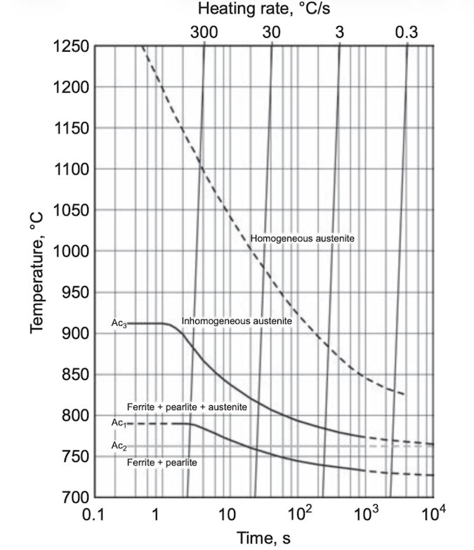
El proceso de austenización es el primer paso crítico para muchos procesos. Consiste en calentar el acero por encima de la temperatura A3 (normalmente entre 30 y 50°C/85 y 120°F adicionales) para obtener una microestructura con red cúbica centrada en las caras (FCC) durante un tiempo determinado. Este paso es fundamental después de procesos como solidificación, forja o laminado, ya que “reinicia” la historia microestructural del acero.
¿Qué es la austenización insuficiente?
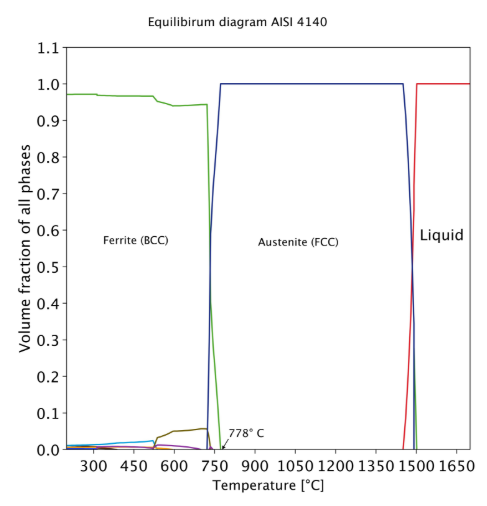
Figura 1. Diagrama tiempo-temperatura de austenización para acero Ck 45 (SAE/AISI 1045). | Image Credit: Figure 7, ASM International 2013
La formación de austenita implica cambios estructurales y composicionales influenciados tanto por la microestructura inicial como por la composición química del acero. Cuando los parámetros de austenización no se establecen adecuadamente: temperatura insuficiente, tiempo de permanencia corto o problemas de desempeño del equipo, como la falta de uniformidad térmica del horno, la transformación no se completa. El resultado es una microestructura que conserva fases no deseadas, lo que afecta la dureza, la estabilidad dimensional y la resistencia mecánica. Por lo tanto, cualquier microestructura que no logre transformarse completamente a austenita debido a los factores mencionados puede considerarse un caso de austenización insuficiente.
Causas de la Austenización Insuficiente:
Temperatura de austenización inadecuada: si la temperatura es demasiado baja, no se logra la disolución completa de ferrita o carburos.
Tiempo de empape insuficiente: un tiempo de empape (permanencia) demasiado corto impide la difusión homogénea del carbono en la austenita.
Distribución térmica no uniforme en el horno: produce zonas con distintos grados de transformación.
Composición química del acero: los elementos de aleación modifican la cinética de difusión y desplazan las temperaturas críticas de transformación.
Geometría y dimensiones de la pieza: las secciones más grandes demandan mayor tiempo de empape, para alcanzar el calentamiento completo.
Velocidades de calentamiento rápidas: pueden impedir la homogeneización de la microestructura y generar una transformación incompleta, especialmente en procesos por inducción.
Efectos de una austenización insuficiente
Microestructura heterogénea
Tal como se ilustra en el ASM Handbook, Volume 4A: Steel Heat Treating Fundamentals and Processes, la cinética de formación de la austenita depende fuertemente de la velocidad de calentamiento. A bajas velocidades, la homogeneización por difusión ocurre a temperaturas relativamente menores; en contraste, los calentamientos rápidos generan heterogeneidad microestructural, un efecto especialmente crítico en procesos como el endurecimiento por inducción o el calentamiento directo por flama. En otras palabras, la austenización insuficiente se presenta con mayor frecuencia cuando se emplean altas velocidades de calentamiento.
En consecuencia, una microestructura con composición heterogénea provoca variaciones en las temperaturas de transformación martensítica (Ms y Mf) a lo largo de la pieza. Durante el temple, las regiones con menor contenido de carbono transforman primero, originando una martensita más suave, mientras que las zonas más ricas en carbono transforman a menores temperaturas, generando tensiones internas y una microestructura inconsistente.
Mayor riesgo de deformaciones y fallas prematuras en servicio
Anteriormente se mencionó que el proceso de austenización implica un cambio en la estructura cristalina del material. Si este cambio no es homogéneo a lo largo de la pieza, se presentarán diferentes fases, resultando en un arreglo cristalográfico variado y, por ende, un cambio volumétrico. Por otra parte, calentar una pieza muy rápidamente provoca que el calor no se distribuya ni penetre de manera uniforme, causando transformaciones heterogéneas y, por lo tanto, tensiones debido a los cambios volumétricos en la estructura cristalina.
Reducción en la dureza y resistencia mecánica
Una austenización incompleta deja restos de ferrita o carburos no disueltos en la microestructura, que impide la transformación completa a martensita durante el temple, reduciendo la dureza final. Además, una menor cantidad de carbono en solución afecta negativamente la resistencia mecánica.
Aumento de la fragilidad y menor tenacidad
Una microestructura heterogénea (ferrita y perlita con martensita parcial y austenita retenida) disminuye la resistencia mecánica. Esto se traduce en menor capacidad para soportar cargas sin fracturarse.
Como prevenir la austenización ineficiente
Control preciso de temperatura y tiempo del horno
Figura 2. Ejemplo de un análisis de carga | Image Credit: Consultoría Carnegie
Para garantizar un control adecuado durante el mantenimiento, es fundamental utilizar termopares calibrados y ubicarlos estratégicamente dentro del horno para asegurar mediciones precisas. La calibración periódica previene errores en la lectura de temperatura, lo que contribuye directamente a la calidad del proceso. Además, es indispensable contar con la asesoría de un experto para determinar la vida útil recomendada de los termopares. Mantener una trazabilidad adecuada y realizar los reemplazos en tiempo y forma asegurará un funcionamiento óptimo del sistema.
Por otra parte, el uso de ventiladores internos en hornos de convecciones nos ayudara a mantener una uniformidad térmica dentro del horno, evitando zonas frías o calientes.
Otra forma de poder controlar la temperatura del proceso es el uso de registradores de temperatura o graficadores de temperatura. Estos dispositivos, conectados a termopares de contacto instalados directamente en las piezas, son especialmente recomendables para componentes con geometrías complejas con grandes espesores. Su función es registrar la temperatura en tiempo real y verificar que no existan fluctuaciones durante el tiempo de mantenimiento.
Distribución adecuada de la carga
En cargas donde es necesario realizar el tratamiento térmico de una cantidad considerable de piezas, es recomendable llevar a cabo un estudio para determinar la altura máxima de apilamiento que permita un flujo de calor adecuado y un calentamiento homogéneo. Un análisis preliminar puede realizarse colocando termopares estratégicamente en diferentes ubicaciones y en distintas piezas: por ejemplo, en la primera pieza de la carga, otra en la parte media y una más en la parte inferior de la torre de apilamiento.
Una vez que las piezas ingresan al proceso, es posible monitorear el comportamiento térmico de cada una de ellas, verificando que el tiempo de empape sea suficiente para que todas alcancen la transformación requerida al llegar a la temperatura objetivo, o bien, determinar si es necesario realizar ajustes en la configuración de la carga.
Uso simulación termodinámica para optimizar los parámetros del proceso
Cada grado de acero tiene una temperatura óptima de austenización determinada por su composición química. En los aceros al carbono (serie 10xx), estas temperaturas pueden estimarse mediante el diagrama Fe–C; sin embargo, cuando se incorporan elementos de aleación, dicho diagrama deja de ser suficiente. En esos casos, es necesario recurrir al cálculo de temperaturas críticas o al uso de herramientas más precisas, como simulaciones termodinámicas mediante software especializado, por ejemplo, Thermo-Calc®.
Aunque lo ideal sería tratar cada material a su temperatura específica, en la producción industrial esto no es eficiente, ya que implicaría procesar cada pieza de manera individual, lo cual ralentizaría la línea de fabricación y aumentaría el consumo de recursos, como tiempo y gas.
El uso de herramientas termodinámicas como ThermoCalc software ® permite evaluar cómo las variaciones en la composición química (debidas a tolerancias de colada o ajustes en elementos de aleación) afectan las temperaturas de transformación. Esto facilita la selección de una temperatura óptima de proceso que garantice que, para cada composición posible dentro de las especificaciones, las temperaturas de austenización sean las adecuadas. Con ello se optimiza el rendimiento del tratamiento térmico y se mejora la reproducibilidad del proceso.
Por ejemplo, en la figura 3, si un acero 4140 se calienta únicamente a 750°C (1380°F) en lugar de 850°C (1560°F), la ferrita no se disolverá por completo. Como resultado, después del temple se obtendrá una microestructura compuesta por martensita blanda y ferrita residual, en lugar de una martensita homogénea y dura. Esto reduce significativamente la dureza y la resistencia mecánica del material.
Figura 3. Diagrama de un eje para un acero 4140, (Fe, 0.4C, 0.8Mn, 0.2Si, 0.8Cr, 0.2Mo, 0.02Ni) | Image Credit: Consultoría Carnegie Figura 4. Histograma de la temperatura de transformación Ac3 para un acero AISI 4140 dentro del rango de especificación. | Image Credit: Consultoría Carnegie
En el histograma (figura 4) podemos observar que, incluso tratándose del mismo grado de acero, la temperatura A₃ puede variar aproximadamente 760−776°C (1400−1429°F) únicamente debido a las tolerancias químicas establecidas en la especificación. Si además consideramos la presencia de elementos residuales o microaleantes, es evidente que no podemos esperar el mismo comportamiento durante el tratamiento térmico ni las mismas propiedades mecánicas en todas las coladas.
En estos casos, herramientas termodinámicas como ThermoCalc software® permiten evaluar un conjunto amplio de posibles composiciones químicas y determinar una temperatura de austenización óptima que sea adecuada para todas las variaciones permitidas dentro de la especificación.
Diseño de curvas/rampas de calentamiento
Para asegurar que las temperaturas de transformación se alcancen de manera homogénea (tanto en procesos con cargas de alto volumen, como en piezas con geometrías variables) es recomendable implementar un calentamiento controlado. Aunque esto puede aumentar el tiempo de procesamiento, los beneficios incluyen una menor probabilidad de distorsión y la garantía de lograr una transformación austenítica completa.
La clave radica en diseñar un perfil adecuado de tiempo–temperatura, el cual dependerá de factores como las dimensiones de la pieza y las propiedades del material, entre ellas: difusividad térmica, capacidad calorífica, densidad y conductividad térmica.
Conclusión
La austenización insuficiente, conocida como underhardening, representa mucho más que una simple pérdida de dureza. Es una deficiencia metalúrgica que afecta la homogeneidad microestructural, la estabilidad dimensional y el desempeño mecánico.
Mediante un control riguroso de la temperatura, el tiempo y la uniformidad del horno, combinado con herramientas modernas de simulación, los ingenieros pueden asegurar transformaciones confiables, minimizar la distorsión y lograr resultados constantes y de alta calidad en el tratamiento térmico de los aceros.
Callister, W. D. 2019. Materials Science and Engineering: An Introduction. Hoboken, NJ: Wiley.
Herring, Dan. Metallurgical Fundamentals of Heat Treatment. Industrial Heating.
Krauss, G. 1980. Principles of Heat Treatment of Steel. ASM International.
Nuñez González, G. 1990. Fallas en los Tratamientos Térmicos para Aceros Herramienta.
Thomas, L. 2018. “Austenitizing Part 2: Effects on Properties.” Knife Steel Nerds. https://knifesteelnerds.com/2018/03/01/austenitizing-part-2-effects-on-properties/.
Totten, G. E. 2007. Steel Heat Treatment: Metallurgy and Technologies. Boca Raton, FL: CRC Press.
Acerca de la autora:
Ana Laura Hernández Sustaita Fundadora Consultoría Carnegie
Ana Laura Hernández Sustaita cuenta con Maestría en Ciencia e Ingeniería de los Materiales, Es fundadora de Consultoría Carnegie, una firma de consultoría y capacitación técnica especializada en el tratamiento térmico de aceros en México. Asimismo, se desempeña como Ingeniera de Soporte Técnico en Thermo-Calc Software, brindando asistencia a clientes en México, Canada y Estados Unidos de América. Ana promueve activamente la educación metalúrgica en Latinoamérica y fomenta la integración de herramientas computacionales en la práctica industrial del tratamiento térmico.
Insufficient austenitizing affects far more than final hardness. It disrupts phase transformation, weakens mechanical performance, and increases the risk of distortion or failure in demanding service conditions. In this Technical Tuesday installment, Ana Laura Hernández Sustaita, founder of Consultoría Carnegie, explains the metallurgical origins of incomplete austenite formation, how furnace uniformity, heating rate, steel chemistry, and part geometry contribute to the problem, and modern process-control and simulation strategies that ensure full transformation and repeatable, high-quality results.
This informative piece was first released inHeat Treat Today’sJanuary 2026 Annual Technologies To Watch print edition.
When a steel part is insufficiently austenitized, it is commonly referred to as underhardening, the resulting loss of hardness after quenching. However, in this article, we will extend the discussion beyond hardness alone, exploring the phenomenon of insufficient austenitizing, analyzing its causes and direct influence on microstructure and mechanical properties, and discussing modern strategies to prevent it.
The Role of Austenitizing in Heat Treatment
The main purpose of heat treatment is to produce a homogeneous or a desired mixed microstructure that ensures the required mechanical properties for the intended service conditions: tensile strength, impact resistance, yield strength, etc. Austenitizing is the first critical step for many processes. It involves heating the steel above the A3 temperature (typically 30–50°C or 85–120°F higher) to transform its microstructure into a face-centered cubic (FCC) lattice for a certain period of time. This step resets the steel’s structural history, particularly after casting, forging, or rolling, and defines the baseline for subsequent quenching and tempering operations.
What Is Insufficient Austenitizing?
Figure 1. Time-temperature-austenitization diagram for Ck 45 (SAE/AISI 1045) steel. | Image Credit: Figure 7, ASM International 2013
Austenite formation involves structural and compositional changes influenced by the initial microstructure and the steel’s chemical composition. When austenitizing parameters are not properly established, such as insufficient temperature, inadequate soaking time, or poor furnace performance (e.g., lack of thermal uniformity), the transformation remains incomplete. The result is a microstructure containing undesired residual phases that compromise hardness, dimensional stability, and mechanical strength. Therefore, any microstructure that fails to fully transform to austenite due to these factors can be directly associated with insufficient austenitizing.
Common causes of insufficient austentizing include:
Inadequate austenitizing temperature: Ferrite and carbides do not fully dissolve if the temperature is too low.
Insufficient holding time: A short soak time prevents uniform carbon diffusion throughout the austenite.
Thermal non-uniformity in the furnace (cold zones): This leads to regions with different degrees of transformations.
Chemical composition of the steel: Alloying elements modify diffusion kinetics and impact the critical transformation temperatures.
Geometry and dimensions of the part: Larger cross-sections require longer soak times for full heat diffusivity.
Rapid heating rates: Excessive heating, especially during induction hardening, can result in structural inhomogeneity and incomplete transformation.
Effects of Insufficient Austentizing
Heterogeneous Microstructure
As illustrated in the ASM Handbook, Volume 4A: Steel Heat Treating Fundamentals and Processes (2013), the kinetics of austenite formation depend strongly on the heating rate. At lower heating rates, diffusion-driven homogenization occurs at relatively lower temperatures, whereas rapid heating produces microstructural heterogeneity, an effect that is especially critical in induction or direct-flame heating. In other words, insufficient austenitizing is more likely to occur when high heating rates are used.
Consequently, a microstructure with heterogeneous composition leads to variations in the martensite transformation temperatures (Ms and Mf) throughout the part. During quenching, regions with lower carbon content transform earlier, producing softer martensite, while areas with higher carbon content transform at lower temperatures, resulting in internal stresses and an overall inconsistent microstructure.
Risk of Distortion and Premature Failure
The transformation from BCC or BCT to FCC (Defined: BCC: body-centered cubic; BCT: body-centered tetragonal; FCC: face-centered cubic) lattice during austenitizing involves a specific volume change. If this transformation occurs unevenly, differential expansion generates internal stresses, distortion, and in severe cases, microcracks. Rapid heating or poor furnace convection exacerbates these effects by producing steep temperature gradients across the part.
Reduced Hardness and Mechanical Strength
Incomplete transformation leaves undissolved carbides and residual ferrite, reducing hardenability and the amount of carbon in solid solution. This limits the formation of martensite during quenching and lowers final hardness and strength.
Increased Brittleness and Lower Toughness
A mixed structure of ferrite, pearlite, partial martensite, and retained austenite results in mechanical anisotropy and reduced energy absorption under impact loading. This condition increases the risk of brittle fracture, particularly in high-stress or cyclic applications.
How to Prevent Insufficient Austenitizing
Accurate Furnace Control
Figure 2. Example of loading analysis | Image Credit: Consultoría Carnegie
To ensure proper process control during the soaking stage, it is essential to use calibrated thermocouples strategically positioned inside the furnace to obtain accurate temperature measurements. Regular calibration prevents temperature reading errors and directly contributes to heat treatment quality. It is also important to get advice from an expert to determine the recommended service life of the thermocouples. Maintaining proper traceability and replacing them at the appropriate intervals ensures optimal system performance.
Additionally, the use of internal circulation fans in convection furnaces helps maintain thermal uniformity, preventing the formation of hot or cold zones.
Another method to monitor and control process temperature is using temperature data loggers. These devices, which are connected to contact thermocouples and placed directly on the parts, are especially recommended for components with complex geometries or large cross-sections. They record real-time temperature data throughout the process, allowing verification that no transient fluctuations occur during the soaking period.
Accurate Loading Distribution
For loads where heat treatment must be applied to a significant number of parts, it is recommended that a study be conducted to determine the maximum stacking height that will ensure proper heat flow and uniform heating. A preliminary assessment can be performed by strategically placing thermocouples in different locations and on different parts, for example, on the first part in the load, one in the middle section, and another at the bottom of the stacking tower.
Once the parts enter the process, their heating behavior can be monitored to verify that the soaking time is sufficient for all pieces in the stack to complete their transformation upon reaching the target temperature or to determine whether adjustments to the loading configuration are necessary.
Use of Thermodynamic Simulation to Optimize Process Parameters
Each steel grade has an optimum austenitizing temperature in function of its chemical composition. For carbon steels (10XX series), these temperatures can be estimated using the Fe–C diagram; however, once alloying elements are added, this diagram is no longer sufficient. In such cases, it becomes necessary to rely on critical temperature calculations or on more advanced tools such as thermodynamic simulations using specialized software, like Thermo-Calc®.
Although the ideal scenario would be to heat treat each material at its specific optimum temperature, this approach is impractical in industrial production; the required processing of each part individually would slow the manufacturing line and increasing resource consumption, including time and fuel.
Thermodynamic tools such as Thermo-Calc allow engineers to evaluate how variations in chemical composition (arising from casting tolerances or adjustments in alloying elements) affect transformation temperatures. This enables the selection of an optimum processing temperature that ensures complete austenitization for all possible compositional variations within the specification. As a result, the heat treatment operation becomes more robust, more reproducible, and more energy efficient.
For example, in Figure 3, if a 4140 steel is heated only to 750°C (1380°F) instead of 850°C (1560°F), the ferrite will not fully dissolve. As a result, the microstructure will consist of soft martensite and residual ferrite after quenching, rather than a fully homogeneous and hard martensitic structure. This significantly reduces the material’s hardness and mechanical strength.
Figure 3. Equilibrium diagram, AISI 4140 0.38C, 0.78Mn, 0.85Cr, 0.22Mo (%wt.) | Image Credit: Consultoría CarnegieFigure 4. Histogram of Ac3 transformation temperature for AISI 4140 steel within the specification range. | Image Credit: Consultoría Carnegie
We can observe in the histogram (Figure 4) that even within the same steel grade, the A3 temperature can vary from approximately 760−776°C (1400−1429°F) solely due to the composition tolerances specified for the alloy. If we also consider the presence of residual or microalloying elements, it becomes clear that we cannot expect identical behavior during heat treatment or identical mechanical properties across all heats.
In such cases, thermodynamic tools allow us to evaluate a batch of possible chemistries and determine an optimal austenitizing temperature that is suitable for all compositional variations.
Heating Curve Design
To ensure that transformation temperatures are reached uniformly (whether in processes involving large loads or parts with variable geometries), it is advisable to implement controlled heating rates. Although this approach may increase processing time, the benefits include reduced distortion risk and assurance of complete austenitic transformation.
The key is to design an appropriate time–temperature profile, which depends on factors such as part dimensions and material properties, including thermal diffusivity, heat capacity, density, and thermal conductivity.
Conclusion
Insufficient austenitizing, also known as underhardening, represents far more than a loss of hardness. It is a metallurgical deficiency that affects microstructural homogeneity, dimensional stability, and mechanical performance. Through rigorous control of temperature, time, and furnace uniformity combined with modern simulation tools, engineers can ensure reliable transformations, minimize distortion, and achieve consistent high-quality results in steel heat treatment.
Callister, W. D. 2019. Materials Science and Engineering: An Introduction. Hoboken, NJ: Wiley.
Herring, Dan. Metallurgical Fundamentals of Heat Treatment. Industrial Heating.
Krauss, G. 1980. Principles of Heat Treatment of Steel. ASM International.
Nuñez González, G. 1990. Fallas en los Tratamientos Térmicos para Aceros Herramienta.
Thomas, L. 2018. “Austenitizing Part 2: Effects on Properties.” Knife Steel Nerds. https://knifesteelnerds.com/2018/03/01/austenitizing-part-2-effects-on-properties/.
Totten, G. E. 2007. Steel Heat Treatment: Metallurgy and Technologies. Boca Raton, FL: CRC Press.
About The Author:
Ana Laura Hernández Sustaita Founder Consultoría Carnegie
Ana Laura Hernández Sustaita holds a Master’s degree in Materials Science and engineering. She is the founder of Consultoría Carnegie, a technical consulting and training firm specializing in steel heat treatment in Mexico. Additionally, she works as a technical support engineer at Thermo-Calc Software, providing assistance to clients across México, Canada, and United States of America. Ana actively promotes metallurgical education throughout Latin America and advocates for the integration of computational tools into industrial heat treatment practice.
In this episode of Heat TreatRadio, host Doug Glenn invites Dennis Beauchesne of ECM USA to explore the technology, benefits, scalability, and sustainability of modular heat treating systems. Together, they discuss how shared utilities, automated transfers, and adaptable heating cells can replace multiple standalone furnaces without compromising quality or precision. Learn how these systems streamline and simplify operations for future expansion — one cell at a time.
Below, you can watch the video, listen to the podcast by clicking on the audio play button, or read an edited transcript.
The following transcript has been edited for your reading enjoyment.
Introduction
Doug Glenn: I am very privileged to have with me today, Dennis Beauchesne from ECM USA. We’re going to be talking about modular heat treating systems, which is a growing category of equipment.
ECM Synergy Center (00:50)
Doug Glenn: Tell me about ECM’s Synergy Center, which is where you are at right now, on the shop floor.
The ECM Flex 600TG vacuum furnace located in the ECM Synergy Center Source: ECM USA
Dennis Beauchesne: I’m standing here in the middle of our Synergy Center. It’s about a 5,000-square-foot facility that is dedicated to proving out client parts for testing various processes, mostly LPC, but we also do a number of other processes here. We have a full metallurgical lab, 3D microscope, a number of tools, including a CMM that we can do before and after heat treat distortion testing for clients that want to know how much their parts move.
It’s a dedicated center just for clients to use. We also use the center for pre-completion of installations, final testing, and training, such as training on maintenance, understanding the software, and how everything works together.
Doug Glenn: It’s proof of process plus much more — helping clients’ proof of process.
Dennis Beauchesne: Absolutely. That’s a big part of convincing people that this process is for them and that it works on their part. We can send them ten different reports of an exact same material and part, but they want to know what their part will do.
What is Modular Heat Treating? (02:50)
Doug Glenn: On a very basic, rudimentary level, what is modular heat treating and how does it differ from what might be considered standard or normal heat treating?
Dennis Beauchesne: A modular heat treat system is one that works together to have more than one furnace working in the same platform. You may have a shop that has five or six vacuum furnaces separated — they each have their own door, vacuum system, electrical supply, quench motors…those types of components. Or you may have a series of batch IQ furnaces for carburizing; those systems are one off, which means they are individual, independent systems.
In a modular system, you try to utilize those facilities for the use of multiple heating chambers. Instead of having one vacuum furnace with one set of pumps and one gas quench motor, what we would do is have three to eight heating cells that would be utilizing one quench, depending on the process timing; that’s all done with an internal transfer car and we try to utilize one vacuum system. It’s much smaller than what you would have for three, four, or even eight cells.
If you had oil or high pressure gas quenching, which is what’s dominating right now in the modular heat treat business, you could supply basically six batch IQ hot zones to one oil quench.
The savings then are huge simply by removing five or six other quench tanks in front of this system, as well as leveraging the floor space (and the number of pits you have to dig). Other advantages including utility savings and utilizing equipment across a number of heating chambers.
Doug Glenn: This modular approach is basically separate chambers that are dedicated to doing whatever that chamber is doing, and they are all in some way interconnected. For standard units, you would heat up, pre-process, do the actual process itself, cool down, all in the same chamber. In a modular unit, you move from chamber to chamber to do each of those separate steps.
Dennis Beauchesne: Yes, I refer to it as a continuous batch.
Doug Glenn: Continuous batch. We were talking before we actually hit the record button with your colleague there, Allison DeAngelo, who just got done visiting the Heat Treat Boot Camp. We were talking about different types of furnaces, and we started talking about continuous vacuum, which of course, is almost a misnomer — a vacuum can’t be continuous because you have to open it up and break the vacuum to get stuff out. Anyhow, we talked about it basically being a batch, right? A batch furnace that’s continuous, a continuous batch furnace.
Benefits of Modular Heat Treating (06:35)
Now that we have a basic understanding of what these modular systems are, why would companies want to move from the standard type of heat treating system to a modular system?
Dennis Beauchesne: Manpower. If you are running five or six vacuum furnaces, you are going to need a number of people to open the doors, put new loads in, those kinds of tasks. With a modular system, you only have one entry or one exit area. Therefore, you are only going to load once every 15-20 minutes, and the system is going to take over and control that load going through the system.
In addition, especially in a carburizing atmosphere situation, you can have every load be a different case depth — a different process in each cell — and then the next load that goes in that same cell can be totally different from the one before. For instance, if you had a batch IQ, you typically use the same carbon potential, and you are typically going to run the next load almost identical to the one before. In contrast, with the modular system, each cell can run a different process every load.
It’s also easier to integrate automation if you are doing capacity increases.
Throughput Comparison (08:00)
Doug Glenn: What is the comparison of throughput between a standard unit and a modular unit?
Dennis Beauchesne: The throughput comparison is interesting because you typically can use a little higher temperature for a carburizing and a little higher carbon potential, and of course that’s what we specialize in here with the modular systems. You can achieve about a 30-40% gain in your cycle time. That furnace is operating very close to 100% occupancy, because when that load is done, you are moving it out right into the gas quench. Then, the next load comes and goes right into it.
Doug Glenn: You are able to increase your throughput because you have basically 100% utilization of the equipment or very close to that. Comparatively, you don’t necessarily have that in the standard equipment.
Product Quality Comparison (09:15)
Doug Glenn: Do modular systems produce higher quality products?
Dennis Beauchesne: The quality of the parts coming out of the system is improved. A vacuum environment is a very clean environment, especially if we are considering atmosphere and low pressure carburizing — it’s in a vacuum. We typically do everything in high pressure gas quenching. However, even in oil quenching under vacuum, you are going to have a much cleaner part.
Also in low pressure carburizing, the carburizing is much more uniform throughout the part because we heat it to temperature under nitrogen before the part gets to austenitizing temperature to start attracting carbon. We make sure that the full part, that’s the tooth, the root, every piece of the part, is at temperature before we start adding carbon to the load, which makes a more uniform case depth, and therefore makes a stronger part.
Doug Glenn: Since each module, each chamber, is dedicated to doing what it is supposed to do, it seems like the consistency and the reliability of the parts being processed in a modular system have a much better chance of being higher quality.
Dennis Beauchesne: You do not have six different variable chambers or six different variable systems. You just have to look at monitoring the connection between those and understanding that the vacuum levels are all the same across the levels and across the cells. Each cell can meet a different temperature and run a different process, but those are consistent across the board.
Typical Dedicated Cells/Chambers (11:10)
Doug Glenn: What would be the typical dedicated cells/chambers of a modular system?
Dennis Beauchesne: It is dependent on the processes. They are most widely used for vacuum carburizing. For pre-oxidation and preheating, we usually use an air oven outside of the system, and we connect that with an external loader. Before the load goes into the modular system, the load will go through a regular air oven, be heated to around 700°F (400°C), and then the load will be moved in.
For sintering and those kinds of applications, there is a debind step or a preheat step that would be done in one cell. Some of the processes that can be done in a modular system include:
Low pressure carburizing
Low pressure carbon nitriding (LPC)
FNC (ferritic nitrocarburizing)
Nitriding
Debinding
Sintering
Neutral hardening
The most prominent process right now is LPC, and that is being used all over the world in these systems.
Advantages of a Modular Unit for Captive Heat Treaters (12:53)
Doug Glenn: Why would a modular unit be beneficial for a captive heat treater, someone who does their own in-house heat treating, which probably means they’ve got potentially high volume, low variability as far as their workloads?
Dennis Beauchesne: The modular unit has many different advantages. First of all, floor space. You are going to save a lot of floor space by not having multiple furnaces set up separately. You will also save utilities because you would not have as many vacuum pumps or electrical systems running these furnaces on their own. You will have some shared service and utilities in that fashion.
Doug Glenn: That would also likely lead to maintenance cost savings as well, correct?
Dennis Beauchesne: Yes, it all goes down the line. Anything that you have multiples of, you are going to have much less costs than on a joint system. The modular system might be a little larger than one singular unit, but there will be fewer of them.
For vacuum carburizing applications in a captive shop, the quality and cleanliness of the part is very, very important. Gas quenching lends itself to no oil in your plant, no washers necessary for a post-quench. Typically, there’s a washer before the process starts, but you do not have to have any wash to get the oil off of the parts with a modular unit — you do not have to reclaim the oil or the water from the washer. You would not have waste oil in your plant either or any oil on your plant floor. These are some of the reasons some of the larger captive shops have gone to the modular systems.
Also, safety: There are no open flames with a modular unit, no risks of fire on the systems. They are also easier to maintain. For a fully operational, let’s say, eight-cell system for high production, captive operation, it would only take about five hours to cool that whole system down if you had to go in and work on the whole system. In comparison, it’s going to take you three to four days sometimes to cool down a typical atmosphere, high-temperature furnace.
It also takes time to heat the system up again. In a modular system, it takes about an hour and a half to heat the system up again and then you are ready to start running. That means now you can schedule your downtime on weekends or holidays. You do not have to have staff present to run anything.
You also do not have to have a secondary equipment, like Endo generators running to feed the carburizing gas. The carburizing gas is using acetylene out of cylinders, it’s not a regenerative system. You do not need a separate piece of equipment to feed to the furnace.
Another benefit is CapEx expansion. Typically, captive heat treaters do not want to buy everything upfront because their volumes are going to increase over time. In the beginning, they typically only need one or two cells ready to do a small amount of production so they can prove out the production and prove out the system. Then they can start building the system with more cells and more capacity later on. Generally, it’s two to three days of downtime to add a cell to a system. It’s very convenient to do that with a modular system. All of the utilities are typically alongside the modular system so that you can easily add those or add a cell to it over a short period of time, and those cells can be ordered a year or two down the road whenever you might need that.
You also can order peripheral equipment, like extra temper ovens or additional automation. You can add a robotics system to the layout as well. That’s why captive shops are very interested.
Finally, workforce: It’s a little bit easier to get someone to work on a modular system. These systems are completely clean and white. The one located in our Synergy Center has been there for eight years. We use it every single day, and it’s a very clean aesthetic environment for someone to work in. These systems are also water cooled, which means not a lot of extra heat in the building around you to work in.
Advantages of a Modular Unit for Commercial Heat Treaters (17:59)
Doug Glenn: What are some advantages of modular units for commercial heat treating?
Dennis Beauchesne: On the commercial heat treat side, modular units are typically useful because you can get multiple processes out of similar cells and you can have a system that has oil and a gas quench.
You can have a lot of flexibility in that one system that you have in the plant. I’ve visited hundreds of captive and commercial heat treaters. They generally have a number of furnaces in one area of the plant, and a number of furnaces in another area of the plant. A modular system gives you all the capability in one machine and one tool: oil quenching, gas quenching, FNC, nitriding low pressure, carburizing, carbonitriding, and neutral hardening all in one piece of equipment.
Automation and Robotics with Modular Heat Treating (18:57)
Doug Glenn: What automation and robotics advantages are there with modular systems?
Dennis Beauchesne: This is the new trend. People that have modular systems are now considering, “How do I automate the system to get more production out of it?” And what we’ve been doing the last five years especially is implementing systems that use CFC fixtures.
CFC fixtures are very robust in the furnace but sensitive to being controlled outside. Therefore, what we try to do is have the CFC fixtures be utilized in an automation that no humans have to interact with it. We usually use robots for external loaders and internal loaders to move the fixtures through the process.
This causes you to have a lighter load, which means less heating time, less energy being consumed. Also, the fixtures last three to four times longer if they’re not damaged. But of course, all of these systems can be using regular alloy steel as well, and we can fixture different parts. You can use baskets, we are now doing bulk loading where we have parts that are filled into baskets and then processed. We are doing that with vacuum carbonizing as well, not just neutral hardening.
So it’s really interesting to see how the limits are being pushed, as well as the different materials that we are gas quenching now. I know 20-25 years ago, we were quenching some simple materials that were very high hardenability, and today we’re quenching a lot of less hardenability steels.
Doug Glenn: Is that primarily due to increase of pressure in the quench?
Dennis Beauchesne: It’s pressure, it’s flow, it’s the intensity of the gas going through the parts. It’s also heat removal as well — heat exchangers, removing the heat out of the load faster. We also have reversing gas quench motors to reverse the flow inside from top to bottom, bottom to top, in the middle of the cycle.
Sustainability of Modular Heat Treating (22:24)
Doug Glenn: Do these systems promote sustainability and greenness?
Dennis Beauchesne: Absolutely, especially when it comes to carburizing. These systems have been compared against typical atmosphere carburizing cycles, and only about 4% of the carburizing time has gas injection, when we are actually injecting acetylene and having hydrocarbons being used in the process.
If you took the same cycle times, seven or eight hours of a carburizing cycle, you are flowing Endo gas or nitrogen methanol in the system for that full time. In contrast in a vacuum carburizing system, it’s 4-5% of the time of the cycle that you’re injecting into the furnace. Ultimately, you only have about 10% of the CO2 output that you would have in a typical atmosphere furnace.
As mentioned previously, there’s also no oil in your plant. You’re not reclaiming oil out of the water and the wash or off the floor or in your car when you leave your heat treat shop.
How Does the Modular Heat Treating System Work? (23:40)
Doug Glenn: Let’s talk through the process a little bit. You provided us with figures to aid in describing the process. We have included these. Describe how the system works.
Dennis Beauchesne: This animation is a plan view of one of our Flex systems. In the center, going left to right, is a tunnel section. This tunnel section is about an 8-foot diameter. It has an automated loader that moves down left to right or horizontally, and it transfers loads from each cell to another, in and out.
On the bottom left is a loading/unloading chamber. In that loading/unloading chamber, we remove the air once the load is put in there, and then we balance the vacuum on that cell to the tunnel’s vacuum. Then we’re capable of moving that load to an available heating cell, and that would be on the right of the system — on the top right or the bottom right of the tunnel, those are heating cells. Then recipe for that particular load will be loaded into that cell. While that load is processing, another load will be moving into the tunnel and into the other heating cell as well.
On the top left is the gas quench cell, which could be in this orientation or instead have an exit on the back as well. In this system, you could do neutral hardening, carbon nitriding, LPC, a number of the processes. This is a very valuable tool, especially in a commercial heat treat heat treat shop.
Doug Glenn: Is this whole unit, including all four chambers under vacuum? I noted there are separation doors on the purge and the entry chamber. Can this area be vacuum sealed?
Dennis Beauchesne: Yes. There are vacuum seals on the loading/unloading chamber on the bottom left and then the top left. The gas quench also has a seal from a pressure standpoint. The two heating chambers have a graphite door — we call it the flap door, and it just flaps and it doesn’t really seal actually against another face of graphite. It’s graphite-to-graphite. We pull vacuum out of there through the tunnel to create the central vacuum pressure in the system. We also pull vacuum from the cell itself, and we could also have a separate door on the front of the unit if the process necessitates that or if we feel that a door is needed there by a client.
In a normal state or a standard unit, there are no hot seals on the door, only vacuum seals on the loading/unloading chamber and the gas quench.
Doug Glenn: In the animation, your vacuum pumps are down in the bottom right, correct?
Dennis Beauchesne: Exactly, that’s a process pump.
Doug Glenn: What is located in the top left?
Dennis Beauchesne: On the top left, we have a gas quench tank. We want to ensure we have enough gas pressure and volume there to quench the load quickly. It’s very important to get the gas through the gas quench quickly.
ECM Flex 600TG vacuum furnace with two added heating cells / Source: ECM USA
Now, we have added two more additional heating cells and a central tunnel section. In essence, you just doubled the space, doubled the capacity of the unit, where you only added 50% of the space of what you had for capacity before.
We are still utilizing the same gas quench and the same loading/unloading cell. We only added utilities for the two heating cells, not for a whole gas quench or oil quench capability there; this can be added in a very short time.
Doug Glenn: Now I’m gonna go let this video roll here for a minute. There we go.
ECM Flex 600TG vacuum furnace with four added heating cells for six heating cells total
Dennis Beauchesne: So now we added another 50% capacity with two more heating cells (six heating cells total) and a tunnel section. Typically, what you want to do is to have the tunnel sized for about five years out for your capacity and then buy the cells as you need them and have it grow so then the tunnel is ready to implement.
We have just tripled the capacity of this installation, and we are only still using the same gas quench and the same loading/unloading cell. Generally, this system could go to eight cells and have just one gas quench, that’s our typical orientation.
Doug Glenn: It looks like we also added a discharge side here. Whereas before we were going in and out.
Dennis Beauchesne: Yes, this adds to the efficiency of the system because the load is already in the gas quench when it’s finishing, so it just exits out the back, out the door.
Doug Glenn: Now what do we have here?
ECM Flex 600TG vacuum furnace processing different treatments in each cell. See animation above to watch the animation in motion.
Dennis Beauchesne: We have the loads entering, and the loads will go to the first cell that is available (empty). Then that recipe would be downloaded for that cell, and then the next load will go to the next available heating cell and download that recipe into that cell. These could be two different loads.
One load could be for neutral hardening; one could be for carburizing. One could be for carburizing in a low case depth. The other one could be carburizing at a deeper case. In this case, we just see the gas quench on here, but this tunnel could also be outfitted with an oil quench as well, and you could have one load go into gas, quench one load, go into oil quench or both going to either.
Doug Glenn: This gives people a sense of what the process looks like.
Processes and Materials for the Modular System (30:29)
Doug Glenn: Are there any processes or materials that do not make sense to process them through one of these systems?
Dennis Beauchesne: If you are doing a lot of annealing and normalizing, those are longer cycles. There is some regulated cooling that occurs. This is not really the type of equipment investment that you would want to make for those processes. If you were going to use it for a few loads in your plant where you received parts that weren’t annealed or you wanted to try to anneal a part for a particular process before you went to full production, you could certainly use a modular system for that, but it’s not a cost effective methodology. Neither would we recommend preheating in the cell. However, it is very flexible for a number of other processes that we have mentioned.
The size of the part is also important to note. These systems are typically 24 inches wide and about 39 inches long and about 28 inches high. However, we will soon have a new system, the Flex Max, a 12-9-9 system. It’s a 36×48 unit that comes with an oil quench and is modular, like this. We can either do an oil quench or a slow cool cell on that system. So, we will have that capability of 36×48 in that modular system.
Other than that, restrictions on material? Very few there. Like I said, you would not want to do annealing and normalizing on a lot of parts, but you could do it in these units.
Doug Glenn: It sounds like the sweet spot is surface modification type applications, and some sintering is possible with dedicated chambers.
Dennis Beauchesne: Yes, sintering and brazing is also possible.
Doug Glenn: Does that include aluminum brazing?
Dennis Beauchesne: Not aluminum brazing, but some brazing applications.
Expenses with Modular Heat Treating Systems (33:03)
Doug Glenn: What would be considered capital expenses for this modular system?
Dennis Beauchesne: As far as capital expenses, it’s not a furnace-to-furnace comparison. Clients always ask how much our furnace is. But companies need to first take two steps back and take a look at their incoming material, how they would like to be able to modify that incoming material in their heat treat process to make sure that their outgoing quality is higher than it is today. That’s the kind of benefit that this type of modular system gives you — a better quality part, safety in your plant, and a better quality work environment with being able to turn the system off and not need additional personnel around.
These are all factors that have to be considered when thinking about the CapEx expenditure and investment. When we consider these factors, a modular system investment is a much better situation than looking at a furnace-to-furnace replacement, and that’s really the thought process that clients need to go through to understand the actual investment and value of the system.
Doug Glenn: What about the operational expenses?
Dennis Beauchesne: For instances, if you had a batch IQ sitting there, you would typically keep it running whether it has a load in it or not. With a modular system, you just shut off that cell that you’re not using. It does not take any more energy. If you are not working five days a week, you do not use it on the weekends — you shut it off. You do not use it during Christmas shutdown or any holiday shutdown, vacation shutdown. You’re able to shut it off and that means saving a lot of energy and labor by having it off.
Also, in the opposite way, you could run it lights out if you wanted, as well. You could stock up a number of loads on the automation before you leave, have the system operate it, run it, and have the load come back out before the morning. You could have it time start as well, if you wanted to start it on Monday at 5 AM, but you will not be there till 8 AM. You would come in and the furnace would be hot and ready to run a process.
There are a number of operational advances over the typical operational heat treat that’s out there today.
Doug Glenn: How does maintenance work with these systems? Say your heating element goes bad in cell number three, do I have to shut the whole system down to fix or can I fix number three and leave the rest of the system up and running?
Dennis Beauchesne: In this situation if you had a tunnel like we showed, you would typically shut off that cell; that is, if you knew that heating element was out or it wasn’t heating properly, you could shut off that cell, de-validate is what we call it, and then keep running the rest of the system until you had a window in your production that you could shut the whole system to get into that heating element.
If you had a system with doors on the front, it could be possible to go in the back while the system is operating. Then, it would be all based on your safety requirements for your plant and those kinds of things.
To do that, we have another system called the Jumbo, and it is much more flexible in the maintenance world. It has a vacuum car that moves down on rails and docks and mates with every heating cell on the system. In that line, the heating cell can actually be isolated from the rest of the line. You would just slide it back (It’s on wheels, it slides back about three feet away from the line), you put in a new piece of safety fence, and you continue to run your line. You can completely lock out/tag out that cell and work on it completely.
Doug Glenn: How would you approach a vacuum leak since the whole system is connected, right? I believe you mentioned these are graphite-on-graphite doors.
Dennis Beauchesne: You would want to fix the leak before you move on. Especially if it’s a bad leak. If it’s something that’s causing you to not maintain your process pressure, you certainly don’t want to do that, and that’s true with every vacuum piece of equipment.
ECM Modular Systems (38:55)
Doug Glenn: How many of these modular type systems does ECM have out in the marketplace?
Dennis Beauchesne: The Flex is the most popular modular system, which we discussed with the animation. We also have a number of Jumbos systems, and the unit in our Synergy Center is called a Nano, which has become more and more popular these days. The Nano has three different size chambers, but they’re typically smaller, 20x24x10 inch high size chamber. I explained a little bit about the Flex and the Jumbo is the same.
Out of those three systems, we have more than 350 modular systems, not just the heating cells, but more than 350 systems that are out in the marketplace today operating, running parts every day, running millions and millions of parts every week. Those systems are comprised of about 2,000 heating cells. As much as people hear about this being a new technology, it has actually been around about 30 years, and many companies have been using these systems and have replaced a number of pusher furnaces and those style furnaces for high-capacity installations especially.
Doug Glenn: Okay, that sounds good. I really appreciate your time.
About the Guest
Dennis Beauchesne General Manager ECM USA
Dennis Beauchesne joined ECM over 25 years ago and has since amassed extensive vacuum furnace technology experience with over 200 vacuum carburizing cells installed on high pressure gas quenching and oil quenching installations. Within the last 10 years, his expertise has expanded to include robotics and advanced automation with the heat treat industry high-demand for complete furnace system solutions. As General Manager of ECM USA, Dennis oversees customer supply, operations and metallurgical support for Canada, U.S., and Mexico for ECM Technologies. He has worked in the thermal transfer equipment supply industry for over 30 years.