The Heat Treat Doctor® has returned to offer expert advice to Heat Treat Today readers and to answer your questions about heat treating, brazing, sintering, and other types of thermal treatments as well as questions on metallurgy, equipment, and process-related issues.
This informative piece was first released in Heat Treat Today’sMay 2025 Sustainable Heat Treat Technologies print edition.
Stress relief is a heat treatment operation primarily intended to reduce or redistribute the internal stresses present in steel and other materials that were introduced from various manufacturing processes like bending (see Figure 1), drawing, rolling, shearing, forging, sawing, machining, grinding, milling, tuning, welding, etc., as well as from prior mill processing. The application end use of a part ultimately defines its allowable stress state. So, what is it, and how does one perform a stress relief operation? Let’s learn more.
Figure 1. Type of plastic deformation and residual stress during bending
How Does It Work?
Contact us with your Reader Feedback!
Processes that depend on slow cooling (e.g., annealing, normalizing, stress relief) do so for a variety of reasons: to soften a material for subsequent operations (e.g., machining), to improve chemical homogeneity, to refine grain size, to relieve stresses, and for such reasons as embrittlement relief or magnetic properties (see Haga, L. J.). Residual stresses can compromise a material’s mechanical properties, leading to issues such as warping, cracking, and premature failure under service loads. As a general rule, the larger or more complex the part and/or the more aggressive certain manufacturing processes, the greater the amount of internal stress present.
Stress relief can be differentiated from other slow cooling processes in that it is most o en performed below the lower critical temperature (Ac1). Time at temperature depends on such factors as the complexity of the part, and enough time must be allowed to achieve the desired reduction in residual stress level. Following stress relief, the steel is cooled at a sufficiently slow rate to avoid formation or reintroduction of excessive thermal stresses. The stress relief process should be designed to reduce or eliminate internal stresses in a material without significantly altering its microstructure.
Stress relief helps improve a material’s stability, especially in applications where parts are subjected to cyclic or dynamic loading, since residual stresses can lead to fatigue failure over time. Stress relief helps to reduce these stresses, thus improving the material’s fatigue resistance and overall stability. During processes like welding, casting, or machining, the rapid cooling of steel can result in uneven contraction, leading to distortion in the final part. Stress relief helps reduce distortion, ensuring the part maintains its intended dimensions and shape.
Stress relief is particularly important after welding, which can introduce a significant amount of residual stress again resulting in distortion and/or cracking in service if not negated. Stress relief helps to minimize these effects and ensures the structural integrity of welded components.
How Do We Perform a Stress Relief Operation?
For carbon and alloy steels, stress relief operations are typically performed at 105°F–165°F (40°C–75°C) below the lower critical temperature, that is in the range of 930°F–1200°F (500°C–650°C). It is also important to understand the elimination of stress is not instantaneous, being a function of both temperature and time for maximum benefit. Typically, soak times of one hour per inch (25 mm) of maximum cross-sectional area (once the part has reached temperature) are recommended, with most soak times being in the range of 30 minutes to 2 hours, depending on the size and thickness of the part. Larger parts or components with complex geometries may require longer holding times to ensure uniform stress relief throughout the entire part. Alloy steels, especially if used in highstress environments (e.g., turbines, pressure vessels) benefit significantly from stress relief to improve their durability and fatigue resistance.
After removal from the furnace or oven, the parts rely on slow cooling to achieve a minimal residual stress state — the desired effect. Parts are typically still air cooled. Rapid cooling will only serve to reintroduce stress and is the most common mistake made in stress relief operations. A properly performed stress relief cycle often removes more than 90% of the internal stresses.
For tool steels the process is similar; it is common to perform a stress relief operation in the temperature ranges of 925°F–1025°F (500°C–550°C) for most tool steels or 1115°F–1300°F (600°C–700°C) for hot work and high-speed grades, allowing the parts to slowly cool to room temperature before subsequent operations. For stainless steels, the situation is more complex (see Atmosphere Heat Treatment, Volume 1 and ASM International’s Metals Handbook). Stress relief is done in the range of 550°F–800°F (290°C–425°C), which is below the sensitization range to avoid precipitation of carbides and reduced corrosion resistance. The operation depends on the form of the material, the operation being performed (e.g., machining), or if a completed assembly is to have a stress relief performed on it (Figure 2).
Figure 2. A combination of factors contributed to excessive warpage of 300 series stainless steel plates (including the method of fixturing used, the stress relief temperature selected, and the manufacturing process used to cut the plates).
At stress relief temperature, atomic movement increases, allowing the material to “rearrange” its internal structure, thus effectively relieving internal stresses. Steel is usually held at the stress relief temperature to ensure the remaining stresses are evenly distributed and reduced.
How Slow Is Slow?
Once the desired stress relief temperature has been reached and the part held for the appropriate time, the steel is then cooled slowly, typically in air, to prevent reintroduction of new thermal stresses. Rapid cooling (such as quenching) is to be avoided. A “still air cool” is often recommended, being defined as cooling at a rate of 40°F (22°C) per minute or faster to 1100°F (593°C) and then at a rate of 15°F–25°F (8°C–14°C) per minute from 1100°F–300°F (593°C–150°C). Below 300°F (150°C), any cooling rate may be used.
Poor Man’s Stress Relief
In hardening, rapid cooling/quenching alone or in combination with pre-existing internal stresses can result in unwanted distortion and even brittle fracture near welds in certain grades of metal. Stress corrosion cracking is another concern. For these reasons, a number of heat treaters introduce a “stress relief hold” during hardening or case hardening treatments. This involves heating of a workload to an intermediate temperature, in the range of 1000°F–1300°F (538°C–705°C) and soaking for a period of time equivalent to one hour per inch of maximum cross-sectional area. The idea is to allow for stress relaxation so that more predictable dimensional change occurs on quenching.
Types of Stress Relief Operations
While the basic process parameters for stress relief are largely the same, various types of methods can be used to achieve the desired results. Depending on the size and type of components being treated, one can use:
Batch furnaces where the load sits in the furnace or oven while being heated and soaked. This often allows precise control of these process variables. The load is then removed from the furnace for cooling.
Continuous furnaces where large volumes of component parts are moved through a heated section (usually but not always with multiple control zones) and then conveyed into one or more cooling sections as parts move through the furnace. The cooling sections are typically 2–2½ times the length of the heated section for adequate cooling time.
Induction heating for localized stress relief or when dealing with large or irregularly shaped components where heating the entire component part may not be desired. Stresses can be relieved in precise locations without affecting the entire part.
Vibratory Stress Relief, which uses mechanical vibration to redistribute residual stresses without the need for high temperature treatments. This technique has been used on castings and in some cases large, welded structures. The amount of stress relieved is often significantly less than thermal methods.
Post-Weld Heat Treatment (PWHT), often used during or after fabrication of welded steel structures. (Note: PWHT will be the subject of next month’s Ask The Heat Treat Doctor® column.)
In Summary
Stress relief is an oft-ignored but important heat treat process. By reducing internal stresses during manufacturing, stress relief operations help minimize post-heat treat distortion and improve mechanical properties. Understanding the significance of stress relief, selecting the best time/temperature cycles for a given material, and carefully controlling the process (especially as it relates to cooling rate) are keys to achieving the final result.
References
Accendo Reliability. “Residual Stresses in Metals.” Effective April 3, 2024. https://accendoreliability.com/residual-stresses-inmetals/. ASM International. “Metals Handbook, 10th ed., vol. 4, Heat Treating, Cleaning and Finishing.” (1991).
Grenier, Mario and Roger Gingras. “Rapid Tempering and Stress Relief Via High-Speed Convection Heating.” Industrial Heating, May 2003.
Haga, L. J., “Understanding Slow Cooling: Part 1 — Stress Relief.” Heat Treating, (October 1980).
Hebel, Thomas E. “Sub-harmonic Stress Relief Improves Mold Quality.” Mold Making Technology, 2009.
Herring, Daniel H. Atmosphere Heat Treatment, vol. I. BNP Media, 2014.
Herring, Daniel H. “Stress Relief.” Wire Forming Technology International (Summer 2010).
Lindqvist, Stefan and Jonas Holmgren. “Alternative Methods for Heat Stress Relief.” Master’s Thesis, Lulea University of Technology, 2007.
About the Author
Dan Herring “The Heat Treat Doctor” The HERRING GROUP, Inc.
Dan Herring has been in the industry for over 50 years and has gained vast experience in fields that include materials science, engineering, metallurgy, new product research, and many other areas. He is the author of six books and over 700 technical articles.
The Heat Treat Doctor® has returned to offer sage advice to Heat Treat Today readers and to answer your questions about heat treating, brazing, sintering, and other types of thermal treatments as well as questions on metallurgy, equipment, and process-related issues.
This informative piece was first released in Heat Treat Today’sDecember 2024 Medical & Energy Heat Treat print edition.
The subject of thermal expansion and contraction is a very important one to most heat treaters given that the materials of construction of our furnaces and our fixtures experience these phenomena every day. However, to find a simple explanation of what it is and how we can help minimize the issues caused by it can be difficult. What we need is an explanation in laymen’s terms, along with some simple science and a few examples. Let’s learn more.
Thermal Expansion Effects
Contact us with your Reader Feedback!
When exposed to a change in temperature, whether heating or cooling, materials experience a change (increase or decrease) in length, area, or volume. This not only changes the material’s size but also can influence its density. The freezing of ice cubes is a common example of a volume expansion (on freezing or cooling), while as they melt (on heating), we see a volume contraction.
As most of us recall from our science classes, as temperature increases, atoms begin to move faster and faster. In other words, their average kinetic energy increases. With the increase in thermal energy, the bonds between atoms vibrate faster and faster creating more distance between themselves. This relative expansion (aka strain) divided by the change in temperature is what is known as the material’s coefficient of linear thermal expansion.
We must also be aware, however, that a number of materials behave in a different way upon heating. Namely, they contract. This usually happens over a specific temperature range. Tempering of D2 tool steel is a good example (Figure 1). From a scientific point of view, we call this thermal contraction (aka negative thermal expansion).
Figure 1. Change in length of D2 tool steel as a function of tempering temperature (Image courtesy of Carpenter Technology — www.carpentertechnology.com)
A related fact to be aware of is that thermal expansion generally decreases with increasing bond energy. This influences the melting point of solids, with higher melting point materials (such as the Ni-Cr alloys found in our furnaces and fixtures) more likely to have lower coefficient of thermal expansion. The thermal expansion of quartz and other types of glass (found in some vacuum furnaces) is, however, slightly higher. And, in general, liquids expand slightly more than solids.
Effect on Density
As addressed above, thermal expansion changes the space between atoms, which in turn changes the volume, while negligibly changing its mass and hence its density. (In an unrelated but interesting fact, wind and ocean currents are, to a degree, effected by thermal expansion and contraction of our oceans.)
What Is the Effect of the Coefficient of Thermal Expansion?
In laymen’s terms, the coefficient of thermal expansion (Table 1) tells us how the size of an object changes with a change in temperature. Specifically, it measures the fractional change in size per degree change in temperature at a constant pressure. Lower coefficients describe lower tendency to change in size. There are several types of thermal expansion coefficients — namely linear, area, and volumetric. For most solid materials, we are typically concerned in the heat treat industry with the change along a length, or in some cases a change in volume (though this is mainly of concern in liquids).
Table 1. Comparative values for linear and volumetric expansion of selected materials
Heat Treat Furnace Examples
When calculating thermal expansion, it is necessary to consider whether the design is free to expand or is constrained. Alloy furnace muffles, retorts, mesh and cast link belts, and radiant tubes are good examples. The furnaces that use them must be designed to allow for linear growth and changes in area or volume. If not, the result is premature failure due to warpage (i.e., unanticipated movement).
If a component is constrained so that it cannot expand, then internal stress will result as the temperature changes. These stresses can be calculated by considering the strain that would occur if the design were free to expand and the stress required to reduce that strain to zero, through the stress/strain relationship (characterized by Young’s modulus). In most furnace materials it is not often necessary to consider the effect of pressure change, except perhaps in certain vacuum furnaces or autoclave designs.
A Little Science
For those that are interested, here are the formulas most often used by heat treaters to calculate the coefficient of thermal expansion.
Estimates of the Change in Length (L), Area (A), and Volume (V)
Linear expansion is best interpreted as a change in only one dimension, namely length. So linear expansion can be directly related to the coefficient of linear thermal expansion (αL) as the change in length per degree of temperature change. It can be estimated (for most of our purposes) as:
where:
ΔL is the change in length
ΔT is the change in temperature
αL is the coefficient of linear expansion
This estimation works well as long as the linear expansion coefficient does not change much over the change in temperature and the fractional change in length is small (ΔL/L <<1). If not, then a differential equation (dL/dT) must be used.
By comparison, the area thermal expansion coefficient (αA) relates the change in a material’s area dimensions to a change in temperature by the following equation:
where:
ΔA is the change in area
ΔT is the change in temperature
αA is the coefficient of area expansion
Again, this equation works well as long as the area expansion coefficient does not change much over the change in temperature ΔT(ΔT), if we ignore pressure and the fractional change in area is small (ΔA/A <<1)ΔA/A<<1. If either of these conditions does not hold, the equation must be integrated.
For a solid volume, we can again ignore the effects of pressure on the material, and the volumetric (or cubical) thermal expansion coefficient can be written as the rate of change of that volume with temperature, namely:
where:
• ΔV is the change in volume • ΔT is the change in temperature • αV is the coefficient of volumetric expansion
In other words, the volume of a material changes by some fixed fractional amount. For example, a steel block with a volume of 1 cubic meter might expand to 1.002 cubic meters when the temperature is raised by 90°F (32°C). This is an expansion of 0.2%. By contrast, if this block of steel had a volume of 2 cubic meters, then under the same conditions it would expand to 2.004 cubic meters, again an expansion of 0.2% for a change in temperature of 90°F (32°C).
Thermal Fatigue
In many instances, we must consider the effect of thermal fatigue as well as thermal stress. One example is on the surface of a hot work die steel as H11 or H13: one must ensure that in service, when it experiences a (rapid) change in temperature, it will avoid cracking.
The equation for thermal stress is:
where:
σ is the thermal stress
E is the Young’s modulus of the material at temperature
α is the coefficient of linear thermal expansion at temperature
ΔT is the change in temperature
Here both E and α depend on temperature and the resultant stress will either be compressive if heated or tensile if cooled, so we must use these constants at both maximum and minimum temperatures. Considering the temperature dependent stress-strain curve, this stress may exceed the elastic limit (tensile or compressive) and contribute eventually to thermal fatigue failure. There are software programs to aid in the calculation of the resultant thermal stresses. Thermal expansion at a surface at a higher temperature than the core results in a compressive stress, and vice versa.
Final Thoughts
The effects of thermal expansion will be highlighted in a forthcoming article in Heat Treat Today, but it suffices for all heat treaters to remember that this phenomenon is responsible for a great deal of downtime and maintenance in our equipment. It also can affect the end product quality (disguising itself as distortion) and hence create additional cost or performance issues for our clients.
References
Chandler, Harry, ed. Heat Treater’s Guide: Practices and Procedures for Irons and Steels, 2nd Edition. ASM International, 1995.
Herring, Daniel H. Vacuum Heat Treatment. BNP Media, 2012.
Herring, Daniel H. Vacuum Heat Treatment Volume II. BNP Media, 2016.
Special thanks to Professor Joseph C. Benedyk for his input on the topic.
About the Author
Dan Herring “The Heat Treat Doctor” The HERRING GROUP, Inc.
Dan Herring has been in the industry for over 50 years and has gained vast experience in fields that include materials science, engineering, metallurgy, new product research, and many other areas. He is the author of six books and over 700 technical articles.
Did you know that November 6 was National Stress Awareness Day? It seems an appropriate designation to cover the days and weeks that follow Election Day as well as those leading up to the holidays. For many who are well aware of the stress of the events of the season, Heat Treat Todaywants to help with a different kind of stress relief.
Today we’re highlighting technical content that we’ve published over the last couple of years about stress relieving processes. Read an overview about stress relieving stainless steel components, listen to a Lunch & Learn dialogue about this underrated process, and explore a mechanical testing method for measuring material strength.
It is critical to provide things like stainless steel appliances and the Tesla truck with proper maintenance to keep the corrosion resistance and appearance lasting as long as possible.
Stainless steel shines in our kitchens and is becoming more popular in auto showrooms, mostly because of the promise that it is corrosion resistant. What most people don’t realize is that stainless steel will rust in a lot of circumstances. Sarah Jordan explores how stainless steel can be compromised by improper heat treatment and the steps heat treaters can take to prevent corrosion:
“Improper heat treating can also contribute to stress corrosion cracking. When material is quenched, it can cause residual stresses that, if not relieved, can become an issue.
“Corrosion in stainless steel can often be traced to improper heat treatment. When stainless steel is heated between 842–1562°F (450–850°C), chromium carbides can form at the grain boundaries, depleting the surrounding areas of chromium and making them susceptible to corrosion.”
Click on the image to hear this episode of Heat Treat Radio and read the transcript.
In this Lunch & Learnepisode from Heat Treat Radio, Dave Mouilleseaux discusses the three most underrated heat treat processes, including stress relieving manufactured components. If a comprehensive analysis of a heat treat operation needs to be performed on a manufactured component, such as a gear or a shaft, it is necessary to take into consideration any prior existing stresses in the part and what effect that has on the part.
The detrimental effects of not having stress relieved Source: pixabay
“Many times during the course of my career, I’ve had a customer come to me and say, ‘The part I gave you was correct, and you’ve given it back to me and then fill-in-the-blank. It’s warped, it’s changed size, it’s shrunk, all of those things.’
“What have you done in your heat treating process?” asked Mouilleseaux. “You have to back up all the way to the beginning of how this part was manufactured and deal with all of those component steps in order to answer that question properly. Stress relieving is one of the answers. It’s not the answer. It’s not the only answer, but it is one of them that has to be considered.”
To listen to this episode of Lunch & Learn, click here.
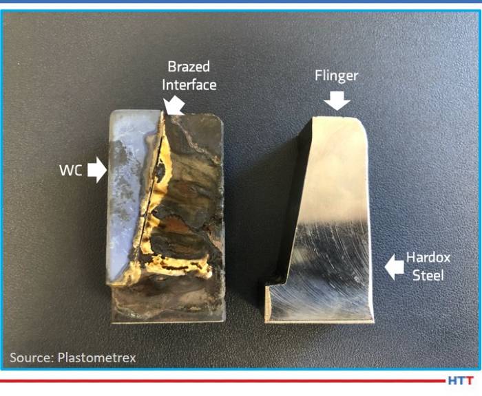
Photograph of the Hardox steel samples, with and without the WC insert attached, showing high levels of oxidation following from the brazing process. Source: Plastometrex
Mechanical testing is a standard production step in heat treating operations, but conventional methods of testing don’t always yield stress values consistent with the testing calculations.
Indentation plastometry allows users to obtain material strength characteristics in a way that is faster, cheaper, and simpler than conventional mechanical testing procedures. James Dean explores this novel mechanical testing method developed to infuse efficiency and accuracy into the process.
“The testing process is fully automated and involves three simple steps. The first is the creation of an indent using the indentation plastometer which is a custom-built, macromechanical test machine. The second is measurement of the residual profile shape using an integrated stylus profilometer.
“The third is the analysis of the profile shape in a proprietary software package called SEMPID, which converts the indentation test data into stress-strain curves that are comparable to those that would be measured using conventional mechanical testing methods. The entire procedure takes just a few minutes, and the surface preparation requirements are minimal.”
Stainless steel has crept into our kitchens and now also our garages, the Tesla Cybertruck being the latest product to sport a stainless steel layer. What most people don’t realize is that while stainless steel is corrosion resistant, it will rust in a lot of circumstances. In this Technical Tuesday article, Sarah Jordan explores how stainless steel can be compromised by improper heat treatment and the steps heat treaters can take to prevent corrosion.
This column was adapted from a #MetallurgyMonday post written by Sarah Jordan in June 2024 and shared at her LinkedIn account. It appeared as an article in Heat Treat Today’sAugust 2024 Automotive print edition.
I’m starting to see Cybertrucks out in the wild more, so I decided to talk about stainless corrosion for #MetallurgyMonday. (If you don’t know what #MetallurgyMonday is, it is a weekly educational post on metallurgy topics that I’ve been writing on LinkedIn for the past two years.)
First a little up front. I’m not a fan of the aesthetics of the Tesla Cybertruck. Plus, we need about twice the load capacity for our work purposes since Skuld actually uses our truck as a truck.
More to the point, stainless steel is not rust proof. It is corrosion resistant and will rust in a lot of circumstances.
To understand why, we need to understand what prevents corrosion in the first place. The key elements are chromium and nickel. Chromium reacts with oxygen to create a thin layer of chromium oxide. This is on the surface and blocks further oxidizing of the underlying layers. Meanwhile, the nickel enhances the corrosion resistance. It also makes the material more formable and weldable.
The short story is that if the chromium oxide layer gets compromised, stainless steel will corrode.
Improper heat treating can also contribute to stress corrosion cracking.
Sarah Jordan
Pitting corrosion: If you have a scratch or a pit, this can damage the protective film, and then corrosion begins. It’s worse in environments with chloride ions, such as seawater or pool water. Chlorides break down the passive layer, leading to rapid and severe corrosion in small areas.
Crevice corrosion: This occurs when two objects come together, especially things like fasteners or where there is a gasket. Inside the crevice you will have a lack of oxygen. The lack of oxygen prevents the reformation of the protective chromium oxide layer. Once corrosion gets started, it can get very severe by propagating in the crevice.
Stress corrosion cracking (SCC): Corrosion is made worse where there is a combined effect of tensile stress and a corrosive environment. It typically affects stainless steel used in structural applications that are exposed to chloride or sulfides. SCC can cause sudden and catastrophic failure of the metal structure.
Galvanic corrosion: Galvanic corrosion happens when two metals are put together. One of them almost always wants to preferentially corrode. The one that corrodes is the one that is higher on the galvanic series.
Intergranular corrosion (IGC): Sometimes this is called intergranular attack (IGA). In this case, corrosion occurs preferentially at grain boundaries. This can occur in stainless if the grain boundaries get depleted of chromium because a minimum amount is needed to ensure the passive film can form to protect the metal. When this occurs, there can also be localized galvanic corrosion.
Composition variation: If the composition has segregation, then there are some areas that have less of the corrosion-helping elements. And on top of that, galvanic corrosion can start happening within the material.
What does all of this have to do with heat treating? Improper heat treating can contribute to corrosion.
For instance, intergranular corrosion can be caused if the material is exposed to 842–1562°F (450–850°C) for too long as this will cause chromium carbide to form at the grain boundaries and deplete the chromium. This process is called “sensitization.” It is avoided by making sure quench rates are fast enough through the risky temperature range.
A somewhat similar situation can occur during heat treating if sigma phase forms in super duplex stainless steel. Sigma phase is an iron chromium phase which can also deplete the chromium.
Improper heat treating can also contribute to stress corrosion cracking. When material is quenched, it can cause residual stresses that, if not relieved, can become an issue.
Corrosion in stainless steel can often be traced to improper heat treatment. When stainless steel is heated between 842–1562°F (450–850°C), chromium carbides can form at the grain boundaries, depleting the surrounding areas of chromium and making them susceptible to corrosion.
All of this to say, things like the Cybertruck (or for that matter stainless fridges and appliances) can be prone to corrosion since they are exposed to a lot of abuse and aggressive environments. It is critical to ensure they are properly manufactured, including good heat treating practices. It is also critical to provide them with proper maintenance to keep the corrosion resistance and appearance lasting as long as possible.
About the Author:
Sarah Jordan Founder & CEO Skuld, LLC Source: Author
Sarah Jordan is an accomplished metallurgical engineer and entrepreneur. She received a bachelor’s of science and master’s of science in this discipline from The Ohio State University and has been pursuing a PhD in Metallurgical Engineering from WPI. Skuld is a certified WOSB and EDWOSB startup focused on 3D printing, advanced manufacturing, and advanced materials.
Get ready to watch, listen, and learn about the three most underrated heat treat processes in today’s episode. This conversation marks the continuation of Lunch & Learn, aHeat Treat Radio podcast series where an expert in the industry breaks down a heat treat fundamental with Doug Glenn, publisher of Heat Treat Today and host of the podcast, and the Heat Treat Today team.
Below, you can watch the video, listen to the podcast by clicking on the audio play button, or read an edited transcript.
The following transcript has been edited for your reading enjoyment.
Doug Glenn: There are some underdog heat treat processes out here. I’d like to get to three today. What do you think is number one?
Michael Mouilleseaux: Let’s start with stress relieving. All ferrous materials, all steels, during the course of manufacturing or processing, have some residual stress that is left in them. A common thought about stress relieving is you have a weldment, and you stress relieve it so that the weldment stays.
Contact us with your Reader Feedback!
There is a mechanical action in the material during any cold working operation (cold forging, stamping, fine planking, etc.) because it's done at ambient temperature. Those all impart stress on the part.
Machining, turning, grinding. . . all of those things impart stress into a part. How is that relieved? It can be done thermally, or it can also be done mechanically. Thermally is the most common of them.
What I would like to talk about is not so much stress relieving weldments, it is stress relieving manufactured components. If you’re going to have a comprehensive analysis of the heat treat operation that needs to be performed on a manufactured component, a gear, a shaft, something of that nature, they need to take into consideration what are the prior existing stresses in the part. Then what effect is that going to have on the part?
Many times during the course of my career, I’ve had a customer come to me and say, “The part I gave you was correct, and you’ve given it back to me and then fill-in-the-blank. It’s warped, it’s changed size, it’s shrunk, all of those things.” What have you done in your heat-treating process? You have to back up all the way to the beginning of how this part was manufactured and deal with all of those component steps in order to answer that question properly.
Stress relieving is one of the answers. It’s not the answer. It’s not the only answer, but it is one of them that has to be considered.
"Stress Relieving Tips from Heat TreatToday"
Doug Glenn: For those of us who might not know what a “stress” is in a part, can you simply explain? For example: a coat hanger. If I bend it, is that inducing stress? Is that what’s causing stress? What makes stress in a part?
Michael Mouilleseaux: You’ve cold-worked the part. In the cold working, you’ve passed the yield strength. You’ve bent it, and it’s not going to snap back. You’ve cold-worked it enough that you’ve actually got plastic deformation, and there is stress.
Doug Glenn: That’s one way we get stress. That’s the mechanical way of getting stress.
Michael Mouilleseaux: Right. Now, consider stamping. Even though a stamping is flat (because the die has come down in the perimeter of that and maybe internal holes and things), where you’ve sheared the material, you’ve imparted stress there.
If you harden it or case harden it or whatever you might do with that stamping, you have to take into consideration how much stress is there. If I don’t relieve it, is it going to do that at some point in the part’s future that’s going to be detrimental to the part?
Doug Glenn: When you get a stress in a part, that’s the area that’s a weak spot, right? It potentially could break before other parts?
Michael Mouilleseaux: At the absolute extreme, that could happen, yes. More often than not, what you have is an area that’s been cold worked, and it’s been deformed. When it stresses, it’s going to somewhat relieve itself. It may not relieve itself 100% all the way, but it will somewhat relieve itself. Whatever shape of form you’ve put that part into; it’s not going to hold that form forever.
Alyssa Bootsma: You mentioned that stress relieving is not the only way to alleviate the problems. What would be some alternatives to stress relieving?
Michael Mouilleseaux: Thermal stress relieving is, by far, the most common. There is a process that’s called vibratory stress relieving. In order to relieve the stresses in a part, you have to impart some energy in it. Something between 800 and 1200 Fahrenheit is typically used in stress relieving. That thermal energy goes into the part and relieves the stresses.
You could also do that mechanically by a high frequency vibration. It’s not as common. I believe that it’s actually a propriety process, if not patented. It would be for something that you did not want to subject to 800-1000 degrees Fahrenheit because that doesn’t come for free. Obviously, in a ferrous material at that temperature, you’re going to have some oxide forming on the part. You may or may not be able to utilize the part in its final function with that oxide on it.
Those are typically the two ways to do it. Can it occur naturally over time? Yes, but none of us have that kind of time.
Alyssa Bootsma: You did mention how it doesn’t necessarily mean that it’s more likely to break if that part is not relieved, but what parts would suffer the most if this process was done incorrectly?
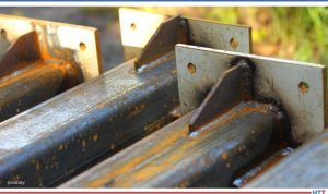
Michael Mouilleseaux: Probably weldments. The detrimental effects of not having stress relieved of weldment would be the most significant. In welding there is a whole range of temperatures proximate to the weld — everything from room temperature to maybe 3000 degrees. That whole range of things changes the structure of the steel.
Leaving it in that condition makes it susceptible to any number of things — embrittlement, accelerated corrosion, and others. There is every reason to stress relieve something like that and almost no reason not to.
Doug Glenn: That’s weldment. Do they do a stress relieve after a braze as well, or is that not as common?
Michael Mouilleseaux: Typically not. The reason for that is, in brazing, the entire assembly is brought up to the same temperature. Then it’s cooled at the same rate.
Bethany Leone: I have two brief questions: 1. How long does stress relieving typically take? 2. Would we see the effects of incorrect stress relieving, or failure to, once something goes to quench?
Michael Mouilleseaux: The first question — would you necessarily see a failure? Those would be extremes. I’m more familiar with stress relieving fabricated components that are machined. Take a gear. They forge a blank and maybe machine out the center of the gear, machine the exterior of the gear, cut the teeth in a shaping operation (a hobbing operation or skiving or other ways of generating teeth).
"You have this part, and it needs to be heat treated. To assume that all of those machining operations would have no effect upon that whatsoever is not a good thought."
Then comes a comprehensive program of evaluating how best to heat treat a part. It doesn’t matter if it’s out of a medium carbon alloy steel or it’s a low alloy steel and we’re going to carburize it, what’s critical is that it’s going to get heated. The material is going to transform into austenite and cool rapidly or quench it. That’s what’s going to cause the hardening operation on the part.
In doing that, there are going to be changes in size. In hardening a part, you get a volumetric expansion. Thin sections are not going to expand as much as larger sections. A misnomer is, “You shrunk the hole.” You haven’t shrunk the hole! The material around the hole has expanded, the exterior portion of that area has increased, and the interior portion of that has decreased.
If you have a spline in that hole, now you’re on for something else because their teeth form in that spline. If it’s in a long section, then how uniform it’s been hardened has to do with whether or not it goes out of round or their taper. There are any number of things there. Those are all critical to the operation of this gear.
But what we have to take into consideration is the broaching operation. We drill a hole, and we put a broach bar through it and cut all of these teeth. All of that has imparted stress in the part.
One of the preliminary things that needs to be done is you stress relieve the part and give it back to the manufacturer. They measure it and say, “Oh, oh, it changed!” That change is not something the heat treater can do anything about. That’s the physics of what happens when you work-harden a part. This all has to be taken into consideration and addressed before we talk about what’s the heat treat distortion.
Bethany Leone: And the other question I had: How long does it take to stress relieve?
Michael Mouilleseaux: Typically, if it’s held at an hour or two at temperature, it’s thought that 1000 degrees for an hour at temperature will relieve most stresses.
Now, in a component part, we’re going to go higher in temperature. Although we’re not going to go high enough to austenitize the part, we’re going to go high enough in temperature that we know we’re going to relieve it.
Michael Mouilleseaux: They’re cousins. Stress relieving, the implication is that you are doing that simply to relieve prior existing stresses. In annealing, the implication is that you are going to reduce the hardness of the microstructure for the purposes of machining or forming. In annealing, there’s subcritical and supercritical and a hundred different flavors of that.
Doug Glenn: I’m trying to get a sense of what percentage of heat treating is stress relieving. Is it super popular? It seems to me it would be very common.
Michael Mouilleseaux: Interestingly enough, I’m going to say that the majority of the gearing product that we do, we incorporate a stress relief in the initial stages of heat treating. By putting the part in and raising the temperature to a stress relieving temperature and then taking it up into the austenitizing temperature, you’re not shocking the part. You’re not just taking it from room temperature to carburizing temperature or hardening temperature, and thereby you’re reducing the thermal stresses. So, you’re not imparting any more.
Doug Glenn: Stress relieving may often be done as a part of another process?
Michael Mouilleseaux: It can be, definitely.
Doug Glenn: Let’s move on to the second forgotten heat treatment.
Michael Mouilleseaux: I don’t know about forgotten. I’m going to say that it’s getting short shrift, and that is conventional atmosphere carburizing. What’s sexy in heat treating? It’s low pressure carburizing and gas quenching. It’s growing very rapidly and it’s being used in a lot of applications.
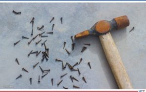
We’re subject to the same ills that Mark Twain identified years ago, and that is, “To a man with a hammer, every problem looks like a nail.” Low pressure carburizing and gas quenching, they can save every distortion issue that’s ever been known to man in heat treating, and they don’t. They are other tools in the box, applicable to a lot of application. They are great processes, very targeted and specific. You know, sometimes you need a screwdriver instead of a hammer.
Conventional carburizing: It’s been around for a hundred years. What’s different today than what it ever was? Certainly it has everything to do with the control systems that are being used to control it. It’s eminently more controllable now than it has ever been. It is a precision operation, and it has many applications. By the way, it’s far more cost effective than carburizing would be. In vacuum carburizing, the cost is multiple; is it two, three or four times more expensive? It depends on how you calculate cost of capital and all of those things. But it’s a multiple, more expensive than conventional carburizing.
Doug Glenn: To do vacuum carburizing?
Michael Mouilleseaux: To do vacuum carburizing, yes. Should it be used in every application? I’m going to say no. Are there definite applications? Definitely.
Doug Glenn: Conventional carburizing, atmosphere carburizing is another area largely forgotten. I know it’s quite popular, but it’s not getting a lot of discussion these days.
Michael Mouilleseaux: Right. Any time there is an issue with a carburized part, everyone knows to ask the question, “Why don’t you vacuum carburize it?” The answer to that is, “Let’s solve the problem before we decide what it is that we need to do.”
Karen Gantzer: Mike: At a very basic level, can you explain why do heat treaters use endothermic gas?
Michael Mouilleseaux: In atmosphere carburizing, we need a method of conveying carbon to the part so that we can enrich it; that’s what carburizing is. The carburizing portion of the atmosphere in endothermic gas is carbon monoxide. Carbon monoxide — that’s the reaction at the surface of the part — the carbon diffuses into the part. That’s how you generate a case in the part.
It’s a relatively inexpensive form of carburizing. You use natural gas and air in what we call a “generator”, and that’s how endothermic gas is generated. Then, it’s put into the furnace. There’s almost no air in a furnace. People think you’re going to look in a furnace, and you’re going to see flame. You never do because the amount of oxygen in the furnace is measured in parts per million. You put additional natural gas to boost the carburizing potential of the atmosphere, and that’s what allows you to diffuse carbon into the part. That is the case hardening process.
Doug Glenn: Conventional carburizing is done in a protective atmosphere, typically as an endothermic atmosphere which is rich in carbon monoxide.
Michael Mouilleseaux: Yes.
Doug Glenn: A lot of times we’re worried about oxygen in the process because of potential oxidation. Why is it that we use a gas that has oxygen in it to infuse carbon? I know it’s got carbon, but it’s also one C and one O, right? Don’t we run into problems of potential oxidation?
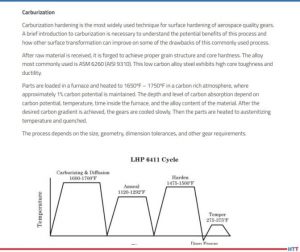
"Comparative Study of Carburizing vs. Induction Hardening of Gears"
Michael Mouilleseaux: In endothermic gas there is hydrogen, nitrogen and carbon monoxide, and there are fractional percentages of carbon dioxide and some other things. The hydrogen is what scrubs the part; that’s what kind of takes care of all of the excess oxygen. The nitrogen is just a carrier portion of it, and the carbon monoxide is what is the active ingredient, if you will, in the carburizing process.
The carbon diffuses into the part. If there is an oxygen, it’s going to combine with the hydrogen. Preferentially, you’re not going to have any free oxygen in the furnace, but you can have a little water vapor. One of the ways of measuring the carbon potential in the furnace is a dewpoint meter. The dewpoint meter is measuring the temperature at which the gas precipitates out, and that’s a monitor or a measure of the carbon potential.
Doug Glenn: A dewpoint analyzer helps you know what the carbon potential is.
Michael Mouilleseaux: Yes. It’s not as good as an oxygen analyzer.
Doug Glenn: An oxygen probe.
Michael Mouilleseaux: The oxygen probe is in the furnace, measuring constantly. You get a picture; you have continuous information. It’s not that there aren’t continuous dewpoint analyzers, but you have to take a sample from the furnace. It has to be taken to an analyzer wherein it is then tested. Best case scenario is you have both of them and you compare the two of them. That gives you a really great picture of what the atmosphere conditions are in the furnace.
Alyssa Bootsma: For a bit of background knowledge: What is the difference between endothermic gas and exothermic gas?
Michael Mouilleseaux: Endothermic gas has 40% hydrogen and 20% carbon monoxide. 60% of it is what you would call a reducing atmosphere. The way that you make endothermic atmosphere is 2.7 parts of natural gas and one part of air. You heat it up to 1900 degrees, and it’s put through a nickel catalyst. You strip off the hydrogens. The gas dissociates, and that’s what results.
Exothermic gas is six parts of air in one part of natural gas. You only have 10 or 15% hydrogen. Although it’s not an oxidizing atmosphere, it’s very mildly reducing.
It can be used in annealing, clean annealing. If you’re annealing at 12-1300 degrees or more or in that ballpark, that kind of an atmosphere is going to keep the work clean. If you did it in air, it would scale.
Bethany Leone: Is there an industry (automotive, aerospace, energy) that it would be most helpful for those parts to be typically atmosphere carburized, and/or is it just generally helpful for all types of industries?
Michael Mouilleseaux: First of all, the transportation industry is the lion’s share of heat treating — automotive, truck, aircraft. Atmosphere carburizing is extremely popular and commonplace in those industries.
If we said that we were going to have a seminar and I’m going to talk about atmosphere carburizing. Somebody else is going to talk about low pressure carburizing in a vacuum furnace. Everybody’s going to go over to the other room. Folks feel they already know what this is all about, and they know what all the problems are. They think that the vacuum carburizing is going to solve all of them.
When you work with the proper kinds of controls, the proper kinds of furnace conditions, the right way of fixturing parts and cleaning them ahead of time, you can have extremely consistent results. You can have extremely clean parts, and you can have very good performance from these things.
What the Europeans call “serial production”: we run millions of gears per year, and we have very consistent case steps in hardnesses as a result of good practice. All of these things need to be monitored and controlled and taken care of. But the results are also very consistent and very predictable.
Doug Glenn: Interesting. And it’s more cost-effective, I’m guessing. Conventional atmosphere carburizing, on a per part basis, is going to be substantially less expensive.
Michael Mouilleseaux: We’ve looked at it. Is it two times, is it three times, is it four times more expensive to vacuum carburize a part? The answer is yes. The question is, does that component justify that? There are any number of them where it does.
Doug Glenn: Where it does justify it?
Michael Mouilleseaux: Yes, absolutely.
Doug Glenn: Let’s go on to #3, the third underdog in heat treating.
Michael Mouilleseaux: Number three is marquenching. Marquenching, martempering, and hot oil quenching are in the family that describes this process.
Martempering is different than just quenching in oil, quenching in regular fast oil. Regular oil is going to be 100 vis, and it’s going to be from 90 degrees to 150 degrees. All kinds of low hardenability, or parts that don’t have a lot of adherent alloy in them, you utilize that so that they can be fully hardened. But components that are distortion-critical, quenched in that manner in regular oil, there is going to be a high degree of distortion. How is that addressed? It’s addressed in marquenching.
Let’s take an example of a carburized gear. A carburized case is heated to 16-1700 degrees and carburized. Best practice would say that I’m going to reduce the temperature before I quench it, and then I’m going to quench it in oil. Do I understand that: I have to have loading that spaces the part; and the parts need to be fixtured in such a way that, physically, they don’t impede on each other; and I get full flow of oil, and all of those things? The answer is yes, yes, and yes.
The martensite starts to form in the case at, let’s say, 450 and it’s plus or minus 25 or 30 degrees or so. Take that part and put it into the range where the martensite starts to form, and hold it at that temperature and let the entire part cool down to that 450 degrees where the martensite is starting to form. Then we remove the part from the furnace and allow it to cool in air to room temperature. At that point, the cooling rate is much lower than it it’s going to be where you’re conducting that in a liquid medium. Because of that, the stresses are going to be less, the distortion is going to be less. That is a strategy for reducing distortion.
You ask, “Why do you need to do that.?” Again, the man with the hammer: I’m going to gas quench this part because I have the opportunity to gas quench it, and the gas quenching doesn’t come for free. The shadowing effects of a gas flow has to be taken into consideration, orientation of the parts. There are a number of things that need to be taken into consideration.[blocktext align="left"]There are a number of applications where in marquenching a part, the distortion can be controlled. We process a lot of gears, and we maintain 20/30 microns of total distortion in ID bores on gears. It is a viable way of controlling distortion.[/blocktext]
Doug Glenn: We say marquenching.
Mike Mouilleseaux: Or martempering or hot oil quenching.
Doug Glenn: The “mar” part of that comes from martensite? I want have you explain what exactly martensite is. But is that where it comes from?
Mike Mouilleseaux: Yes. We’re getting right into the start of the martensite transformation.
Doug Glenn: There are different microstructures in metals. Austenite is pretty much the highest temperature, and it’s where the molecules are almost “free floating.” They’re not liquid, but they can move around. (This is very layman’s terms.) That’s austenite.
What causes distortion is when you’re cooling from austenite down to the point where that thing is, kind of, locked in; that can cause distortion in there because the molecules are still free to move. Some areas cool faster than others, and when you have that, you can get twists and turns or bulges. Once it gets down to the martensite temperature, that’s when things are, locked in. Is that fair?
Michael Mouilleseaux: The other thing that happens is you’re going from a cubic structure to a tetragonal structure. You’re asking, “Why are we there?” That’s where the expansion comes. The close-packed tetragonal structure takes up more volume than the austenitic or cubic structure. That’s where the volumetric expansion takes place.
Doug Glenn: At a higher temperature, the molecules are arranged in such a way that they take up more space; there’s more space between them.
In the cooling process with marquenching, if you bring it down just to the point where it’s, what Mike referred to as, the ‘martensite start temperature,’ that’s the temperature where things are just locking in. But it’s not so drastic that you’re dropping way down in temperature so that there are larger temperature differentials and things are really starting to get torqued out of contortion because of the difference in the cooling rates in the part.
Michael Mouilleseaux: The other part of that is that the formation of martensite is not time dependent. It’s not like you would have to hold it at 400 degrees for a longer period of time than you would at 200 degrees to get martensite. At 400 degrees, you’ve got some percentage of transformation. Say, it’s 30%. The transformation is temperature dependent. Because it’s temperature dependent, you can take it out and slow down the cooling rate. Then, as the transformation takes place, there is less stress, and if there’s less stress, then there is less distortion.
Again, it’s typically going to be distortion-sensitive parts.
The simplest geometric shape is a sphere. There aren’t any changes in section size in a sphere. It can be rotated, and you’ve got the same section size. You don’t have the kind of thing where one area is cooling more rapidly than another.
A major source of distortion is varying mass. Like a hole in a block: one portion of the block is two inches wide, and another portion is an inch wide. To think that that hole is going to stay straight all by itself, that won’t happen because there’s more mass around one end. By marquenching it and slowing down the transformation, you’re giving yourself an opportunity to reduce the amount of stress that’s generated. It’s the volumetric expansion in the thicker section than in the thinner section. Your opportunity to maintain that hole so that it stays round and it stays straight is much better. Otherwise, the thin section is going to completely transform before the thicker section does.
Doug Glenn: Transform to martensite or whatever, yes.
Michael Mouilleseaux: The extreme case in that is if that happens rapidly enough, and there’s a large enough differential in section size, the part cracks.
Doug Glenn: That’s the nightmare for the heat treater.
Guest Michael Mouilleseaux with the Heat TreatToday team
Bethany Leone: Are there any instances where it’s definite that another way to manage distortion would be better than marquenching?
Michael Mouilleseaux: Sure. Again, what’s currently sexy in this industry is gas quenching things. I’m going to say that cylindrical parts that have a thin wall, when properly gas quenched, will give you better distortion control, better size control than it would if you’d quench them in a liquid medium such as oil. We don’t want to forget that marquenching can be performed in salt, as well.
If we were going to talk about a fourth one, it might be salt quenching because that’s one of those things that’s not commonly utilized. There is some real opportunity with it.
Doug Glenn: Mike, thanks for ‘dumbing this down’ for us. We appreciate it! It’s sometimes a struggle to state things simply, but you did a great job.
Are there any closing thoughts you’d like to leave with us regarding the nearly-forgotten, popular heat treat processes, or anything else?
Michael Mouilleseaux: How about the combination of all three that I just spoke about?
Doug Glenn: Okay. Well, how about that?
Michael Mouilleseaux: I’ve got a distortion sensitive gear, and we’ve figured out that there is some stress in the part as a result of the final machining operation. We stress relieve the part, we carburize it conventionally, and then we marquench it. Those gears that I spoke about where we’ve got 20 or 30 microns of ID bore distortion — that’s exactly what’s done there.
Doug Glenn: Okay. Stress relieve first, conventional carburize, and then marquench. A combination of three.
Mike, thank you very much. This has been really helpful and it’s been good to learn a little bit on our Lunch &Learn. We’ll hope to have you back sometime to make other things understandable for us.
About the expert: Michael Mouilleseaux is general manager at Erie Steel LTD. Mike has been at Erie Steel in Toledo, OH since 2006 with previous metallurgical experience at New Process Gear in Syracuse, NY and as the Director of Technology in Marketing at FPM Heat Treating LLC in Elk Grove, IL. Having graduated from the University of Michigan with a degree in Metallurgical Engineering, Mike has proved his expertise in the field of heat treat, co-presenting at the 2019 Heat Treat show and currently serving on the Board of Trustees at the Metal Treating Institute.
Stress relieving tips from Heat TreatToday? It's not what you think! In this Technical Tuesday, we'll be sharing some fast facts you need to know about stress relieving. It may not be as relaxing as some guided meditation, but at least you will walk away with a refreshed knowledge of stress relieving, a new technology for measuring material stress, and a video demonstration of the stress/strain curve.
Stress Relieving Fast Facts
What is stress relieving? In the most basic sense, stress relieving is heating a metal to a relatively low
Dan Herring "The Heat Treat Doctor" The HERRING GROUP, Inc.
temperature and then slowly cooling it to reduce the affect of manufacturing-induced stresses.
Why do heat treated parts need to be stress relieved? Manufacturing processes (forging, shearing, bending, etc.) introduce internal stresses, and these stresses, if left unaddressed, can cause the finished part to fail in its end application.
Thermal stress relieving is the preferred method of stress relieving, but mechanical stress relieving is also an option. Vibratory stress relieving and shot peening are two mechanical stress relieving methods available to heat treaters.
Want more fast facts? Check out Dan Herring, The Heat Treat Doctor's®, Atmosphere Heat Treatment, Volume 1.
Addressing Stresses: Indentation Plastometry
James Dean CEO Plastometrex
Stresses introduced during the heat treating process must be addressed. Failing to address these stresses can be disastrous. Mechanical testing systems are crucial in ensuring heat treating had its desired effect and that no new stresses have been introduced to the material. As most heat treaters know, the stress/strain curve of materials is often a give and take. To get high strength, you often have to give up ductility. Measuring the extent of these trade-offs — and measuring plasticity and strength characteristics in general — after heat treating can be time consuming.
In this episode of Heat TreatRadio, James Dean of Plastometrex explains a new technology, indentation plastometry, that measures microscopic stresses in heat treated material. These stresses can affect the yield point of a material and the point of plastic deformation. What's even better is that, with indentation plastometry, heat treaters can view stress/strain curves in minutes and know if there is a need for further stress relieving.
A Refresher on the Stress/Strain Curve
Need a refresher on the stress/strain curve after hearing from James Dean? Check out this episode of Heat TreatTV.
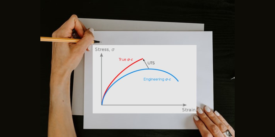
The stress/strain curve is "metallurgy basics." If you spend any amount of time in the heat treating world, this graph will be a familiar sight to you. Basic though it may be, a refresher it always a good idea. Just how much stress can a material withstand before breaking? How does heat treating affect the yield point of different materials?
Find heat treating products and services when you search on Heat Treat Buyers Guide.com
Innovation. New processes to help efficiency and accuracy. Who doesn’t like to hear about ways to improve production on a Technical Tuesday? Check out how this novel mechanical testing method is gaining traction.
This original content article was written by James Dean, CEO of Plastometrex, for Heat TreatToday'sMarch 2021 Aerospace print edition. Feel free to contact Karen Gantzer at karen@heattreattoday.com if you have a question, comment, or any editorial contribution you'd like to submit.
James Dean CEO Plastometrex
Plastometrex is a start-up based in the United Kingdom that is commercializing a novel mechanical testing method called indentation plastometry. The technique – developed over a ten-year period of research at the University of Cambridge – allows users to obtain material strength characteristics (full stress-strain curves) in a way that is faster, cheaper, and simpler than conventional mechanical testing procedures.
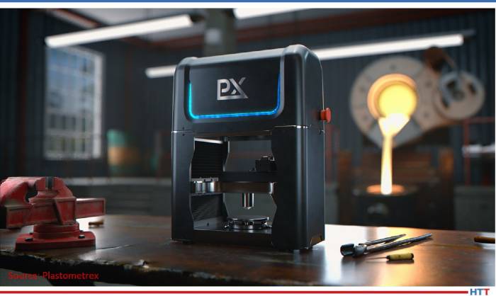
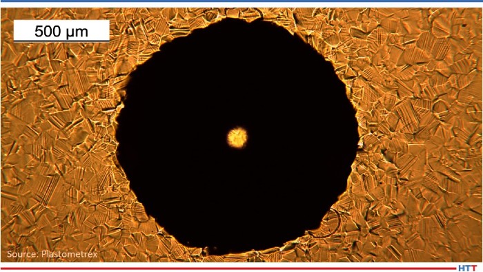
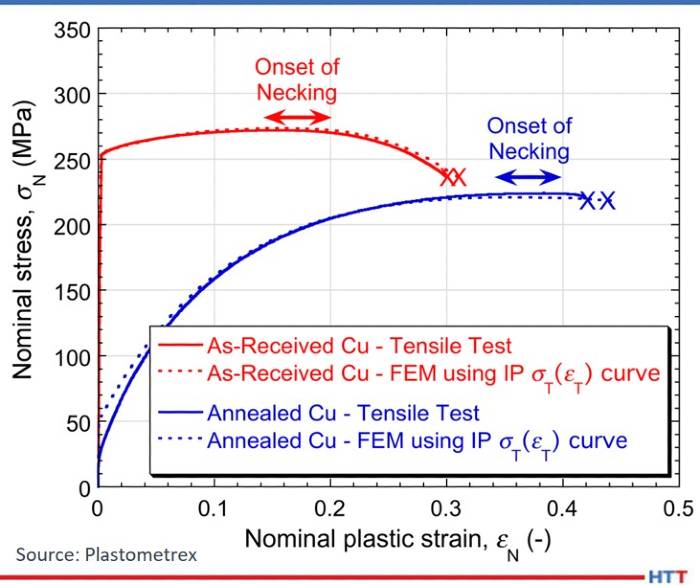
The testing process is fully automated and involves three simple steps. The first is the creation of an indent using the indentation plastometer which is a custom-built, macromechanical test machine (Figure 1). The second is measurement of the residual profile shape using an integrated stylus profilometer (Figure 2). The third is the analysis of the profile shape in a proprietary software package called SEMPID, which converts the indentation test data into stress-strain curves that are comparable to those that would be measured using conventional mechanical testing methods (Figure 3). The entire procedure takes just a few minutes, and the surface preparation requirements are minimal.
Another advantage over conventional tensile testing is the ability to map spatial variations in mechanical properties as well as the ability to test real components. In fact, in a recent project conducted in collaboration with Energy Densification Systems, a South African company servicing the mining industry, an indentation plastometer was used to characterize the change in stress-strain behavior that took place within a Hardox steel component subjected to high temperature during a brazing process.
Figure 1. The Indentation Plastometer from Plastometrex.
Figure 2. A residual indent after indenting a steel sample with the Indentation Plastometer, showing local grain structure.
Figure 3. Comparisons between stress-strain curves obtained using indentation plastometry, and stress-strain curves obtained using conventional tensile testing on specimens of copper in as-received and annealed conditions.
One of the Hardox steel samples (Figure 4) has a tungsten carbide (WC) insert that is brazed to the front surface, and this is clear evidence of a high temperature event having taken place here (from the presence of oxidation). The other sample is in its as received form. The objective of the tests was to determine if the high temperature brazing process had in any way affected the mechanical properties of the Hardox steel and, if so, to quantify the results.
Figure 4. Photograph of the Hardox steel samples, with and without the WC insert attached, showing high levels of oxidation following from the brazing process.
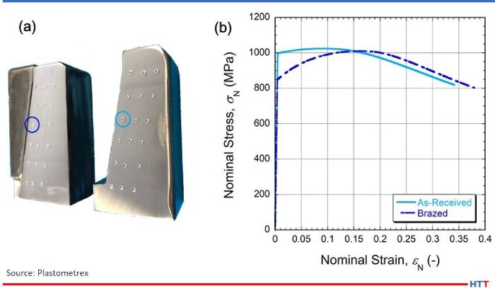
The oxidized layer was then removed and the Hardox steel samples were indented in the locations that are shown in Figure 5a. The indentation data were analyzed and converted into stress-strain curves using the SEMPID software. Two are shown in Figure 5b, where it is apparent that the high temperature brazing process has affected the strength characteristics of the material in that location.
Figure 5. (a) Photograph of the Hardox steel samples after indentation testing and (b) indentation-derived stress-strain curves from the locations identified in (a).
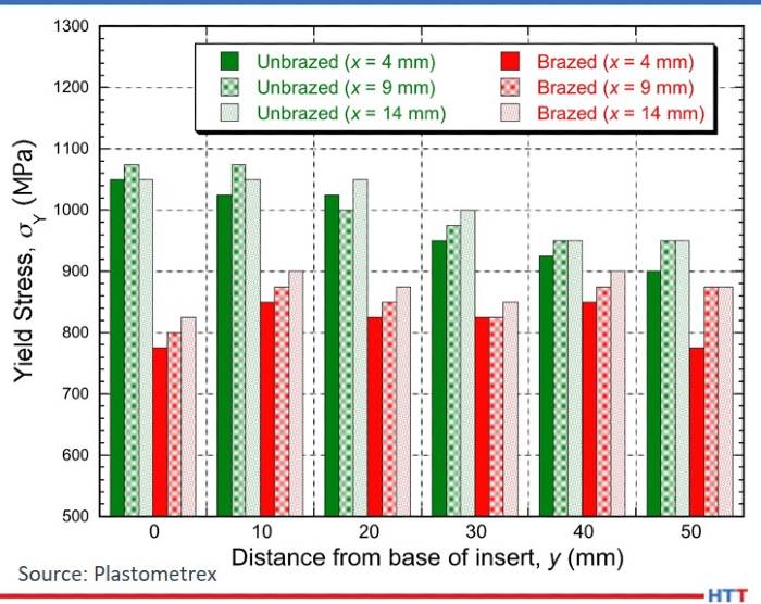
Further data are provided in Figure 6, which compares the indentation-derived yield stress values across the two specimens. This data demonstrates that the yield stress is substantially lower in the specimen that was subjected to high temperature during the brazing process. Importantly, these yield stress values, which could not have been obtained using conventional mechanical testing procedures, could subsequently be used in calculations that predict the wear lifetime of these components, which form part of the apparatus inside a rock comminution device.
Figure 6. Bar chart showing indentation-derived yield stress values as a function of location, with y being the distance along the brazed interface and x the distance from it, for the as-received substrate and for the brazed assembly.
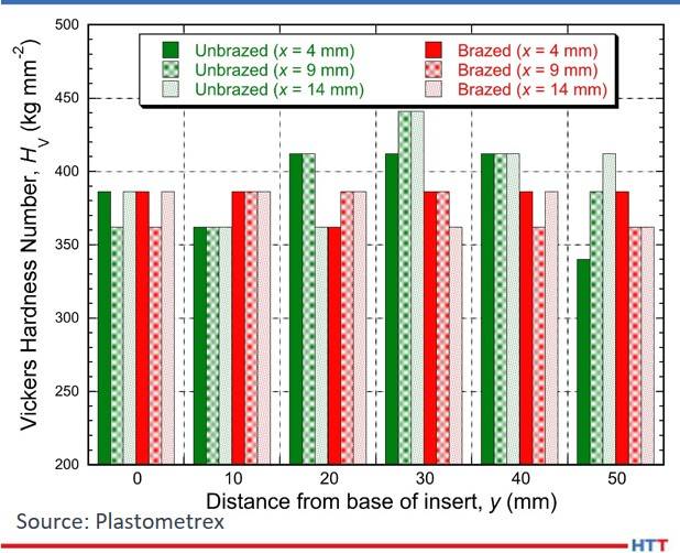
One further aspect worth highlighting was the inadequacy of conventional hardness numbers to detect or systematically characterize these changes. Figure 7 plots the Vickers Hardness numbers (at 5 kg load) for the two steel specimens in the as-received and heat-affected conditions. It can be seen that the outcome is more vague and confusing than it was for the yield stress values, suggesting that indentation plastometry offers access to superior and more valuable data than conventional hardness test machines.
Figure 7. Vickers hardness numbers corresponding to the locations where indentation plastometry was carried out. The applied load was 5 kg.
About the Author: James Dean is the CEO of Plastometrex and has an undergraduate degree in materials science, a masters in gas turbine engineering, and a PhD in materials science from Cambridge University, where he subsequently held research assistant and senior research associate positions. He also helped manage the Centre for Doctoral Training in Computational Methods for Materials Science at Cambridge. He co-founded Plastometrex in 2018. For More Information: Contact James at j.dean@plastometrex.com
Heat treating plays a critical role in the making of a mold base, notes an Austrian manufacturer of standard parts for mould bases and die sets in a recent process profile in ETMM-online.
An excerpt:
"Heat-treat[ing] all steel plates for stress relief . . . at approximately 580°C [1076°F] for 24 hours . . . creates optimal conditions for low-deformation processing of parts. . . . With stress-relieving heat treatment, the tension in the material is minimized without changes to the microstructure or strength. This is a great advantage during subsequent machining. If there was still tension in the material, it would, for example, cause deformation during sawing or milling. During stress-relieving, it is important to heat the plates slowly and consistently and then maintain this temperature for six hours."
“Vacuum heat treatment tasks for AM manufactured parts is the same process as traditional subtractive manufacturing and its purpose is to assure AM parts has the correct physical and metallurgical properties for specific applications. In some cases, when a bidder is involved, the purpose of the heat treatment process is to deciding and sinter parts. Most vacuum furnaces use up to 800°C degrees to relieve stress and a higher temperature of up to 1800°C for other processes.
Vacuum furnaces with high vacuum levels are preferred to heat treatment equipment to process AM parts. AM parts made from Titanium, Cobalt, Aluminum require vacuum levels of up to 10-6 mbar with 99.9995 Argon purity. Argon is the preferred gas because of its neutrality and that it has no adverse reaction with the above alloy components. Creating an Alfa surface layer on titanium parts is not desirable and should be avoided.
The small parts and small production volume influences vacuum furnaces of small to medium size. The next challenge for the heat treatment industry is to integrate heat treatment process into the AM equipment in one continuous process.”