Batch or continuous — which equipment is better for your operations? Today’s Heat Treat Radio episode is a lunch & learn to answer your burning question about batch IQ vs. continuous pusher furnace systems. Michael Mouilleseaux of Erie Steel is a boots-on-the-ground expert in North American heat treat, and he’ll share a bit about the history of these systems before getting into the equipment and heat treat processing differences.
Doug Glenn, Heat Treat Today's publisher and the Heat Treat Radio host, Karen Gantzer, associate publisher/editor-in-chief, and Bethany Leone join this Heat Treat Today lunch & learn.
Below, you can watch the video, listen to the podcast by clicking on the audio play button, or read an edited transcript.


HTT · Heat Treat Radio #102: Lunch & Learn, Batch IQ vs. Continuous Pusher Systems Part 1
The following transcript has been edited for your reading enjoyment.
The History of Batch and Pusher Furnaces (00:52)

DOUG GLENN: Can you talk with us a little bit about the whole history of batch furnace versus pusher furnace?
MICHAEL MOUILLESEAUX: Sure. And thank you for having me!
Interestingly enough, the pusher furnace — which we might say is a more complex piece of equipment than a batch integral quench furnace — preceded the batch furnace. Atmosphere pushers were around prior to World War II. I spoke with a number of folks in the industry and asked, “How could that possibly be, given the level of complexity?” Interestingly, pushers were available because the atmosphere was generated by a charcoal generator.
If you think back to pack carburizing, we used charcoal and some accelerator. You would put it in a closed container, you’d heat it up, and that’s how you carburized things before you had atmosphere furnaces. Utilizing that same concept, they generated an atmosphere, put it in a furnace, and pushers were the first ones to do that.
So, who were the folks who did that? They were AFC-Holcroft, Surface Combustion, and Ipsen, all the usual characters and suspects there.
Pusher furnaces were available in single row and multiple row configurations.
They were heated with gas or electricity. I have to think that the earlier ones were heated by gas. Typically, they employed oil quenching. Although atmosphere cooling could be in the works, to find something of that vintage is very difficult. Maybe someone listening to this will weigh in and say, “Well, let me help you with that.”
The batch integral quench furnace is post World War II. What precipitated the development of the batch integral quench furnace was the development of the atmosphere generator, and that’s thanks to and around 1941 he actually published a book on atmosphere generators. I’m not sure where to find documentation of the patent he was granted for this generator. It might be interesting to discover. But again, Lindberg, Surface, Ipsen, — all these folks had these furnaces in the late 40s/early 50s.
When they started out, these furnaces were relatively small. The furnace might have had a tray that was 12 inches x 12 inches x 8 inches tall. You’d struggle to fit a hundred pounds into something like that.
But the batch furnace is by far the most popular atmosphere furnace that is available. You’ve got a variety of processing capabilities, which makes very flexible. There are a wide variety of sizes, even today; it can be heated with electricity or gas (we’ll talk about that a little bit later). You can have an oil quench furnace, you can use a polymer quench, and you can have a furnace where you atmosphere-cooled the load after it was processed in the primary furnace.
During this discussion, I’m going to use “batch,” “batch IQ,” and “batch integral quench” semi-interchangeably. So, if I say “batch” and I forget the “IQ” or if I say “batch integral quench” — these are all the same pieces of equipment. We have numerous names for the same thing.
DOUG GLENN: Gotcha. You said the continuous furnace came first because the atmosphere was being created by burning charcoal inside the furnace, that created a carbon rich environment?
MICHAEL MOUILLESEAUX: Actually, it was a generator that was pumped into the furnace.
DOUG GLENN: Got it. That was confusing; I was wondering how they were burning charcoal inside a furnace.
MICHAEL MOUILLESEAUX: Actually, it was explained to me that because the pusher furnace was so much larger, when you would open the doors to place or extract a load, the relative pressure drop of opening a door wasn’t that great. So, these primitive charcoal generators could accommodate that.
But in a batch furnace, arguably, the door is one wall of the furnace, and you couldn’t create a sufficient amount of pressure in the furnace. So, it had to wait until we had endothermic generators so that we could establish a furnace pressure higher than atmospheric pressure to make batch furnaces. It’s fascinating.
Basics of the Batch Furnace (05:41)
DOUG GLENN: And as you said, it is probably the most popular furnace used today by many, many heat treaters. Let’s talk about batch furnaces, here we go.
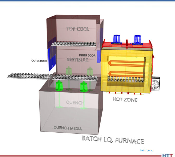
MICHAEL MOUILLESEAUX: Let’s look at the CAD drawing for a batch furnace. The batch furnace is primarily two components. You can see the hot zone — that is the furnace proper. It’s highly insulated, it has radiant tubes in it (so we can put atmosphere in the furnace), and the heating portion does not affect the atmosphere.
It is loaded through a vestibule, and the vestibule is pressurized as well. A load can go into a vestibule, you can close the door, you open the inner door, the load goes into the furnace, you can process it and then, as you can see, you can either quench the load or you can top cool the load.
Common Processes in a Batch Furnace (06:31)
What kind of things can we do in an atmosphere furnace? Answer: operations that do not require quenching. We could stress relieve, we could subcritically anneal, we could supercritically anneal (so, above and below 1350/1400 Fahrenheit), and then we can normalize.
Normalizing is utilized for products like forgings or castings which are made at a very high temperature. You’ve got a number of structures in the component and what you want is a “normal” structure. You want a uniform structure throughout the part so that it can be machined.
Normalizing is typically performed at a high temperature, and it’s put into this top cooled/atmosphere cooled chamber. In the old days, that was termed “air cooling” — it was a rate equivalent if you just set it out in air. These top cooled chambers are somewhat insulated; they have cooling jackets that are in the side, and there is a fan in them so you can circulate the atmosphere through it so that you get uniform cooling throughout the load.
DOUG GLENN: Michael, this isn’t considered high pressure gas quenching though, right?
MICHAEL MOUILLESEAUX: Not even close.
In this animation, we have the load going into the furnace, the vestibule door closes, the furnace door opens, the furnace door closes, we perform whatever process we want, we extract the load out of the furnace, and it goes up into the top cool chamber. It’s then atmosphere cooled. When that is completed, we take the load out.
The time in the furnace could be four hours (plus or minus). The time up in the top cool chamber would probably be an hour or two. Once the load is extracted from the furnace and is put into the top cool chamber, and you reestablish pressure in the vestibule, you actually open the outer door, put another load in and start processing the next load while the initial load is being cooled.
Then, there are processes that require quenching. In degree of simplicity, first there is neutral hardening. Neutral hardening implies that the atmosphere in the furnace is neutral with the carbon content of the steel. So, for a 30-carbon steel, you’d want a 30-carbon atmosphere; for a 40-carbon steel, you’d want a 40-carbon atmosphere. The optimum is to neither enrich nor to deplete the surface carbon; you don’t want to change the chemistry. Typically, neutral-hardened parts are subsequently oil-quenched.
Then, there is carbonitriding. In carbonitriding, you have a high carbon atmosphere. You also introduce ammonia into the furnace. The ammonia dissociates right in the furnace. The carbon and nitrogen diffuse into the surface of the component. is held at a sufficient temperature to attain the case step that is desired, then, again, it is extracted into the vestibule, and it is quenched.
Carburizing would be another process. It’s similar to carbonitriding, except there is no ammonia. It’s only carbon that’s diffused into the surface of the part. Typically, parts that are carburized are oil-quenched.
There are, however, strategies and components where you would carburize, and then you would take the part and you would top cool it. You might take the part out of the furnace, and you may reorient it. So, parts that are distortion-critical may be oriented in one direction for carburizing, and then reoriented for hardening. You may carburize twice as many parts as you harden, so the hardening load would be half the size.
A low temperature process which is more complex is ferritic nitrocarburizing. That, typically, is performed around 1000°F. It is performed in batch furnaces, as well. Typical process cycles for that are going to be, at temperature, an hour and a half/two hours. That process can either be atmosphere cooled or it can be quenched; it depends on whether you’re looking for solid solution hardening or if you’re just looking for the nitrided layer and you’re not trying to do anything to the substrate.
I think that we have an animation for this.
Again, the load is loaded in the vestibule, the vestibule pressure is reestablished, the load is put into the furnace and, at that point, we perform whatever operation it is that we want to do of those previously described operations.
In the animation, you can see that the load is immersed in the quench. Following the quenching operation, it’s withdrawn from the furnace.
The total time for quenching is 10 minutes. When the load is brought up out of the oil, typically you let it sit there and allow it to drip so the precious quench oil you’ve paid your money for can go back into the quench. You’re washing and removing as little quenchant as is possible. In the heat treating operation, quenching is the single most critical portion of the operation.
A Note on Quenching (12:32)
MICHAEL MOUILLESEAUX: When we’re carburizing, we have a portion of an hour where there would be no significant change in the case depth of the part. When we temper the parts, we have hours. You could temper it for three hours, you could temper it for five hours, and you’re not going to have a material change in what’s performed. In the quenching operation, the latitude that you have in quenching is in seconds.
Our typical protocol is that when a load is extracted from the furnace, from the time that the furnace door opens into the vestibule to when the load bottoms out at the bottom of the quench, in a batch furnace, must be 40 seconds maximum.
DOUG GLENN: 40?
MICHAEL MOUILLESEAUX: 40 seconds maximum. Typically, it’s done in 20 or 25 seconds. But it’s 40 seconds maximum. In a pusher, that number is 30 seconds maximum. This is something that you track; it’s data logged. If it exceeds that, at that point, you’re going to have to perform some inspection on that load that is much higher and much more intense had it not taken that much longer.
DOUG GLENN: Can you, very briefly, explain why is it so important? I’m assuming it has something to do with martensite start and martensite finish and all that good stuff, but is there a layman’s way of explaining why the time to quench is so important?
MICHAEL MOUILLESEAUX: Essentially, you want to have the load at a uniform temperature when it goes into the quenchant. If we have a significant variation in the low temperature, from the top to the bottom or the front to the back — even if the quenching operation is completely uniform — we’re going to have a variation in properties, variation in hardness, and certainly the probability of variation in core hardness.
For those things that are distortion-critical, it is absolutely important that the load has a similar temperature, across the load, top to bottom, inside to out, when it’s quenched.
Batch Furnace Systems (15:00)
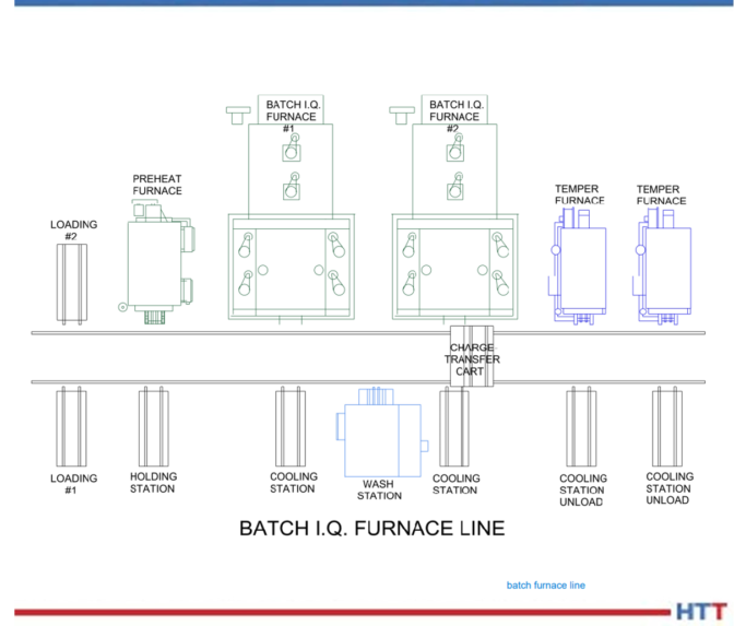
MICHAEL MOUILLESEAUX: You typically don’t have a singular furnace, you have a system. What’s involved in a system?
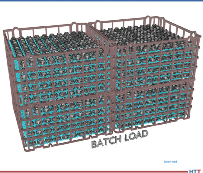
What we’re looking at here is a relatively simple system. You have a loading operation. Obviously, the parts need to be loaded in baskets or fixtures. In some way, the load needs to be built. Typically, there is a station for that.
Following loading, it’s put into a preheat furnace. A preheat furnace is identical to what we would call a “temper” or a “draw.” You can thermally clean the parts by heating them up to 800°F. The other thing is that those that you put into that part are 20% the cost of getting those BTUs when you’re putting it in the high heat furnace, so it just makes economic sense. You’re cleaning the parts and you’re preheating the parts.
Then you’re going to put it into the furnace to perform the furnace operation; it’s either going to be top cooled or quenched. If it’s top cooled, you’re going to stop that top cooling operation at 300°F or 400°F. You’re going to put it in a cooling station and allow it to cool to room temperature. If you quench the part, if you’re modified marquenching it, it’s 250°F plus; if it’s quenched in regular oil, it could be 150–180°F.
The next operation is to wash the part. Typically, you don’t want to wash hot parts; you want to allow them to cool to room temperature. Sometimes you do, but more often than not, no.
Then there’s the wash station; you’re washing the parts. Then, you’re taking them out of the washing station and allowing them to drip. Then, you’re going to put them into a temper and you’re going to temper it for three to seven or eight hours, or something of that nature. You extract the load from the tempering furnace, put it in a cooling station, and allow it to cool down to room temperature so you can then unload it.
As you can see, the way that is accomplished is with this transfer cart. The transfer cart extracts the load from the loading table, pushes it into the preheat furnace, pulls it out of the preheat furnace, and pushes it into the batch furnace. Then the batch furnace quenches it, but when the outer vestibule door is opened, the transfer car must go in and get the load and pull it back onto the transfer car. The car pushes it across the aisle into the cooling station, picks it up, puts it in the wash, takes it out of the wash, puts it into the temper, takes it across the aisle when the tempering is finished, extracts it from the temper, and puts in on the cooling station. That transfer cart is an important piece of equipment.
But you can see there are a lot of moving parts to this. And you might ask, “Why would you do this?” Well again, because of the flexibility of the batch furnace. In this example, batch furnace #1 can be performing neutral hardening; batch furnace #2, at the same time, can be carbonitriding; the neutral hardening load finishes and the next load that goes in there could be annealed; after the load is annealed, then you could take a load and it could be normalized; then you could go back and you could neutral harden again.
So, if you don’t have multiple loads of the same thing, this offers a degree of flexibility that almost is not available in any other type of atmosphere processing equipment.
DOUG GLENN: Right. And the fact that you have more than one furnace, more than one high heat furnace, more than one temper furnace, gives you almost (not exactly, but closer to) a continuous process even though each furnace is a “batch,” if you will.
MICHAEL MOUILLESEAUX: Correct.
There are charge cars that are automated, so the charge car knows where the loading station is — it goes to that loading station. You could either have a human unload it or, in the highest degree of automation, it gets there and you have a PLC that is overseeing or supervising this entire operation, and it would know to take that load onto the cart, where to take it next, and what to do. It becomes a semi-automated method of heat treating.
Properties of the Pusher Furnace (19:53)
DOUG GLENN: Let’s move on to the pusher furnace, the continuous system.
MICHAEL MOUILLESEAUX: The pusher furnace, as you can see in this description, contains the vestibule, the furnace, and the quench. We’ve just broken it down into the pusher furnace proper.
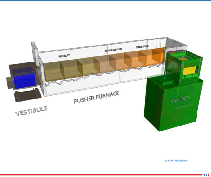
Loads are put into the vestibule and then, sequentially, they move their way through the furnace. The first zone of the furnace would be what we would call the “preheat” and that’s where we bring the part up to temperature.
In this example, we’re showing boost-diffuse. This is an example where we would be carburizing. The first couple of positions would be a boost. We carburize at a higher carbon content because it diffuses more rapidly at the initial point of carburizing. Then, at the tail end of the carburizing cycle, we reduce the carbon content to what our desired surface carbon content would be.
An example might be: We would start out and we’d boost at 1% or 1, and the diffuse cycle would be .8% carbon. You do that for a couple of reasons: You want to mitigate any retained austenite, so the bar is quenched at a higher carbon. You have opportunity for development of an unacceptable amount of retained austenite. At the extreme, you could start developing carbides and those become very difficult to re-solution. That’s the rationale for having a boost-diffuse. You do that same thing in a batch furnace; I just didn’t describe that as such.
And then the drop zone. We want to reduce the temperature prior to quenching so that we have very uniform quenching properties and if the components that we’re heat treating are distortion-critical, it’s very important as to what the temperature is prior to quenching.
So, we carburize at a high temperature (1700 Fahrenheit/1750 Fahrenheit), because the diffusion rate is much higher at that temperature. But we only want to quench these parts at 1500 or 1550 Fahrenheit because we want to have an absolute minimum amount of distortion.
Every hour, the vestibule door to the quench is going to open and you would cross-push that load into the quench vestibule, you would close the door, and just as the animation described in the batch furnace, that load would drop on an elevator into the quench.
Now that we’ve done that, we have an opening. That last position is open. So, we go to the vestibule on the front end of the furnace, we open that door, we put a load in there, we close the door, and we’ll close it long enough for us to reestablish the furnace pressure (no more than 3–5 minutes). Once we’ve established furnace pressure, we can open the door between the vestibule and the first preheat zone, and then to the left of the vestibule is going to be a mechanism for pushing these loads, hence the term “pusher”? Could it be hydraulic? It could. Could be mechanical? Both are employed.
What you’re doing is pushing it further by one position. Because the last position is open, the second to the last load progresses into the last position, the load that you put in the vestibule goes into the first position.
DOUG GLENN: A couple quick questions: Really, the sequence starts with the load being pushed out of the furnace into the quench vestibule and then dropped in. That leaves that last spot open in the furnace. Then everything else starts and we push it all down, correct?
MICHAEL MOUILLESEAUX: You are correct.
DOUG GLENN: In this illustration, it looks like there are divisions between each of these different locations. In the preheat, it looks like there are three or four; in the boost-diffuse, it looks like you’ve got two or three. Those aren’t actually physical barriers; You’re just showing where the load would progress to, correct?
MICHAEL MOUILLESEAUX: You are correct.
DOUG GLENN: Are there any chamber divisions in a pusher furnace?
MICHAEL MOUILLESEAUX: In a pusher furnace, you have arches above the load and that helps to compartmentalize. The key word there is “helps.” You don’t have an actual compartmentalization.
Let’s say that we want to perform a carburize at 1700°F in this furnace. If you had three preheats, you may want to perform these somewhere below the 1700°F with the last position being at 1700°F so that the load that goes into the carburizing zone is at temperature and it’s ready to accept carbon.
The carburizing zone would all be at the same temperature, but you have to understand these parts are all at 1700°F and we want to quench it at 1550°F, let’s say. We have two positions that we are going to allow the load to cool down to 1550°F.
So, would you want a zone arch there? I think that you would, yes. Would you want a fan in those zones? If you had a fan in those zones, and you are circulating the atmosphere through those loads, you have a better opportunity to attain a uniform temperature from the top to the bottom of the load than if you did not.
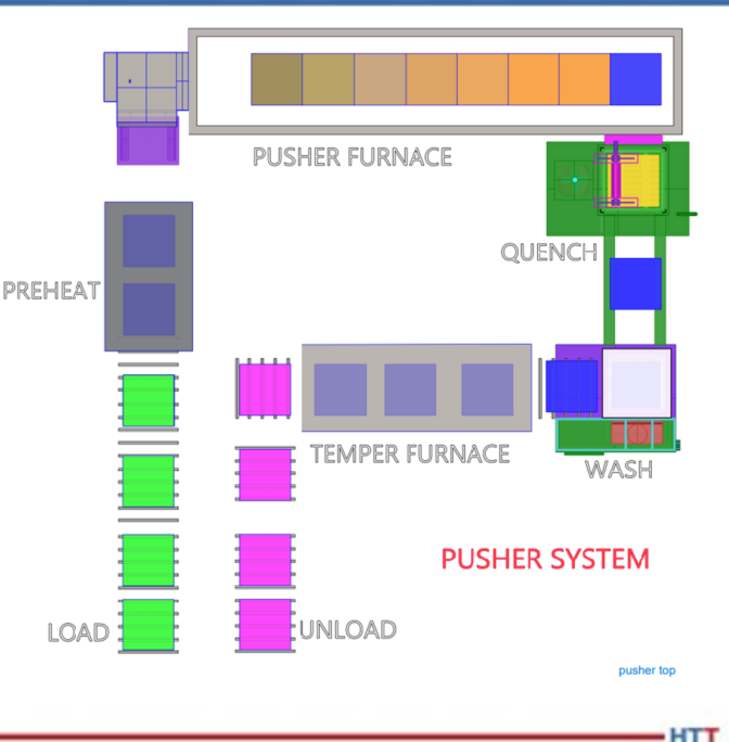
MICHAEL MOUILLESEAUX: Here’s a pusher furnace system. Typically, but not always, pushers are put into a system because you have multiple operations that you must perform. This example is in a U-shape. The loading and unloading are next to each other. This could be a linear layout.
In another life, I worked for a company in Syracuse, New York that had 14 furnaces that were all linearly oriented. So, the person on the front of the furnace did one thing, the person on the back of the furnace did another thing, and they really didn’t communicate.
I, personally, am not a fan of that. I like this operation because you can have one or two people performing the loading and unloading operation, and you could have a furnace operator who would be responsible for the overall control of this piece of equipment.
You can see that we have four loads here that are in whatever way we chose to fixture them — baskets, fixtures, or whatever it might be. We’ve put a couple of parts in a preheat so we could perform that same cleaning that we talked about in preheating the load with low-cost BTUs. The preheat then goes into the vestibule, the loads progress down through the furnace as we described, you get to the end and that load is quenched. When the load comes out of the quench, just as in the batch furnace, it’s going to be 150–200°F plus. We want that to cool down to room temperature because the next operation is going to be washing.
After the load to cools down to room temperature, we then put it in the wash. Following the wash operation, you might have a drip station. So, whatever it was that you have washed off in the water, you don’t want that to go into the temper. Following the drip station, then you would go into the tempering furnace. Here we’re showing three positions; it could be three, it could be six, it could be nine. This is just an example.
Following the tempering operation, we would go out and in that first position, you might have a blower underneath and you would be circulating, room temperature air through it up into a duct work ahead and that’s how you would cool the room down to low temperature. Those loads would progress down that unload station so, at the very end, you are unloading the parts, perhaps for a subsequent shop blast cleaning operation or development of rust preventative or maybe they’re just put back into the customer’s container.
In a captive operation, they might go into a container where the parts would go on to a subsequent grinding or hard-turning operation.
This can be automated. Here you can see that the loads progress into the preheat, they progress through the furnace, they go into the quench, and they’re put into the wash. It’s quick.

DOUG GLENN: Yes. It doesn’t happen this fast in real life, everyone!
MICHAEL MOUILLESEAUX: In the temper, the load exits the temper and goes into the unloading station. The point of this is to show that it progresses through the furnace.
The advantage is that you have relatively small loads that you’re processing, there is a very consistent process in the pusher furnace, and what you’re on for is that however you’ve designed this system, every load goes through every station. You don’t have an opportunity to easily extract a load as quenched and not wash it. It can be done. You could have a furnace designed to do that, but it’s not easy. After it’s washed, as you can see in this animation, typically it’s going to progress into the temper. Could you design a station that would allow you to offload it? You could, but normally that’s not how that’s done.
So, the load progresses through the temper and then you go in to where it is then subsequently unloaded.
If the batch furnace’s strong suit is the fact that it is extremely flexible — particularly in a “systemic” way — the pusher furnace’s strength is its productivity. °
DOUG GLENN: Yes, higher levels of productivity. But you’ve got to have, if not the same product, at least the same process on whatever it is you’re putting in there.
MICHAEL MOUILLESEAUX: Bingo. That’s exactly what you must have there, yes.
About the expert: Michael Mouilleseaux is general manager at Erie Steel LTD. Mike has been at Erie Steel in Toledo, OH since 2006 with previous metallurgical experience at New Process Gear in Syracuse, NY and as the Director of Technology in Marketing at FPM Heat Treating LLC in Elk Grove, IL. Having graduated from the University of Michigan with a degree in Metallurgical Engineering, Mike has proved his expertise in the field of heat treat, co-presenting at the 2019 Heat Treat show and currently serving on the Board of Trustees at the Metal Treating Institute.
Contact: mmouilleseaux@erie.com
To find other Heat Treat Radio episodes, go to www.heattreattoday.com/radio.