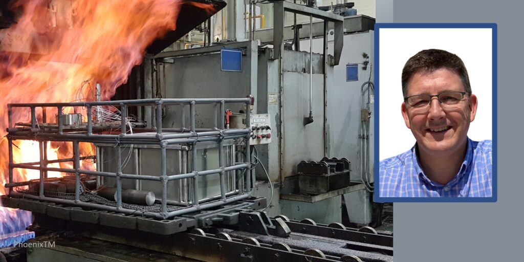
The future of heat treating requires new manufacturing solutions like robotics that can work with modular design. Yet so also does temperature monitoring need to be seamless to know how effectively your components are being heat treated — especially through being quenched.In this Technical Tuesday,learn more abouttemperature monitoring through the quench process.
Gas Carburization
Contact us with your Reader Feedback!
Carburizing has rapidly become one of the most critical heat treatment processes employed in the manufacture of automotive components. Also referred to as case hardening, it provides necessary surface resistance to wear, while maintaining toughness and core strength essential for hardworking automotive parts.
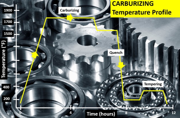
Figure 1. Typical carburizing heat treat temperature profile showing the critical temperature/time steps: (i) carburization, (ii) quench, and (iii) temper. (Source: PhoenixTM)
The carburizing process is achieved by heat treating the product in a carbon rich environment (Figure 1), typically at a temperature of 1562°F–1922°F (850°C–1050°C). The temperature and process time significantly influence the depth of carbon diffusion and other related surface characteristics. Critical to the process is a rapid quenching of the product following the diffusion in which the temperature is rapidly decreased to generate the microstructure, giving the enhanced surface hardness while maintaining a soft and tough product core.
The outer surface becomes hard via the transformation from austenite to martensite while the core remains soft and tough as a ferritic and/or pearlitic microstructure. Normally, carburized microstructures following quench are further tempered at temperatures of about 356°F (180°C) to transform some of the brittle martensite into tempered martensite to enhance ductility and grindability.
Critical Process Temperature Control
As discussed, the success of carburization is dependent on accurate, repeatable control of the product temperature and time at that temperature through the complete heat treatment process. Important to the whole operation is the quench, in which the rate of cooling (product temperature change) is critical to achieve the desired changes in microstructure, creating the surface hardness. It is interesting that the success of the whole heat treat process can rest on a process step which is so short (minutes), in terms of the complete heat teat process (hours). Getting the quench correct is not only essential to achieve the desired metal microstructure, but also to ensure that the physical dimensions and shape of the product are maintained (no distortion/warping) and issues such as quench cracking are eliminated.
Obviously, as the quench is so critical to the whole heat treat process, the correct quench selection needs to be made to achieve the optimum properties with acceptable levels of dimensional change. Many different quenchants can be applied with differing quenching performances. The rate of heat transfer (quench rate) of quench media in general follows this order from slowest to quickest: air, salt, polymer, oil, caustic, and water.
Technology Challenges for Temperature Monitoring
When considering carburization from an industry standpoint, furnace heat treat technology generally falls into one of two camps, embracing either air quench (low pressure carburization) or oil quench (sealed gas carburization/LPC with integral or vacuum oil quench). Although each achieves the same end goal, the heat treat mechanisms and technologies employed are very different, as are the temperature monitoring challenges.
To achieve the desired carburized product, it is necessary to control and hence monitor the product temperature through the three phases of the heat treat process. Conventionally, product temperature monitoring would be attempted using the traditional trailing thermocouple method. For many modern heat treat processes including carburization, the trailing thermocouple method is difficult and often practically impossible.1 The movement of the product or product basket from stage to stage, often from one independent sealed chamber to another (lateral or vertical movement), makes the monitoring of the complete process a significant challenge.
With the industry driving toward fully automated manufacturing, furnace manufacturers are now offering the complete package with full robotic product loading that includes shuttle transfer systems and modular heat treat phases to process both complete product baskets and single piece operations. Although trailing thermocouples may allow individual stages in the process to be measured, they cannot provide monitoring of the complete heat treat journey. Testing is therefore not under true normal production conditions, and therefore is not an accurate record of what happens in normal day to day operation.
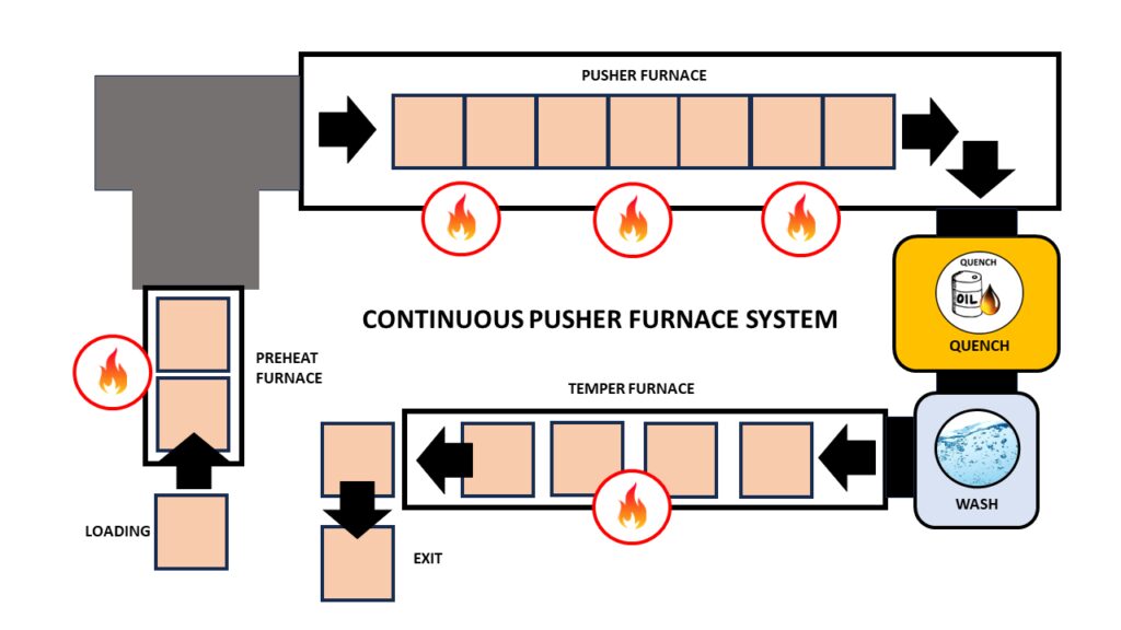
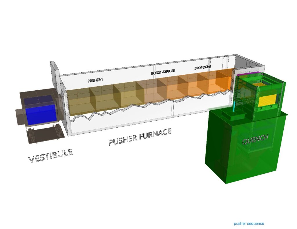
Figure 2 shows schematic diagrams of two typical carburizing furnace configurations that would not be possible to monitor using trailing thermocouples. The first shows a modular batch furnace system where the product basket is transferred between each static heat treat operation (preheat, carburizing furnace, cooling station, quench, quench wash, temper furnace) via a charge transfer cart. The second shows the same heat treat operation but performed in a continuous indexed pusher furnace configuration where the product basket moves sequentially through each heat treat operation in a semi-continuous flow.
Thru-process temperature monitoring as a technique overcomes such technical restrictions. The data logger is protected by a specially designed thermal barrier, therefore, can travel with the product through each stage of the process measuring the product/process temperature with short, localized thermocouples that will not hinder travel. The careful design and construction of the monitoring system is important to address the specific challenges that different heat treat technology brings including modular batch and continuous pusher furnace designs (Figure 2).2
The following section will focus specifically on monitoring challenges of the sealed gas carburizing process with integral oil quench. Technical challenges of the alternative low pressure carburizing technology with high pressure gas quench have previously been discussed in an earlier publication.3
Monitoring Challenges of Sealed Gas Carburization — Oil Quench
Figure 3. “Thru-process” temperature monitoring system for use in a sealed carburizing furnace with integral oil quench — (3.1) Monitoring system entering furnace with thermocouple fixed to automotive gears, product test pieces (3.2) System exiting oil quench tank (3.3) System inserted into wash tank with product basket (Source: PhoenixTM)
Presently, the most common traditional method of gas carburizing for automotive steels is often referred to as sealed gas carburizing. In this method, the parts are surrounded by an endothermic gas atmosphere. Carbon is generated by the Boudouard reaction during the carburization process, typically at 1562°F–1832°F (850°C –1000°C). Despite the dramatic appearance of a sealed gas carburizing furnace, with its characteristic belching flames (Figure 3), from a monitoring perspective, the most challenging aspect of the process is not the heating, but the oil quench cooling. For such furnace technology, the historic limitation of “thru-process” temperature profiling has been the need to bypass the oil quench and wash stations, missing a critical process step from the monitoring operation. Obviously, passing a conventional hot barrier through an oil quench creates potential risk of both system damage from oil ingress and barrier distortion, as well as general process safety. However, the need to bypass the quench in certain furnace configurations by removing the hot system from the confined furnace space could create significant operational challenges, from an access and safety perspective.
Monitoring of the quench is important as ageing of the oil results in decomposition (thermal cracking), oxidation, and contamination (e.g. water) of the oil, all of which degrade the viscosity, heat transfer characteristics, and quench efficiency. Control of physical oil temperature and agitation rates is also key to oil quench performance. Quench monitoring allows economic oil replacement schedules to be set, without risk to process performance and product quality.
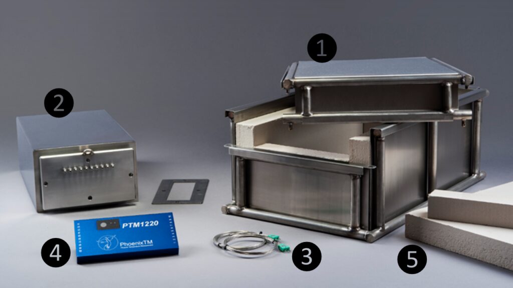
Figure 4. “Thru-process” temperature monitoring system oil quench compatible thermal barrier design: (1) Robust outer structural frame keeping insulation and inner barrier secure; (2) Internal thermal barrier — completely sealed with integral microporous insulation protecting data logger; (3) Mineral insulated thermocouples sealed in internal thermal barrier with oil tight compression fitting; (4) Multi-channel high temperature data logger; and (5) Sacrificial insulation blocks replaced after each run.
(Source: PhoenixTM)
To address the process challenges, a unique thermal barrier design has been developed that both protects the data logger in the furnace (typically three hours at 1697°F/925°C) and also protects during transfer through the oil quench (typically 15 mins) and final wash station (Figure 3). The key to the barrier design is the encasement of a sealed inner barrier with its own thermal protection with blocks of high-grade sacrificial insulation contained in a robust outer structural frame (Figure 4).
Quench Cooling Phases
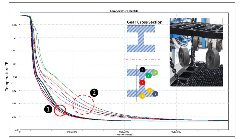
Monitoring the oil quench in carburization gives the operator a unique insight into the product’s specific cooling characteristics, which can be critical to allow optimal product loading and process understanding and optimization. From a scientific perspective, the quench temperature profile trace, although only a couple of minutes in duration, is complex and unique. From a zoomed in quench trace (Figure 5) taken from a complete carburizing profile run, the three unique heat transfer phases making up the oil quench cool curve can be clearly identified:
Figure 5. Oil quench temperature profile for different locations on an automotive gear test piece shows the three distinct heat transfer phases: (1) film boiling “vapor blanket”, (2) nucleate boiling, and (3) convective heat transfer. (Source: PhoenixTM)
Film boiling “vapor Blanket”: The oil quenchant creates a layer of vapor (Leidenfrost phenomenon) covering the metal surface. Cooling in this stage is a function of conduction through the vapor envelope. Slow cool rate since the vapor blanket acts as an insulator.
Nucleate boiling: As the part cools, the vapor blanket collapses and nucleate boiling results. Heat transfer is fastest during this phase, typically two orders of magnitude higher than in film boiling.
Convective heat transfer: When the part temperature drops below the oil boiling point. the cooling rate slows significantly. The cooling rate is exponentially dependent on the oil’s viscosity.
From a heat treat perspective, the quench step relative to the whole process (hours) is quick (seconds), but it is probably the most critical to the performance of the metallurgical phase transitions and achieving the desired core microstructure of the product without risk of distortion. By being able to monitor the quench step, the process can be validated for different products with differing size, form, and thermal mass. As shown in Figure 6, the quench curve profile over the three heat transfer phases is very different for two different automotive gear sizes.
Figure 6. Oil quench temperature profile for different automotive gear sizes (20MnCr5 case hardening steel) with different thermal masses: Passenger Car Gear (2.2 lbs) and Commercial Vehicle Gear (17.6 lbs) (Source: PhoenixTM)
Summary
As discussed in this article, one of the key process performance factors associated with gas carburization is the control and monitoring of the product quench step. Employing an oil quench, the measurement of such operation is now very feasible as part of heat treat monitoring. Innovations in thru-process temperature profiling technology offer specific system designs to meet the respective application challenges.
References
[1] Dr. Steve Offley, “The light at the end of the tunnel – Monitoring Mesh Belt Furnaces,” Heat Treat Today, February 2022, https://www.heattreattoday.com/processes/brazing/brazing-technical-content/the-light-at-the-end-of-the-tunnel-monitoring-mesh-belt-furnaces/.
[2] Michael Mouilleseaux, “Heat Treat Radio #102: Lunch & Learn, Batch IQ Vs. Continuous Pusher, Part 1,” interviewed by Doug Glenn, Heat Treat Radio, October 26, 2023, audio, https://www.heattreattoday.com/media-category/heat-treat-radio/heat-treat-radio-102-102-lunch-learn-batch-iq-vs-continuous-pusher-part-1/.
[3] Dr. Steve Offley, “Discover the DNA of Automotive Heat Treat: Thru-process Temperature Monitoring,” Heat Treat Today, August 2023, https://www.heattreattoday.com/discover-the-dna-of-automotive-heat-treat-thru-process-temperature-monitoring/.
About the Author
Dr Steve Offley (“Dr O”), Product Marketing Manager, PhoenixTM
Dr. Steve Offley, “Dr. O,” has been the product marketing manager at PhoenixTM for the last five years after a career of over 25 years in temperature monitoring focusing on the heat treatment, paint, and general manufacturing industries. A key aspect of his role is the product management of the innovative PhoenixTM range of thru-process temperature and optical profiling and TUS monitoring system solutions.
Needing to learn more about the fundamentals and latest developments of stop off coatings? Mark Ratliff, president of AVION Manufacturing Company, Inc., applies his background in chemical engineering to understand and create what makes the best stop-off coatings/paints for carburizing and other heat treat processes. In this episode, Mark and Heat Treat Radio host, Doug Glenn, uncover the varieties of coatings, their uses, and the future of coating solutions.
Below, you can watch the video, listen to the podcast by clicking on the audio play button, or read an edited transcript.
The following transcript has been edited for your reading enjoyment.
Chemistry in Coatings: Mark Ratliff’s Start in the Industry (00:22)
Contact us with your Reader Feedback!
Doug Glenn: I have the really great honor today of talking with Mark Ratliff from AVION Manufacturing. We’re going to do a “painting class” . . . kind of, but not really. Industrial paint — we’re going to talk about stop-off paints and things of that sort.
Mark has been working at AVION, currently located in Medina, Ohio, since 1994. He graduated with a Bachelor of Science degree in chemical engineering from the University of Cincinnati. Prior to that — I did not know this about you, Mark — he worked at Shore Metal Treating with your father, huh?
Mark Ratliff: That’s correct, yes.
Doug Glenn: How long was he there?
Mark Ratliff: Well, he started the company. I went working there and was loading baskets of parts since I was about 8 years old. He would pay me $5.00 for a basket, “under the table,” and that was a lot of money back then. I was really rich, at the time!
Mark Ratliff, President, Avion Manufacturing (Source: AVION Manufacturing)
Doug Glenn: That’s pretty cool. It is very interesting to see people’s backgrounds and how they got involved in the industry. A lot of people start young, you know? You may win the record though — 8 years old! The labor board may be calling about your childhood.
Why Use Stop-Off Paints? (01:54)
Let’s talk today. Technically, we want to talk about something that not everybody may know about, and I think you and your company are kind of experts on these things, and that’s stop-off paints. Just from a 30,000-foot view — and you don’t have to go into a lot of detail here, Mark — what are stop-off paints and why do we use them?
Mark Ratliff: Stop-off paints are protective barrier-type coatings. What they do is prevent either carburization or the nitriding process from entering into the steel. They were created probably well over 50 years ago as a replacement for copperplating these parts. In the past, a long time ago, they would copperplate the part that they did not want carburized or nitrided. That’s a time-consuming process as well as being very expensive. The stop-off coatings were developed as an economical alternative to copperplating.
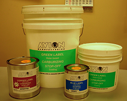
AVION Line of Stop-Offs (Source: AVION Manufacturing)
DougGlenn: When you say “copperplating,” does that mean it was actual thin sheets of copper metal?
MarkRatliff: That’s correct, yes.
Doug Glenn: And you actually had to wrap whatever you did not want nitrided or carburized in this copper and that would keep it from nitriding?
Mark Ratliff: That’s correct, yes.
Doug Glenn: Just in case people don’t know — but I would imagine that most people that are listening to this do know — nitriding and carburizing are both surface hardening technologies in which either nitrogen (in the case of nitriding) or carbon (in the case of carburizing) are infused into the surface. That, of course, gives improved wear properties, typically corrosion properties to those areas that receive the infusion of the metal.
Why do people not want the nitrogen or carbon to be infused to certain areas of the part?
MarkRatliff: When you harden a part, as with carburization or nitriding, a lot of times hardness equates to brittleness. So you may induce certain stress in various parts, in various areas.
Also, if you want to do a post-heat treatment machining on the part, it would be virtually impossible if that part were carburized or nitrided because the surface is so hard that the tool can’t cut through it to do further machining on the part.
“If you want to do a post-heat treatment machining on the part, it would
be virtually impossible if that part were carburized or nitrided because the surface is so hard that the tool can’t cut through it to do further machining on the part.”
— Mark Ratliff, AVION Manufacturing
Doug Glenn: Gotcha.
Can you give a couple examples of parts, and if you can do a description of where on those parts you might apply a stop-off coating?
Mark Ratliff: Well, a lot of times the end user (the customer) is painting an end of a shaft where he’ll heat treat the shaft and make the shaft harder, but he wants to spin a thread on the end of that shaft. That’s a prime example of why you would use a stop-off coating.
A lot of times, the parts are made with the threads already on, but you don’t want those threads to be hardened because, again, hardness equals brittleness, and those threads would crack off after heat treatment. That would be an area where you would apply a stop-off coating.
Doug Glenn: Tell us a little bit about the actual physical “properties" of these stop-off coatings. We also call them “stop-off paints.” I’m assuming a lot of times these are just painted on — it’s a liquid format.
Mark Ratliff: They are all supplied in liquid form with the viscosity ranging right around 3500–8500 centipoise (cP). For the carburizing stop-off, we have two different kinds. (This is not new in the industry; most people know the formulations of the stop-offs.)
We have boric acid-based stop-offs; we have two different kinds of that — a waterborne and a solvent borne. The idea behind the boric acid-based stop-offs is that as the boric acid thermally decomposes, it creates a boron oxide glass. This glass is actually the diffusion barrier of the carbon. What’s nice about the boric acid-based stop-offs is that they’re water washable after the heat treatment process; the coating and the residue can get washed off.
Another type of stop-off coating that we have is based on silicate chemistry. A silicate chemistry is basically like putting a glass on the part. It’s more of a ceramic-based coating. It works very, very well, but the drawback of the silicate-based stop-offs is that you have to bead-blast the parts after heat treatment; it does not wash off in water.
Doug Glenn and Mark Ratliff
Doug Glenn: So, you’ve got to brush it off.
Mark Ratliff: You’ve got to brush it off, mechanically, correct.
Doug Glenn: That’s interesting.
When I think of painting something on and then putting it into a furnace, the first thing I think of is that paint is going to get completely obliterated in the furnace. But you just kind of answered that question. Those things will either transform into a glass or a ceramic of some sort after they’ve been in high heat for a while, and that’s what creates the barrier.
Mark Ratliff: That’s correct.
You have the active ingredient in the stop-offs — you either have the silicate or you have the boric acid. Those are the active ingredients. The vehicle that the paint itself — be it the water-based latex or the solvent-borne bead — those do, indeed, get charred off. They get burned off, leaving the active ingredient behind.
Doug Glenn: Are you able to use either of those — the water-based or the solvent-based — in vacuum furnaces? Do you have any trouble with off-gassing and things of that sort?
Mark Ratliff: Yes, a little bit. We’ve got to be careful in the vacuum furnace market because you do have the off-gassing. The combination of the vacuum and the heat at once can cause the coating to boil and blister. We do recommend pre-heat treatments when doing a vacuum operation.
Doug Glenn: And the pre-heat just kind of helps it adhere to the part without the blistering, I guess?
Mark Ratliff: That’s correct. And it drives off a lot of the residual water or solvent that might be left in the coating.
Different Chemistry, Different Technology: Plasma Nitriding Stop-Off Coatings (08:32)
Doug Glenn: Okay, good.
Now I understand that there is a new product coming out on the nitriding end of things. Can you tell us a little bit about that and why you’re developing it?
Mark Ratliff: We’ve been making a nitriding stop-off coating since 1989 when we came out with our water-based version. We actually had it patented. We were the first on the market with a water-based nitriding stop-off. This particular stop-off has been used in the industry for 45 years now.
We got called by a current customer asking, “Hey, do you have a plasma or an ion-nitriding stop-off?” At the time, we did not. So, we developed a new plasma — aka, ion-nitriding — stop-off, and that’s a different chemistry, different technology. It is going to be available in the market very soon.
Doug Glenn: Interesting.
I’m curious about this: Are stop-off paints used more in carburizing or nitriding?
Mark Ratliff: By far, carburizing — it’s probably 10 to 1 carburizing to nitriding, for sure.
Doug Glenn: Okay, gotcha.
This episode of Heat TreatRadio is sponsored by AVION.
So, you’ve been doing this for 30 or some years, right?
Mark Ratliff: It will be my 30th anniversary in the month of April.
Doug Glenn: Very nice! Well, congratulations.
Mark Ratliff: I did work for my father prior to that, when he ran AVION for many years before that.
Doug Glenn: Well, congratulations, first off — that’s good. It shows longevity, which is good.
Memorable Moment of Innovation (11:11)
Doug Glenn: Has there been a memorable challenge that you had to deal with, with these stop-off paints?
Mark Ratliff: One thing I’m particularly proud of, Doug, is we always had the water-based carburizing stop-off coating — both varieties — the boric acid-based and the silicate-based. I had a few customers reach out to me and say, “Hey, we’re doing heat treatment for the aerospace industry or for the automotive industry, and they don’t like water-based coatings on their parts,” because you run into corrosion, you run into rust, and so forth and so on. So, these customers asked me to create the solvent-borne, which we did about seven or eight years ago.
One thing I’m particularly proud of is, I got called by the Fiat Chrysler plant in Michigan (they’re going by Stellantis, now), and unbeknownst to them, their current stop-off provider, at the time, changed the formulation. (That was due to the REACH regulations in Europe.) Since they changed the formulation, Stellantis started seeing all these problems. So, they reached out to me and asked, “Do you have an equivalent? We’d like a solvent-borne stop-off.” I was quick to respond, “Oh, by the way, yes, we do. And yes, our product is better,” because even though it’s solvent-borne, we created a nonflammable stop-off coating. In addition to being nonflammable, the solvent that we used in the coating is VOC exempt — VOC meaning volatile organic compounds — which are basically air pollutants that people want to avoid when using these stop-off coatings.
AVION Green Label pail (Source: AVION Manufacturing)
Doug Glenn: Okay, very interesting. I was going to ask you — because I saw on your website — about your green label, which you kind of hit on with the VOC part, but can you tell us a little bit about the green label products that you have and why you’re calling them “green label”?
Mark Ratliff: We called it “green label” a long time ago — that was our original stop-off which kicked off our business 50+ years ago. But I think you’re referring to our eco green label which we created about two years ago.
We’ve been getting a lot of pressure to remove VOCs from our coatings. Clients like John Deere and Caterpillar said, “Hey, we love your coating, but if you could do anything to get the VOCs out of it, we’d really appreciate it.” So, that was one of the biggest goals and one of the biggest accomplishments — to create a coating that didn’t have any of these VOC or HAP (hazardous air pollutants)-type solvents in the coating, and we have successfully done that.
Doug Glenn: That’s good. Especially in the ‘green movement’ that’s going on today, that’s obviously very important.
What coating solution should heat treaters be looking at, in the near future? Is it just VOC stuff, the lack of VOC, or what?
Mark Ratliff: Well, yes, of course. I mean, we’re proud to say that all of our coatings are virtually VOC-free. We are still making the original green label because some customers are not happy to change, so we still offer that. But every single one of our coatings right now have a less than 10 gram/liter VOC threshold, and we’re really quite proud of that.
But, you know, as you’re talking about new coatings coming to the market, we’re coming out with the plasma nitriding stop-off. But we’re also looking into a stop-off for salt bath carburizing. We’ve had a couple people reach out to us, just recently, asking, “Do you have a coating that we can use to paint on the parts that go into a salt bath carburizing operation?”
Doug Glenn: That would be interesting because there is a bit of abrasion going on there, yes?
Mark Ratliff: There is, correct.
Final Questions: Supply Chain, Technical Assistance, and Target Markets (14:51)
Doug Glenn: Now, that’s interesting.
I have two additional questions for you. One has to deal with supply chain issues. Have you guys had any issues with being able to deliver quickly or anything of that sort, ala Covid?
Mark Ratliff: Sure. Right after Covid, we had trouble getting the main ingredient for the carburizing stop-off coating which is boric acid. Currently, I have three suppliers that supply that to me, and there was a point in time where none of them could get the material because the manufacturer of this product was not delivering east of the Mississippi. So, I had to do several days of researching and scrounging around, and I found a distributor in California that said, “Yes, we can get it to you, but you have to buy a whole truckload, which we were very happy to do.”
Doug Glenn: Yes, you take what you can get, at that point.
But no issues now?
Mark Ratliff: No, everything is pretty much back to normal. I mean, gone are the days where you could pick up the phone and get material delivered to you in three days, but most of our raw materials get delivered in under two weeks, and we keep a pretty adequate inventory of all of our raw materials so that we don’t run out of anything.
Doug Glenn: So, you get the raw materials. Do you do your own formulations there? I mean, do you actually do the mixing and all that stuff?
Mark Ratliff: We do. Everything is all done here, in-house, correct.
Doug Glenn: Finally, technical assistance and competency on your guys’ part: Do you have people on your staff — yourself or others — that if a customer calls in with an issue, you can help talk them through it?
“[Look] at the copperplating method: It’s, number one, very expensive, and number two, from what I’ve been told, it’s not very environmentally friendly — you’re working with a lot of hazardous ingredients, hazardous waste."
— Mark Ratliff, AVION Manufacturing
Mark Ratliff: Absolutely. So, I’m the “go to guy” here at AVION. If anyone has any technical questions, I’m the one that’s going to be answering them. And if it’s something where I need to come out to the plant, I’ll get in my car or get on a plane and visit that customer, if the quantity of it dictates that.
Doug Glenn: Yes, sure; it’s got to be a good business opportunity, obviously. But I’m sure you can use the phone to answer questions too.
Mark Ratliff: Yes, most of the time it’s by phone.
Doug Glenn: So, Mark, in the marketplace, is there an ideal client, someone who maybe should be considering stop-off paints that isn’t currently using it? Is there someone out there that you would say, “Hey, you know, if you’re doing this, maybe you ought to think about stop-off paints, if you’re not already doing them.”
Mark Ratliff: Well, I would certainly still target those that are copperplating. Look at the copperplating method: It’s, number one, very expensive, and number two, from what I’ve been told, it’s not very environmentally friendly — you’re working with a lot of hazardous ingredients, hazardous waste. So, those are the types of people that I will continue to target for stop-off coatings.
Doug Glenn: Well, Mark, listen, that’s great. Hopefully, this has been a good primer for people who didn’t know what stop-off paints/coatings were, and hopefully they can get ahold of you if they need something. I appreciate you being with us.
Mark Ratliff: Okay, thank you very much, Doug. I appreciate it myself.
About the Expert
Mark Ratliff started at Avion Manufacturing in 1994 after earning his bachelor’s of science degree in Chemical Engineering at the University of Cincinnati. Prior to getting his degree, Mark spent many of his summer breaks working for his father at Shore Metal Treating where he gained a good deal of knowledge about the heat treating industry.
Have you decided to purchase batch or continuous furnace system equipment? Today's episode is part 2 of the Heat Treat Radio lunch & learn episode begun with Michael Mouilleseaux of Erie Steel. Preceding this episode were Part 1 (episode #102) and a Technical Tuesdaypiece, so listen to the history of these systems, equipment and processing differences, and maintenance concerns before jumping into this episode about capability and throughput.
Doug Glenn,Heat Treat Todaypublisher and Heat Treat Radio host; Karen Gantzer, associate publisher/editor-in-chief; and Bethany Leone, managing editor, join this Heat Treat Today lunch & learn.
Below, you can watch the video, listen to the podcast by clicking on the audio play button, or read an edited transcript.
The following transcript has been edited for your reading enjoyment.
An Example: Carburizing (00:52)
Michael Mouilleseaux: What we want to do here is just compare the same part, the same heat treating process, processed in a batch furnace and processed in a pusher.
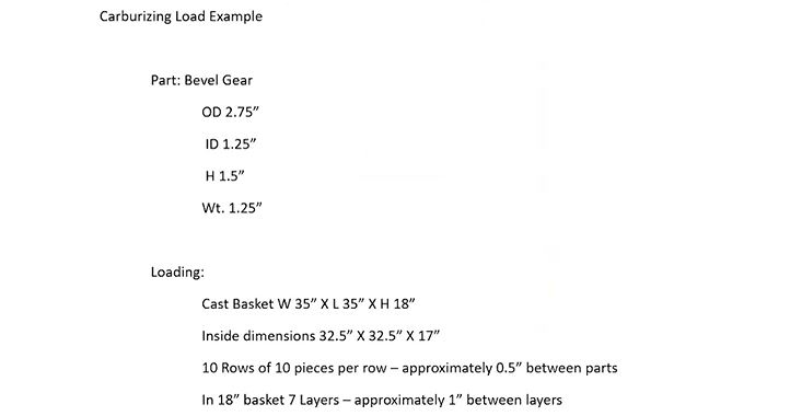
Figure 1: Carburizing Load Example (Source: Erie Steel)
Here we’re just going to make an example:
Pusher Load Description (00:58)
Contact us with
your Reader Feedback!
I’m going to take a fictious gear: it’s 2 ¾ inch in diameter, it’s got an inside diameter of an inch and a quarter, it’s an inch and a half tall, and it weighs 1.25 pounds. For our purposes here, we’re going to put these in a cast basket. For the furnace that we’re going to put them in, the basket size is 36 inches square — so, it’s 36 x 36. The height in this pusher furnace is going to be 24 inches; the inside dimensions of a 36-inch basket (actually it’s a 35-inch basket that sits on a 36-inch tray) is 32 ½ inches.
Michael Mouilleseaux General Manager at Erie Steel, Ltd. Sourced from the author
We’re going to say that this basket is 18 inches tall, so we’re going to get 7 layers of parts so that there’s approximately 1 inch between each layer of parts. This loading scheme gets us 700 pieces in a basket; it gets us 875 pounds net.
So the 36-inch basket that’s 18 inches tall and we’ve got 10 rows of 10 pieces, and we’ve got 7 layers of these things, so we have some room in between them. The reason for that is circulation of atmosphere and quenchant. This is what’s going to constitute the pusher load.
Batch Load Description (03:09)
Now, when we go to the batch load, we’re going to take four of these, because the batch furnace that we’re going to compare this to is going to be 36 inches wide and it’s going to be 72 inches long. We have two baskets on the bottom, 36, and then two of them is 72, and two on top. They’re 18 inches high, so 18 and 18 is 36 — a standard 36 x 72. It’s got 40 inches of height on it. I can take that 36 inches, put it on a 2 ½-inch tray and I can get it in and out of the furnace.
What is this four baskets? 2800 pieces in a load and 3500 pounds. That’s the difference. I’m comparing one basket, 700 pieces and 875 pounds and we’re going to compare that to what we would do if we ran a batch load, which is significantly more. It’s 2800 pieces and 3500 pounds.
What do we want to do with this?
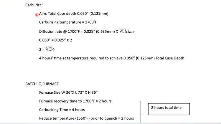
Let’s say that we’re going to carburize this, and we want 50 thousandths case (total case depth of 0/050”). Now, I will show you very soon why we’ve chosen 50 thousandths case. Because at 1700°F (which is what we’re going to carburize at), the diffusion rate is 25 thousandths of an inch times the square root of time.
Now, I can do that math in my head. 25 thousandths times 2 is 50 thousandths. That means we need four hours. So, the part would have to be in the furnace for four hours, at temperature, carburizing, in order to achieve 50 thousandths case.
Figure 2: Batch IQ Carburizing Load (Source: Erie Steel)
Batch Furnace Time (04:59)
Let’s look at the next section. As we said, the furnace is 36 x 72 x 36 and we have 2800 pieces in the load. So, that is 1700°F. We’re going to say that there is 3500 pounds and there is probably another 800 or 900 pounds in fixturing so that’s about 4500 pounds. It’s very conservative; in a 36 x 72 furnace, you could probably get away with running 6,000 pounds. This is just a load that is well within the capability of that.
Furnace recovery is going to take two hours.
Doug Glenn: Meaning, it’s going to take you two hours to get up to temperature.
Mike Mouilleseaux: Until the entirety of the load is at 1700°F, that’s right. Inside, outside, top to bottom.
We’re going to carburize this at four hours, as we described previously; we calculated that and we need four hours to get our 50 thousandths case. Then we’re going to reduce the temperature in the furnace to 1550°F so that we can quench it.
So, we have two hours of furnace recovery, four hours at carburizing, two hours to reduce the temperature and attain a uniform 1550°F. That’s eight hours, and that’s what you would term an 8-hour furnace cycle.
We know that we have 2800 pieces in the load. In eight hours (2800 divided by 8) you’ve got 350 pieces/hour. That’s what the hourly productivity would be in this load.
We won’t talk about “what could we do.” There’s a lot of things that we could do. This is simply an example.
Pusher Furnace Time (07:05)
Now, in the pusher load, as previously described, it’s 36 x 36 and it’s 24 inches high. Now, we know that we have a basket that’s 18 inches high. Again, it’s going to sit on a 2-inch tray, so we’ve got 21 inches of the top of the basket that is going to fit in the furnace; there are going to be no issues with that whatsoever.
The controlling factor is that we want four hours at temperature. In the boost and diffuse, we have four positions. The furnace cycles once per hour.
We get one load size (700 pieces, 875 pounds) every hour. So, in this example (an 8-position, 36-square pusher) this process would yield 700 pieces an hour, and a batch furnace loaded as we described (same exact loading and number of pieces/basket) would yield 350 pieces/hour. In this scenario, the pusher furnace is going to produce twice the number of parts/hour that the batch would.
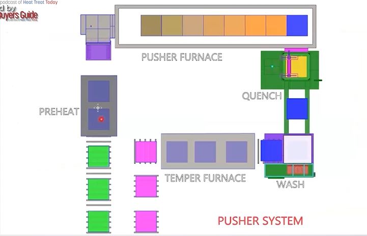
So, you would say, “Well, let’s just do that.” What you have to understand is that every hour, you are going to produce 700 pieces. If we went back and we looked at that description of what that pusher system looked like, you would see there are 23 positions in that. When I load a load, it’s going to be 23 hours before the first load comes out.
What we’re talking about is whether or not there were 700 pieces and 800 pounds, 23 of those[ET10][BL11] load.
The point would be, you either have to have enough of the same product or enough of similar product that can be processed to the same process to justify using something like this. Because if we want to change the cycle in the furnace. So, can we do that? The answer is absolutely, yes.
The preheat there, that stays at relatively the same temperature. The first zone in the furnace where we’re preheating the load, that temperature can be changed, as can the temperature in the boost diffuse and/or cycle time.
Figure 3: Pusher Furnace System (Source: Erie Steel)
So, in our example, we used an hour. What if you wanted 40 thousandths case and you’re going to be closer to 45 minutes or 50 minutes of time, how would you accomplish that? That can be done.
Typically, commercial heat treaters would come up with a strategy on how to cycle parts in and hold the furnace, or how many empties you would put in the furnace before you would change the furnace cycle.
Obviously, in the last two positions, where you’re reducing temperature, you could change the temperature in either the first two positions, where you’re preheating the load, or you could change the carburizing temperature, because when we’re dropping the temperature, it doesn’t have a material effect upon that.
Typically, in an in-house operation, you would not do that kind of thing, for a couple of reasons, not the least of which would be considering the type of people that you have operating these furnaces. They come in and out from other departments, and this is the kind of thing that you would want someone experientially understanding the instructions that you’ve given them. The furnace operator is not necessarily going to be the one to do it; this may be a pre-established methodology. You want them to execute that. But if you have somebody that is running a grinder and then they’re running a plating line and then they’re coming and working in the heat treat, that would not be the recipe for trying to make these kinds of changes.
As I described to you before, I worked in another life where we had 15 pushers. They were multiple-row pushers. We made 10,000 transfer cases a day. The furnace cycle on every furnace was established on the 1st of January, and on the 31st of December it was still running the same furnace cycle. You never changed what you were doing. The same parts went into the same furnaces and that’s how they were able to achieve the uniform results they were looking for.
Pusher Furnaces and Flexibility (12:45)
So, the longer the pusher furnace is, the less flexible it is.
In this example, you have eight. You know, there are pusher furnaces that have four positions. If you think about it, in a 4-position furnace, you could empty it out pretty quickly and change the cycle.
There are a lot of 6-position pusher furnaces in the commercial heat treating industry; that seems to be a good balance. The number of multiple-row pushers in the commercial industry, they’re fewer and far between. I’m not going to say they’re nonexistent, but enough of the same kind of product to justify that is difficult.
I think the bottom line here is, for companies that are having high variability, low quantity, low volume loads, generally speaking, your batch is going to be good because it’s very flexible, you can change quickly.
However, with a company like the one you were describing where there is low variability and very high volume, pushers are obviously going to make sense. But there is a whole spectrum in between there where you’re going to have to figure out which one makes more sense — whether you’re going to go with a batch or a continuous.
Mike Mouilleseaux: Possibly underappreciated is the aspect of distortion.
In that carburizing example, you’d say, “We have an alloy steel, we’re aiming for 50 thousandths case — what’s the variation within a load?” And I’m going to say that it is going to be less than 5 thousandths, less than 10%. From the top to the bottom, the inside to the outside, it’s going to be less than 5 thousandths. That same process, in the pusher furnace is going to be less than 3 thousandths.
That’s one aspect of the metallurgy. The other aspect is quenching.
Doug Glenn: 5 thousandths versus 3 thousandths — 3 thousandths is much more uniform, right?
Mike Mouilleseaux: Correct.
Doug Glenn: And that’s good because that way the entire load is more consistent (in the continuous unit, let’s say).
Mike Mouilleseaux: That is correct.
Then there is the consistency in quenching. In the batch furnace, you’re quenching 36 inches of the parts. If we had seven layers in the pusher, we have 14 layers of parts in the batch. What are the dynamics involved in that?
We have experience that the ID of a gear (it’s a splined gear) in a batch furnace, we were able to maintain less than 50 microns of distortion. There is a lot involved in that, that’s not for free; there’s a fair amount involved in that and it’s a sophisticated cycle, if you will. That same cycle in a pusher furnace, same case depth, similar quenching strategy, will give you less than half that amount of distortion.
To the heat treater, where we’re talking about the metallurgy of this, you’re going to think 5 thousandths or 3 thousandths is not a big deal.
To the end-user, that reduction in distortion all of a sudden starts paying a number of benefits. The amount of hard finishing that has to be done or honing or hard broaching or something of that nature suddenly becomes far more important.
Doug Glenn: Yes. That adds a lot of money to the total process, if you’ve got to do any of those post heat treat processes.
Mike Mouilleseaux: To a large extent, that is due to the fact that you have a smaller load. If you have a smaller load, you have less opportunity for variation — it’s not that it’s all of a sudden magic.
Doug Glenn: And for the people that don’t understand exactly what that means, think about a single basket that goes into a quench tank and four baskets, arranged two on top and two on bottom. The parts in the middle of that are going to be quenched more slowly because the quench is not hitting it as much.
So, the cooling rates on a stacked load are going to be substantially different than for a single basket, and that’s where distortion can happen.
Mike Mouilleseaux: There are a tremendous number of components that are running batch furnaces successfully. The transportation industry, medical, aerospace, military — are all examples. I’m simply pointing out the fact that there is an opportunity to do something but what we have to keep in mind is — how many of those somethings are there available?
The one thing you would not want to do is try to run four loads in a pusher furnace that could hold 10 because the conditions are not going to be consistent. The front end (the first load) has nothing in front of it so it’s heating at a different rate than the loads in the center, and the last load is cooling at a different rate than the loads that were in the center. That which I just described to you about the potential improvement in distortion, that would be negated in that circumstance.
Doug Glenn: If you’re running a continuous system at full bore and you’re running a batch system at full capacity, especially when you get to the quench, there are a lot of other variables you need to consider in the batch.
This is simply because of the load configuration, and the rates of cooling from the outer parts — top, bottom, sides, as opposed to the ones in the middle. Whereas with a single basket, you still have to worry about the parts on the outside as they’re going to cool quicker than the parts on the inside, but it’s less so, by a significant degree.
Mike Mouilleseaux: Something that I have learned — which is totally counterintuitive to everything that I was educated with and everything that I was ever told— we’d always thought that it was the parts in the top of the load where the oil had gone through and had an opportunity to vaporize and you weren’t getting the same uniform quench—those were the parts that you had the highest distortion.
Counterintuitively, it’s the parts in the bottom of the load that have the greatest degree of distortion. It has very little to do with vaporizing the oil and it has everything to do with laminar flow versus turbulent flow.
Doug Glenn: In the quench tank, is the oil being circulated up through the load?
Mike Mouilleseaux: Yes.
Doug Glenn: So, supposedly, the coolest oil is hitting the bottom first.
Mike Mouilleseaux: Yes.
Thoughts on the Future of Furnace Improvement (22:20)
Doug Glenn: What about the future on these things?
Mike Mouilleseaux: Where do we think this thing is going? Obviously, you’re going to continue to see incremental improvement in furnace hardware: in burners, in controllers, in insulation, in alloys. These things will be more robust; they’re going to last longer. If we looked at a furnace today and we looked at a furnace that was made 50 years ago, and we stood back a hundred yards, almost no one could tell what the difference was, and yet, it would perform demonstrably different. They are far more precise and accurate than ever.
For the process control systems, we’re going to see real-time analysis of process parameters. We don’t have that now. I think that machine learning is going to come into play, to optimize and predict issues and prevent catastrophic things.
In terms of atmosphere usage, if you’re running the same load, and you run it a number of times, the heating rate should be the same, and the amount of gas that you use to carburize that load should be exactly the same. But if you have a problem with atmosphere integrity — you got a door leak, you got a fan leak, or you got a water leak on a bearing — those things are going to change. Now, by the time it gets your attention, you could’ve dealt with that much sooner and prevented other things from happening.
"For the process control systems, we’re going to see real-time analysis of process parameters. We don’t have that now. I think that machine learning is going to come into play, to optimize and predict issues and prevent catastrophic things."
So, did it cause a problem with the part? By the time it causes a problem with the part, it’s really serious. The point is that there is something between when it initiated and when it’s really serious. With the right kind of analysis, that could be prevented. I think that that kind of thing is coming.
Motor outputs, transfer times — I see all of those things being incorporated into a very comprehensive system whereby you’re going to understand what’s happening with the process in real-time. If you make adjustments, you’re going to know why. Then you’re going to know where you need to go and look to fix it.
The other thing I see happening in the future is all about energy and greenhouse gases. Our Department of Energy has an industrial decarbonization roadmap today, and it’s being implemented, and we don’t even know it. One of the targets in this industrial decarburization roadmap is reduction in greenhouse gases: 85% by 2035, net zero by 2050.
So, what does that mean? I’ve listened to the symposiums that they have put on. There are three things that they’re looking for and one is energy efficiency. I’m going to say that we’ve been down that road and we’ve beat that dog already. Are there going to be other opportunities? Sure. It’s these incremental things, like burner efficiency. But there is no low hanging fruit in energy efficiency.
The other thing is going to be innovative use of hydrogen instead of natural gas because the CO₂ footprint of hydrogen is much lower than that of natural gas. If you look at how the majority of hydrogen is generated today, it’s generated from natural gas. How do you strip hydrogen out of there? You heat it up with natural gas or you heat it up with electricity. Hydrogen is four times the cost of natural gas as a heating source.
The other thing that they’re talking about is electrifying. It’s electrify, electrify, electrify. The electricity has to be generated by clean energy. So, does that mean that we run our furnaces when the wind is blowing or the sun is out, or we’re using peaker plants that are run off hydrogen, and the hydrogen is generated when the sun is shining or the wind is blowing, and we’re stripping out the natural gas?
From what I, personally, have seen with these things, these are absolutely noble goals. You could not disagree with them whatsoever. The way that they want to go about accomplishing it, and the timeline that they wish to accomplish that in, is unrealistic.
If you look at how the majority of hydrogen is generated today, it’s generated from natural gas. How do you strip hydrogen out of there? You heat it up with natural gas or you heat it up with electricity. Hydrogen is four times the cost of natural gas as a heating source.
Doug Glenn: Well, Michael, don’t even get me going on this! There are a lot of different things that are going on here but it’s good to hear you say this stuff. I agree with you on a lot of this stuff. They are noble goals; there is absolutely nothing wrong with electrifying.
Now, I do know some people — and even I would probably fall into the camp of one of those guys — that questions the premise behind the whole decarbonization movement. I mean, is CO₂ really not our friend? There’s that whole question. But, even if you grant that, I agree with you that the timeframe in which they’re wanting to do some of these things is, I think, fairly unrealistic.
It’s always good to know the reality of the world, whether you agree with it or not. It’s there, it’s happening, so you’ve got to go in with eyes wide open.
Safety Concerns (29:41)
Mike Mouilleseaux: The safety concerns on these are all very similar. You know, the MTI (Metal Treating Institute) has some pretty good safety courses on these things, and I think there are a lot of people who have taken advantage of that. The fact that it’s been formalized is much better.
When I grew up in this, it was something that you learned empirically, and making a mistake in learning it, although the learning situation is embedded in you, sometimes the cost of that is just too great, so that the probability of being hurt or burnt or causing damage to a facility, is just too great.
There are definitely things that need to be addressed with that, and there are some very basic things that need to be done.
Doug Glenn: Michael, thanks a lot. I appreciate your expertise in all these areas, you are a wealth of knowledge.
Michael Mouilleseaux is general manager atErie Steel LTD. Mike has been at Erie Steel in Toledo, OH since 2006 with previous metallurgical experience at New Process Gear in Syracuse, NY and as the Director of Technology in Marketing at FPM Heat Treating LLC in Elk Grove, IL. Having graduated from the University of Michigan with a degree in Metallurgical Engineering, Mike has proved his expertise in the field of heat treat, co-presenting at the 2019 Heat Treat show and currently serving on the Board of Trustees at the Metal Treating Institute.
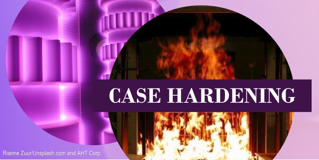
Case hardening is an essential process for many heat treating operations, but knowing the different types and functions of each is far from intuitive.
In this best of the web article, discover the differences between carburization, carbonitriding, nitriding, and nitrocarburizing, as well as what questions you should ask before considering case hardening. You will encounter technical descriptions and expert advice to guide your selection of which case hardening process will be most beneficial for your specific heat treat needs.
An excerpt:
Case hardening heat treatments, which includes nitriding, nitrocarburizing, carburizing, and carbonitriding, alter a part’s chemical composition and focus on its surface properties. These processes create hardened surface layers ranging from 0.01 to 0.25 in. deep, depending on processing times and temperatures. Making the hardened layer thicker incurs higher costs due to additional processing times, but the part’s extended wear life can quickly justify additional processing costs. Material experts can apply these processes to provide the most cost-effective parts for specific applications.
What makes the geometry of a part “complex”? With the increasing use of AM and 3D printing for parts along with typically complex parts, heat treaters in many industries must acquire the equipment and technical know-how for precise applications.
This Technical Tuesday article is compiled from Heat TreatTodayarticles and industry news releases. Email Bethany Leone at bethany@heattreattoday.com or click the Reader Feedback button below to chime in on the topic.
What Are Complex Geometries?
Contact us with your Reader Feedback!
Complex geometries in industrial parts are often defined by their intricate patterns and structures, which entail specialized heat treat processing. As Inductoheat describes in a case study with Stellantis, “Many times, complex geometries of components are linked to intricate hardness patterns and specific requirements for magnitude and distribution of residual stresses.”
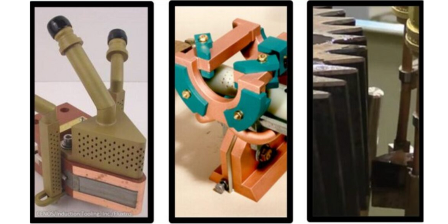
Heat Treat Equipment for Processing Parts with Complex Geometries
Be it for highly customized medical implants or for engine components in the burgeoning electric vehicle industry, complex geometries need to heat treated carefully. Fasteners in the medical device industry can be quite intricate and susceptible to creep or other dimensional changes; one method heat treating these parts — particularly titanium alloy parts — would be in a vacuum furnace. In vacuum and in hot isostatic presses, the environment allows for complex geometries that are 3D printed to be made into a unified whole piece. “Heat conduction can be carefully monitored [in induction heating coils] to confirm that an overheat condition does not occur at the target temper areas,” making induction a key candidate for heat treating your parts with complex geometries (“Tempering: 4 Perspectives — Which makes sense for you?“). To accommodate the complexities of certain parts, designing an induction coil for the desired case hardening may entail simulation to “[predict] coil heating, which altogether results in a longer coil lifetime,” (“Simulation Software and 3D Printers Improve Copper Coils”). For more on induction coils, check out this article by Dr. Valery Rudnev.
Suffice it to say, there is a great diversity of heat treatment options to explore when it comes to identifying the appropriate equipment for your application.
What Processes Are Used in Heat Treating Complex Geometries?
Perhaps you have all of your equipment needs necessary for heat treating your parts with complex geometries. Are you completing your heat treat processing in the most technically sound manner? Check out the following excerpts that speak to processing complex geometries.
“[Forging] at elevated temperatures enables reaching high strains and forming complex geometries in a single stroke. Additionally, thermal and mechanical influence during the forging can lead to improving local mechanical properties and the quality of the resulting joining zone.” (“Thermomechanical Processing for Creating Bi-Metal Bearing Bushings“)
“In some cases, such attempts result in a component’s geometries that might be prone to cracking during heat treating or might be associated with excessive distortion . . . . The subject of induction hardening of complex geometry parts (including but not limited to gears, gear-like and shaft-like parts, raceways, camshafts, and other critical components) is also thoroughly discussed, describing inventions and innovations that have occurred in the last three to five years.” (“Heat Treat Training Benefits Stellantis“)
“LPC [low pressure carburizing] with gas quenching can be an attractive option for distortion prone complex geometries as the cooling rates are slower than oil quenching; however, given the slower cooling rate, it becomes very important to choose a higher alloyed steel that will achieve the desired hardness.” (“Elevate Your Knowledge: 5 Need-to-Know Case Hardening Processes“)
Complex Geometries In the News
See how your peers are solving complex geometries needs in these real-life partnerships with industry suppliers. From additive manufacturing (AM) and precision manufacturing parts to heat treat technology, maybe your company is next to leverage manufacturing equipment to “wow” the industry.
On site at heat treat operations, gas-fired furnaces can be a significant source of carbon emissions. But depending on the desired heat treatment, an alternative approach that combines induction through heating and intensive quenching could be the “green ticket.” Learn about the ITH + IQ technique and discover how certain steels may benefit from this approach.
This Technical Tuesday article was composed by Edward Rylicki, Vice President Technology, and Chris Pedder, Technical Manager Heat Treat Products and Services, at Ajax TOCCO Magnethermic Corp., and Michael Aronov, CEO, IQ Technologies, Inc.It appears in Heat Treat Today's May 2023 Sustainable Heat Treat Technologiesprint edition.
Introduction
Chris Pedder, Technical Manager Heat Treat Products and Services, Ajax TOCCO Magnethermic Corp. Source: Ajax TOCCO Magnethermic Corp.
Induction heating is a green, environmentally friendly technology providing energy savings and much greater heating rates compared to other furnace heating methods. Other advantages of induction heating include improved automation and control, reduced floor space, and cleaner working conditions. Induction heating is widely used in the forging industry for heating billets prior to plastic deformation. Induction heating is also used for different heat treatment operations such as surface and through hardening, tempering, stress relieving, normalizing, and annealing. However, the amount of steel products subjected to induction heating in the heat treating industry is much less compared to that processed in gas-fired furnaces.
Contact us with your Reader Feedback!
Gas-fired heat treating equipment is a major source of carbon emissions in the industry. As shown in Reference 1, induction through heating (ITH) followed by intensive quenching (IQ) (an “ITH + IQ” technique) eliminates, in many cases, the need for a gas-fired furnace when conducting through hardening and carburizing processes — the two most widely used heat treating operations for certain steel parts. Eliminating gas-fired furnaces will result in significant reduction of carbon emissions at on-site heat treat operations.
Dr. Michael Aronov, CEO, IQ Technologies, Inc. Source: Ajax TOCCO Magnethermic Corp.
The goal of this article is twofold: 1) to evaluate carbon emissions generated during through hardening of steel parts and carburizing processes when conducted in gas-fired furnaces, and 2) to discuss how these emissions can be reduced to zero using the ITH + IQ process.
Evaluation of Carbon Emissions for Through Hardening and Carburizing Processes
Ed Rylicki, Vice President Technology, Ajax TOCCO Detroit Development & Support Center Source: Ajax TOCCO Magnethermic Corp.
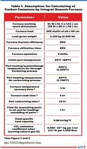
Most through hardening and carburizing operations for steel parts are conducted in batch and continuous integral quench gas-fired furnaces. Assumptions made for evaluating CO2 emissions produced by a typical integral quench furnace are presented in Table 1. Note: The values of carbon emissions presented Table 1 are conservative since they don’t consider the amount of CO2 produced by furnace flame screens and endothermic gas generators used to provide a controlled carburizing atmosphere in the furnace. Also, it’s assumed that the furnace walls are already heated through when loading the parts, so there are no heat losses associated with the thermal energy accumulated by the furnace walls.
Table 1. Assumptions for calculating of carbon emissions by integral quench furnace Source: Ajax TOCCO Magnethermic Corp.
Emissions Generated During the Through Hardening Process
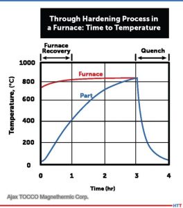
A furnace time/temperature diagram for the through hardening process considered is presented in Figure 1. Carbon emissions Ehard produced by the furnace considered during heating of the load to the austenitizing temperature prior to quenching are calculated by using the following equation,
(Equation 1) Ehard = k • Qhard
where:
■ k = the emission coefficient (equal to 0.050 • 10-3 kg per 1 kJ of released energy when burning natural gas (see Reference 2) ■ Qhard = thermal energy required for heating up the above load from ambient to the austenitizing temperature
A value of Qhard is calculated by the equation below,
■ M = load weight, kg ■ C = steel specific heat capacity (kJ/kg°C) ■ Ta = part austenitizing temperature (°C) ■ To = part initial temperature (°C) ■ Eff = furnace thermal efficiency (a ratio of the furnace thermal losses to the gross heat input)
From equations (1) and (2), the amount of carbon emissions produced by the above furnace during one hardening operation is 40.2 kg. To determine an annual amount of carbon emissions, calculate the number of hardening cycles per year (Nhard) run in the furnace. From Figure 1, a duration of one hardening cycle is 4 hours (3 hours for austenitizing of the parts plus 1 hour for quenching the parts in oil and unloading/loading the furnace). Thus, Nhard is equal to:
Nhard = 360 day • 24 hour • 0.85 / 4 hour = 1826
Figure 1 Source: Ajax TOCCO Magnethermic Corp.
Annual CO2 emissions from one integral quench batch gas-fired furnace are 40.2 • 1836 = 73,807 kg, or more than 73 t
Emissions Generated During Carburizing Process
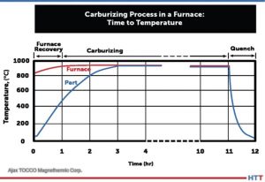
A simplified furnace time/temperature diagram for the carburizing process considered is presented in Figure 2. Carbon emissions (Ecarb) produced by the above furnace during the carburizing process are calculated by the following equation,
(Equation 3)
Ecarb = k • Qcarb
where:
■ Qcarb = a thermal energy expended by the furnace during the carburizing process. A value of Qcarb amounts to two components:
(Equation 4)
Qcarb = Qcarb1 + Qcarb2
Qcarb in the following equation is:
■ Qcarb1 = energy required for heating up the load to the carburizing temperature
■ Qcarb2 = energy needed for maintaining the furnace temperature during the remaining duration of the carburization process (for compensation of the furnace thermal losses since the parts are already heated up to the carburizing temperature)
A value of Qcarb1 is calculated using equation (2) where the part carburizing temperature Tc is used instead of part austenitizing temperature Ta (see Table 1):
A value of Qcarb2 is a sum of the flue gas losses and losses of the thermal energy through the furnace walls by heat conduction. Qcarb2 is evaluated from the following considerations. Since the assumed furnace thermal efficiency is 65%, the furnace heat losses are equal to 35% of the gross heat input to the furnace. Hence, the furnace heat losses Qloss1 during the load heat up period (the first 3 hours of the carburizing cycle, see Figure 2) are the following:
Thus, the total amount of the thermal energy expended by the furnace during the carburizing cycle is Qcarb = 0.887 • 106 + 0.827 • 106 = 1.71 • 106 kJ. The total amount of the CO2 emissions from carburizing of the load in the furnace considered according to equation (3) is: Ecarb = 0.050 • 10-3 • 1.71 • 106 = 85.7 kg. To determine an annual amount of carbon emissions from one carburizing furnace, calculate the number of carburizing cycles run in the furnace per year. Per Figure 2, a duration of one carburizing cycle is 12 hour (1 hour for the furnace recovery plus 10 hour for carburizing of parts at 927°C plus 1 hour for quenching parts in oil and for unloading and loading the furnace). Thus, the number of carburizing cycles per year Ncarb is:
Ncarb = 360 day • 24 hr • 0.85 / 12 hr = 612
Figure 2 Source: Ajax TOCCO Magnethermic Corp.
Annual CO2 emissions from one integral quench batch carburizing furnace is about 85.7 • 612 = 52,448 kg, or more than 52 t.
Reducing Carbon Emissions Using the ITH + IQ Process
Reference 1 presents results of two case studies of the ITH + IQ process on automotive input shafts and drive pinions. The study was conducted with a major U.S. automotive part supplier. A two-step heat treating process was used for the input shafts, consisting of batch quenching parts in oil or polymer using an integral quench gas-fired furnace for core hardening followed by induction hardening. This two-step method of heat treatment is widely used in the industry for many steel products. It provides parts with a hard case and tough, ductile core.
Substituting the “ITH + IQ” method for the two-step heat treating process not only eliminates the batch hardening process, but also requires less alloy steel for the shafts that don’t require annealing after forging. Thus, in this case, applying the ITH + IQ technique eliminates two furnace heating processes for the input shafts, resulting in the reduction of the CO2 emissions to zero for the shafts’ heat treatment. Per client evaluation, as mentioned in Reference 1, the hardness profile in the intensively quenched input shafts was similar to that of the standard shafts. Residual surface compressive stresses in the intensively quenched shafts were greater in most cases compared to that of the standard input shafts, resulting in a longer part fatigue life of up to 300%.
Per Reference 1, the environmentally unfriendly carburizing process can be fully eliminated in most cases for automotive pinions when applying the ITH + IQ method and using limited hardenability (LH) steels that have a very low amount of alloy elements. A case study conducted for drive pinions with one of the major U.S. automotive parts suppliers demonstrates the intensively quenched drive pinions met all client’s metallurgical specifications and passed both the ultimate strength test and the fatigue test. It was shown that the part’s fatigue resistance improved by about 150% compared to that of standard carburized and quenched in oil drive pinions. In addition, distortion of the intensively quenched drive pinions is so low that no part straitening operations were required.
Conclusion
Coupling Ajax TOCCO’s induction through heating method with the intensive quenching process creates a significant reduction of CO2 emissions produced during heat treatment operations for steel parts. For the through hardening process, eliminating just one batch integral quench gas-fi red furnace will reduce carbon emissions by more than 73 ton per year. For the carburizing process, eliminating just one batch carburizing furnace will reduce carbon emissions by more than 52 ton per year. Note that for continuous gas-fired furnaces, the carbon emission reduction will be much greater due to higher continuous furnaces production rates (hence a much higher fuel consumption).
Per our experience, the ITH + IQ process can be applied to at least 20% of the currently through-hardened and carburized steel parts. Per two major heat treating furnace manufacturers in the U.S., there are thousands of atmosphere integral quench batch and continuous furnaces in operation in the U.S. That means hundreds of gas-fired heat treating furnaces can be potentially eliminated, drastically reducing carbon emissions in the U.S., supporting a lean and green economy.
Ed Rylicki has been in the induction heating industry for over 50 years. He is currently Vice President Technology at Ajax TOCCO Detroit Development & Support Center in Madison Heights, Michigan.
Mr. Chris Pedder has over 34 years of experience at Ajax Tocco Magnethermic involving the development of induction processes in the heat treating industry from tooling concept and process development to production implementation.
Dr. Michael Aronov has over 50 years’ experience in design and development of heating and cooling equipment and processes for heat treating applications. He is CEO of IQ Technologies, Inc. and a consultant to the parent company Ajax TOCCO Magnethermic.
There are many radiant tube options on the market, so which one is best for your furnace and your budget? In this column that compares radiant tubes in carburizing and continuous annealing furnaces, discover how two major types of radiant tubes stack up.
Marc Glasser, director of Metallurgical Services at Rolled Alloys, investigates more deeply the two choices. This Technical Tuesday discussion on radiant tubes options will be published inHeat Treat Today'sFebruary 2023 Air & Atmosphere Heat Treating Systems digital edition.
Introduction
Marc Glasser Director of Metallurgical Services Rolled Alloys Source: Rolled Alloys
Radiant tubes are used in many types of heat treating furnaces from carburizing furnaces to continuous annealing of steel strip. Generally, a heat treater has three options for radiant tubes: cast tubes, wrought tubes, and ceramic silicon carbide tubes. Silicon carbide tubes are rarely used by heat treaters, so this article will not delve too deeply into this option. Suffice it to say, ceramic materials can often handle much higher temperatures at the expense of ductility; ceramics are more brittle than metals, making them prone to failure from the small impacts, so metal cages are sometimes fabricated to protect them. Most of the tubes being used today are cast radiant tubes. With new casting technology — primarily centrifugal casting — thinner tubes are being cast at a lower cost, which then results in a shorter life.
The primary factors for choosing radiant tube material are tube temperature and carbon potential of the furnace atmosphere. Cost-benefit analysis should also be considered. There are multiple applications for radiant tubes, including carburizing furnaces, continuous annealing furnaces for steel sheet galvanizing, steel reheat furnaces, and aluminum heat treating. This article will explore two of the aforementioned radiant tube options, specifically for carburizing and continuous annealing furnaces.
Radiant Tubes for Carburizing Furnaces
Gas carburization is traditionally performed between 1650°F and 1700°F at a carbon potential of 0.8% approximating the eutectoid composition. In today’s competitive environment, more heat treaters are increasing temperatures to 1750°F and pushing carbon potentials as high as 1.6% to get faster diffusion of carbon while spending less time at temperature. INCONEL® HX (66% Ni, 17% Cr) has been a common cast alloy seen in carburizing furnaces. This alloy is regularly selected for its resistance to oxidation and carburization up to 2100°F. Super 22H is more heavily alloyed than HX and is seeing more use as carbon potentials increase but at a premium price. With advances in centrifugal castings, cast tube wall thicknesses have decreased from 3/8-inch to 1/4-inch. Some heat treaters have shared that this decrease in wall thickness has also led to shorter tube life.
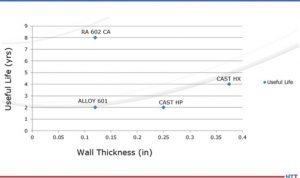
Fabricated and welded radiant tubes in alloys 601 and RA 602 CA® have been tested in industry. When tested, these wrought alloys were fabricated to have a wall thickness of 1/8-inch. At the extremes, tubes fabricated from 601 only lasted 50% as long as cast HX. Historically, HX tubes have been approximately 33% higher in cost than that of 601 and utilize heavier 3/8-inch walls. A little-known fact is that by switching to a thinner wall cast tube, the life drops by 50%. By switching to 1/8-inch wall thickness, RA 602 CA tube life has been extended to eight years or more, while running at 1750°F and up to 1.6% carbon potential, at just a 33% premium over cast HX. Life cycle data are presented in Figure 1.
Figure 1. These life cycle comparisons were done in carburizing furnaces only. In non-carburizing furnaces, justification of alloy selection is dependent on actual operating conditions and each individual operator’s own experience. Source: Rolled Alloys
Radiant Tubes for Continuous Annealing Furnaces
In the area of continuous annealing, the cast alloy of choice is HP/HT (35% Ni, 17% Cr, 1.7% Si, 0.5% C). Here again, this casting has been compared to 601 and RA 602 CA, with the same results. The total life data from these trials are also incorporated into Figure 1. During the collection of this data, there has been no effort to measure the actual tube temperature, so the effect of tube temperature is not clearly defined. In these continuous annealing furnaces, it has been reported that the tubes at the entry end are subject to more heat absorption as burners are firing more due to the continuous introduction of cold material; in trials, the operators have not kept adequate documentation of specific tubes, making justification more diffcult.
Justification for the higher cost wrought alloy needs to take into consideration initial fabricated tube cost, actual tube life, AND the lost production of each anticipated downtime cycle as these downtime costs are often much more than material costs. Only individual fabricators can determine these costs.
The Economics
Table 1 Source: Rolled Alloys
Table 1 above shows the economics of metal alloy choice. To properly interpret, understand that the costs are not actual, but rather relative to 601, so a round number of 1000 was used. With a 30% greater cost of cast tubes, that translates to a relative cost of $1300. The annual cost is the amortized cost over the life of the tube. The total eight-year cost is the relative cost times the number of tubes that would have to be purchased to obtain the life cycle of one tube of the longest-lasting material over its full life cycle.
Missing in this analysis is the additional cost of downtime and lost production. For the replacement of radiant tubes in a carburizing furnace, this typically entails a full week to turn a furnace off, allow it to cool, replace the tubes, and then heat it up again. Many heat treaters do not consider this, and therefore it is a hidden cost. Even without the downtime being considered, by examining the total cost of materials (including replacements) compared to the longest-lasting tube, it turns out that the most expensive tube is the cheapest tube. The obstacle to overcome is whether the heat treater is willing to wait eight years to realize these cost savings.
There can be additional factors to consider. With improvements in the efficiency of casting, the actual costs of the thinner wall casting may be somewhat less, but to match the overall cost of the longest-life material, it would have to be less than half the expected cost. As better, more expensive cast alloys become accepted and actual life data becomes available, these more costly alloys can be added to this table for comparative analysis, too.
This same method of analysis can be applied to radiant tubes for continuous annealing furnaces, but more details will need to be added including furnace position. Different alloy candidates will have to be put to the test in actual operations, carefully document what alloy is in what position or location, and when it gets changed out. This becomes quite cumbersome when annealing furnaces (depending on design and manufacture) can have over 200 radiant tubes.
Conclusion
Currently, cast alloy tubes dominate the market. The concept of total life cycle cost has been introduced as a means of more accurately justifying one’s choice of radiant tube. This comes into play more as processes are pushed beyond traditional process conditions. Cost-benefit analysis must be balanced over acceptable amortization time, of course. However, performing the full analysis as well as the costs saved from downtime may lead some heat treaters to some alternate materials.
About the author: Marc Glasser is the director of Metallurgical Services at Rolled Alloys and is an expert in process metallurgy, heat treatment, materials of construction, and materials science and testing. Marc received his bachelor’s degree in materials engineering from Rensselaer Polytechnic Institute and a master’s degree in material science from Polytechnic University, now known as the NYU School of Engineering. Contact Marc at mglasser@rolledalloys.com
Find heat treating products and services when you search on Heat Treat Buyers Guide.com
Get ready to watch, listen, and learn about the three most underrated heat treat processes in today’s episode. This conversation marks the continuation of Lunch & Learn, aHeat Treat Radio podcast series where an expert in the industry breaks down a heat treat fundamental with Doug Glenn, publisher of Heat Treat Today and host of the podcast, and the Heat Treat Today team.
Below, you can watch the video, listen to the podcast by clicking on the audio play button, or read an edited transcript.
The following transcript has been edited for your reading enjoyment.
Doug Glenn: There are some underdog heat treat processes out here. I’d like to get to three today. What do you think is number one?
Michael Mouilleseaux: Let’s start with stress relieving. All ferrous materials, all steels, during the course of manufacturing or processing, have some residual stress that is left in them. A common thought about stress relieving is you have a weldment, and you stress relieve it so that the weldment stays.
Contact us with your Reader Feedback!
There is a mechanical action in the material during any cold working operation (cold forging, stamping, fine planking, etc.) because it's done at ambient temperature. Those all impart stress on the part.
Machining, turning, grinding. . . all of those things impart stress into a part. How is that relieved? It can be done thermally, or it can also be done mechanically. Thermally is the most common of them.
What I would like to talk about is not so much stress relieving weldments, it is stress relieving manufactured components. If you’re going to have a comprehensive analysis of the heat treat operation that needs to be performed on a manufactured component, a gear, a shaft, something of that nature, they need to take into consideration what are the prior existing stresses in the part. Then what effect is that going to have on the part?
Many times during the course of my career, I’ve had a customer come to me and say, “The part I gave you was correct, and you’ve given it back to me and then fill-in-the-blank. It’s warped, it’s changed size, it’s shrunk, all of those things.” What have you done in your heat-treating process? You have to back up all the way to the beginning of how this part was manufactured and deal with all of those component steps in order to answer that question properly.
Stress relieving is one of the answers. It’s not the answer. It’s not the only answer, but it is one of them that has to be considered.
"Stress Relieving Tips from Heat TreatToday"
Doug Glenn: For those of us who might not know what a “stress” is in a part, can you simply explain? For example: a coat hanger. If I bend it, is that inducing stress? Is that what’s causing stress? What makes stress in a part?
Michael Mouilleseaux: You’ve cold-worked the part. In the cold working, you’ve passed the yield strength. You’ve bent it, and it’s not going to snap back. You’ve cold-worked it enough that you’ve actually got plastic deformation, and there is stress.
Doug Glenn: That’s one way we get stress. That’s the mechanical way of getting stress.
Michael Mouilleseaux: Right. Now, consider stamping. Even though a stamping is flat (because the die has come down in the perimeter of that and maybe internal holes and things), where you’ve sheared the material, you’ve imparted stress there.
If you harden it or case harden it or whatever you might do with that stamping, you have to take into consideration how much stress is there. If I don’t relieve it, is it going to do that at some point in the part’s future that’s going to be detrimental to the part?
Doug Glenn: When you get a stress in a part, that’s the area that’s a weak spot, right? It potentially could break before other parts?
Michael Mouilleseaux: At the absolute extreme, that could happen, yes. More often than not, what you have is an area that’s been cold worked, and it’s been deformed. When it stresses, it’s going to somewhat relieve itself. It may not relieve itself 100% all the way, but it will somewhat relieve itself. Whatever shape of form you’ve put that part into; it’s not going to hold that form forever.
Alyssa Bootsma: You mentioned that stress relieving is not the only way to alleviate the problems. What would be some alternatives to stress relieving?
Michael Mouilleseaux: Thermal stress relieving is, by far, the most common. There is a process that’s called vibratory stress relieving. In order to relieve the stresses in a part, you have to impart some energy in it. Something between 800 and 1200 Fahrenheit is typically used in stress relieving. That thermal energy goes into the part and relieves the stresses.
You could also do that mechanically by a high frequency vibration. It’s not as common. I believe that it’s actually a propriety process, if not patented. It would be for something that you did not want to subject to 800-1000 degrees Fahrenheit because that doesn’t come for free. Obviously, in a ferrous material at that temperature, you’re going to have some oxide forming on the part. You may or may not be able to utilize the part in its final function with that oxide on it.
Those are typically the two ways to do it. Can it occur naturally over time? Yes, but none of us have that kind of time.
Alyssa Bootsma: You did mention how it doesn’t necessarily mean that it’s more likely to break if that part is not relieved, but what parts would suffer the most if this process was done incorrectly?
Michael Mouilleseaux: Probably weldments. The detrimental effects of not having stress relieved of weldment would be the most significant. In welding there is a whole range of temperatures proximate to the weld — everything from room temperature to maybe 3000 degrees. That whole range of things changes the structure of the steel.
Leaving it in that condition makes it susceptible to any number of things — embrittlement, accelerated corrosion, and others. There is every reason to stress relieve something like that and almost no reason not to.
Doug Glenn: That’s weldment. Do they do a stress relieve after a braze as well, or is that not as common?
Michael Mouilleseaux: Typically not. The reason for that is, in brazing, the entire assembly is brought up to the same temperature. Then it’s cooled at the same rate.
Bethany Leone: I have two brief questions: 1. How long does stress relieving typically take? 2. Would we see the effects of incorrect stress relieving, or failure to, once something goes to quench?
Michael Mouilleseaux: The first question — would you necessarily see a failure? Those would be extremes. I’m more familiar with stress relieving fabricated components that are machined. Take a gear. They forge a blank and maybe machine out the center of the gear, machine the exterior of the gear, cut the teeth in a shaping operation (a hobbing operation or skiving or other ways of generating teeth).
"You have this part, and it needs to be heat treated. To assume that all of those machining operations would have no effect upon that whatsoever is not a good thought."
Then comes a comprehensive program of evaluating how best to heat treat a part. It doesn’t matter if it’s out of a medium carbon alloy steel or it’s a low alloy steel and we’re going to carburize it, what’s critical is that it’s going to get heated. The material is going to transform into austenite and cool rapidly or quench it. That’s what’s going to cause the hardening operation on the part.
In doing that, there are going to be changes in size. In hardening a part, you get a volumetric expansion. Thin sections are not going to expand as much as larger sections. A misnomer is, “You shrunk the hole.” You haven’t shrunk the hole! The material around the hole has expanded, the exterior portion of that area has increased, and the interior portion of that has decreased.
If you have a spline in that hole, now you’re on for something else because their teeth form in that spline. If it’s in a long section, then how uniform it’s been hardened has to do with whether or not it goes out of round or their taper. There are any number of things there. Those are all critical to the operation of this gear.
But what we have to take into consideration is the broaching operation. We drill a hole, and we put a broach bar through it and cut all of these teeth. All of that has imparted stress in the part.
One of the preliminary things that needs to be done is you stress relieve the part and give it back to the manufacturer. They measure it and say, “Oh, oh, it changed!” That change is not something the heat treater can do anything about. That’s the physics of what happens when you work-harden a part. This all has to be taken into consideration and addressed before we talk about what’s the heat treat distortion.
Bethany Leone: And the other question I had: How long does it take to stress relieve?
Michael Mouilleseaux: Typically, if it’s held at an hour or two at temperature, it’s thought that 1000 degrees for an hour at temperature will relieve most stresses.
Now, in a component part, we’re going to go higher in temperature. Although we’re not going to go high enough to austenitize the part, we’re going to go high enough in temperature that we know we’re going to relieve it.
Michael Mouilleseaux: They’re cousins. Stress relieving, the implication is that you are doing that simply to relieve prior existing stresses. In annealing, the implication is that you are going to reduce the hardness of the microstructure for the purposes of machining or forming. In annealing, there’s subcritical and supercritical and a hundred different flavors of that.
Doug Glenn: I’m trying to get a sense of what percentage of heat treating is stress relieving. Is it super popular? It seems to me it would be very common.
Michael Mouilleseaux: Interestingly enough, I’m going to say that the majority of the gearing product that we do, we incorporate a stress relief in the initial stages of heat treating. By putting the part in and raising the temperature to a stress relieving temperature and then taking it up into the austenitizing temperature, you’re not shocking the part. You’re not just taking it from room temperature to carburizing temperature or hardening temperature, and thereby you’re reducing the thermal stresses. So, you’re not imparting any more.
Doug Glenn: Stress relieving may often be done as a part of another process?
Michael Mouilleseaux: It can be, definitely.
Doug Glenn: Let’s move on to the second forgotten heat treatment.
Michael Mouilleseaux: I don’t know about forgotten. I’m going to say that it’s getting short shrift, and that is conventional atmosphere carburizing. What’s sexy in heat treating? It’s low pressure carburizing and gas quenching. It’s growing very rapidly and it’s being used in a lot of applications.
We’re subject to the same ills that Mark Twain identified years ago, and that is, “To a man with a hammer, every problem looks like a nail.” Low pressure carburizing and gas quenching, they can save every distortion issue that’s ever been known to man in heat treating, and they don’t. They are other tools in the box, applicable to a lot of application. They are great processes, very targeted and specific. You know, sometimes you need a screwdriver instead of a hammer.
Conventional carburizing: It’s been around for a hundred years. What’s different today than what it ever was? Certainly it has everything to do with the control systems that are being used to control it. It’s eminently more controllable now than it has ever been. It is a precision operation, and it has many applications. By the way, it’s far more cost effective than carburizing would be. In vacuum carburizing, the cost is multiple; is it two, three or four times more expensive? It depends on how you calculate cost of capital and all of those things. But it’s a multiple, more expensive than conventional carburizing.
Doug Glenn: To do vacuum carburizing?
Michael Mouilleseaux: To do vacuum carburizing, yes. Should it be used in every application? I’m going to say no. Are there definite applications? Definitely.
Doug Glenn: Conventional carburizing, atmosphere carburizing is another area largely forgotten. I know it’s quite popular, but it’s not getting a lot of discussion these days.
Michael Mouilleseaux: Right. Any time there is an issue with a carburized part, everyone knows to ask the question, “Why don’t you vacuum carburize it?” The answer to that is, “Let’s solve the problem before we decide what it is that we need to do.”
Karen Gantzer: Mike: At a very basic level, can you explain why do heat treaters use endothermic gas?
Michael Mouilleseaux: In atmosphere carburizing, we need a method of conveying carbon to the part so that we can enrich it; that’s what carburizing is. The carburizing portion of the atmosphere in endothermic gas is carbon monoxide. Carbon monoxide — that’s the reaction at the surface of the part — the carbon diffuses into the part. That’s how you generate a case in the part.
It’s a relatively inexpensive form of carburizing. You use natural gas and air in what we call a “generator”, and that’s how endothermic gas is generated. Then, it’s put into the furnace. There’s almost no air in a furnace. People think you’re going to look in a furnace, and you’re going to see flame. You never do because the amount of oxygen in the furnace is measured in parts per million. You put additional natural gas to boost the carburizing potential of the atmosphere, and that’s what allows you to diffuse carbon into the part. That is the case hardening process.
Doug Glenn: Conventional carburizing is done in a protective atmosphere, typically as an endothermic atmosphere which is rich in carbon monoxide.
Michael Mouilleseaux: Yes.
Doug Glenn: A lot of times we’re worried about oxygen in the process because of potential oxidation. Why is it that we use a gas that has oxygen in it to infuse carbon? I know it’s got carbon, but it’s also one C and one O, right? Don’t we run into problems of potential oxidation?
"Comparative Study of Carburizing vs. Induction Hardening of Gears"
Michael Mouilleseaux: In endothermic gas there is hydrogen, nitrogen and carbon monoxide, and there are fractional percentages of carbon dioxide and some other things. The hydrogen is what scrubs the part; that’s what kind of takes care of all of the excess oxygen. The nitrogen is just a carrier portion of it, and the carbon monoxide is what is the active ingredient, if you will, in the carburizing process.
The carbon diffuses into the part. If there is an oxygen, it’s going to combine with the hydrogen. Preferentially, you’re not going to have any free oxygen in the furnace, but you can have a little water vapor. One of the ways of measuring the carbon potential in the furnace is a dewpoint meter. The dewpoint meter is measuring the temperature at which the gas precipitates out, and that’s a monitor or a measure of the carbon potential.
Doug Glenn: A dewpoint analyzer helps you know what the carbon potential is.
Michael Mouilleseaux: Yes. It’s not as good as an oxygen analyzer.
Doug Glenn: An oxygen probe.
Michael Mouilleseaux: The oxygen probe is in the furnace, measuring constantly. You get a picture; you have continuous information. It’s not that there aren’t continuous dewpoint analyzers, but you have to take a sample from the furnace. It has to be taken to an analyzer wherein it is then tested. Best case scenario is you have both of them and you compare the two of them. That gives you a really great picture of what the atmosphere conditions are in the furnace.
Alyssa Bootsma: For a bit of background knowledge: What is the difference between endothermic gas and exothermic gas?
Michael Mouilleseaux: Endothermic gas has 40% hydrogen and 20% carbon monoxide. 60% of it is what you would call a reducing atmosphere. The way that you make endothermic atmosphere is 2.7 parts of natural gas and one part of air. You heat it up to 1900 degrees, and it’s put through a nickel catalyst. You strip off the hydrogens. The gas dissociates, and that’s what results.
Exothermic gas is six parts of air in one part of natural gas. You only have 10 or 15% hydrogen. Although it’s not an oxidizing atmosphere, it’s very mildly reducing.
It can be used in annealing, clean annealing. If you’re annealing at 12-1300 degrees or more or in that ballpark, that kind of an atmosphere is going to keep the work clean. If you did it in air, it would scale.
Bethany Leone: Is there an industry (automotive, aerospace, energy) that it would be most helpful for those parts to be typically atmosphere carburized, and/or is it just generally helpful for all types of industries?
Michael Mouilleseaux: First of all, the transportation industry is the lion’s share of heat treating — automotive, truck, aircraft. Atmosphere carburizing is extremely popular and commonplace in those industries.
If we said that we were going to have a seminar and I’m going to talk about atmosphere carburizing. Somebody else is going to talk about low pressure carburizing in a vacuum furnace. Everybody’s going to go over to the other room. Folks feel they already know what this is all about, and they know what all the problems are. They think that the vacuum carburizing is going to solve all of them.
When you work with the proper kinds of controls, the proper kinds of furnace conditions, the right way of fixturing parts and cleaning them ahead of time, you can have extremely consistent results. You can have extremely clean parts, and you can have very good performance from these things.
What the Europeans call “serial production”: we run millions of gears per year, and we have very consistent case steps in hardnesses as a result of good practice. All of these things need to be monitored and controlled and taken care of. But the results are also very consistent and very predictable.
Doug Glenn: Interesting. And it’s more cost-effective, I’m guessing. Conventional atmosphere carburizing, on a per part basis, is going to be substantially less expensive.
Michael Mouilleseaux: We’ve looked at it. Is it two times, is it three times, is it four times more expensive to vacuum carburize a part? The answer is yes. The question is, does that component justify that? There are any number of them where it does.
Doug Glenn: Where it does justify it?
Michael Mouilleseaux: Yes, absolutely.
Doug Glenn: Let’s go on to #3, the third underdog in heat treating.
Michael Mouilleseaux: Number three is marquenching. Marquenching, martempering, and hot oil quenching are in the family that describes this process.
Martempering is different than just quenching in oil, quenching in regular fast oil. Regular oil is going to be 100 vis, and it’s going to be from 90 degrees to 150 degrees. All kinds of low hardenability, or parts that don’t have a lot of adherent alloy in them, you utilize that so that they can be fully hardened. But components that are distortion-critical, quenched in that manner in regular oil, there is going to be a high degree of distortion. How is that addressed? It’s addressed in marquenching.
Let’s take an example of a carburized gear. A carburized case is heated to 16-1700 degrees and carburized. Best practice would say that I’m going to reduce the temperature before I quench it, and then I’m going to quench it in oil. Do I understand that: I have to have loading that spaces the part; and the parts need to be fixtured in such a way that, physically, they don’t impede on each other; and I get full flow of oil, and all of those things? The answer is yes, yes, and yes.
The martensite starts to form in the case at, let’s say, 450 and it’s plus or minus 25 or 30 degrees or so. Take that part and put it into the range where the martensite starts to form, and hold it at that temperature and let the entire part cool down to that 450 degrees where the martensite is starting to form. Then we remove the part from the furnace and allow it to cool in air to room temperature. At that point, the cooling rate is much lower than it it’s going to be where you’re conducting that in a liquid medium. Because of that, the stresses are going to be less, the distortion is going to be less. That is a strategy for reducing distortion.
You ask, “Why do you need to do that.?” Again, the man with the hammer: I’m going to gas quench this part because I have the opportunity to gas quench it, and the gas quenching doesn’t come for free. The shadowing effects of a gas flow has to be taken into consideration, orientation of the parts. There are a number of things that need to be taken into consideration.[blocktext align="left"]There are a number of applications where in marquenching a part, the distortion can be controlled. We process a lot of gears, and we maintain 20/30 microns of total distortion in ID bores on gears. It is a viable way of controlling distortion.[/blocktext]
Doug Glenn: We say marquenching.
Mike Mouilleseaux: Or martempering or hot oil quenching.
Doug Glenn: The “mar” part of that comes from martensite? I want have you explain what exactly martensite is. But is that where it comes from?
Mike Mouilleseaux: Yes. We’re getting right into the start of the martensite transformation.
Doug Glenn: There are different microstructures in metals. Austenite is pretty much the highest temperature, and it’s where the molecules are almost “free floating.” They’re not liquid, but they can move around. (This is very layman’s terms.) That’s austenite.
What causes distortion is when you’re cooling from austenite down to the point where that thing is, kind of, locked in; that can cause distortion in there because the molecules are still free to move. Some areas cool faster than others, and when you have that, you can get twists and turns or bulges. Once it gets down to the martensite temperature, that’s when things are, locked in. Is that fair?
Michael Mouilleseaux: The other thing that happens is you’re going from a cubic structure to a tetragonal structure. You’re asking, “Why are we there?” That’s where the expansion comes. The close-packed tetragonal structure takes up more volume than the austenitic or cubic structure. That’s where the volumetric expansion takes place.
Doug Glenn: At a higher temperature, the molecules are arranged in such a way that they take up more space; there’s more space between them.
In the cooling process with marquenching, if you bring it down just to the point where it’s, what Mike referred to as, the ‘martensite start temperature,’ that’s the temperature where things are just locking in. But it’s not so drastic that you’re dropping way down in temperature so that there are larger temperature differentials and things are really starting to get torqued out of contortion because of the difference in the cooling rates in the part.
Michael Mouilleseaux: The other part of that is that the formation of martensite is not time dependent. It’s not like you would have to hold it at 400 degrees for a longer period of time than you would at 200 degrees to get martensite. At 400 degrees, you’ve got some percentage of transformation. Say, it’s 30%. The transformation is temperature dependent. Because it’s temperature dependent, you can take it out and slow down the cooling rate. Then, as the transformation takes place, there is less stress, and if there’s less stress, then there is less distortion.
Again, it’s typically going to be distortion-sensitive parts.
The simplest geometric shape is a sphere. There aren’t any changes in section size in a sphere. It can be rotated, and you’ve got the same section size. You don’t have the kind of thing where one area is cooling more rapidly than another.
A major source of distortion is varying mass. Like a hole in a block: one portion of the block is two inches wide, and another portion is an inch wide. To think that that hole is going to stay straight all by itself, that won’t happen because there’s more mass around one end. By marquenching it and slowing down the transformation, you’re giving yourself an opportunity to reduce the amount of stress that’s generated. It’s the volumetric expansion in the thicker section than in the thinner section. Your opportunity to maintain that hole so that it stays round and it stays straight is much better. Otherwise, the thin section is going to completely transform before the thicker section does.
Doug Glenn: Transform to martensite or whatever, yes.
Michael Mouilleseaux: The extreme case in that is if that happens rapidly enough, and there’s a large enough differential in section size, the part cracks.
Doug Glenn: That’s the nightmare for the heat treater.
Guest Michael Mouilleseaux with the Heat TreatToday team
Bethany Leone: Are there any instances where it’s definite that another way to manage distortion would be better than marquenching?
Michael Mouilleseaux: Sure. Again, what’s currently sexy in this industry is gas quenching things. I’m going to say that cylindrical parts that have a thin wall, when properly gas quenched, will give you better distortion control, better size control than it would if you’d quench them in a liquid medium such as oil. We don’t want to forget that marquenching can be performed in salt, as well.
If we were going to talk about a fourth one, it might be salt quenching because that’s one of those things that’s not commonly utilized. There is some real opportunity with it.
Doug Glenn: Mike, thanks for ‘dumbing this down’ for us. We appreciate it! It’s sometimes a struggle to state things simply, but you did a great job.
Are there any closing thoughts you’d like to leave with us regarding the nearly-forgotten, popular heat treat processes, or anything else?
Michael Mouilleseaux: How about the combination of all three that I just spoke about?
Doug Glenn: Okay. Well, how about that?
Michael Mouilleseaux: I’ve got a distortion sensitive gear, and we’ve figured out that there is some stress in the part as a result of the final machining operation. We stress relieve the part, we carburize it conventionally, and then we marquench it. Those gears that I spoke about where we’ve got 20 or 30 microns of ID bore distortion — that’s exactly what’s done there.
Doug Glenn: Okay. Stress relieve first, conventional carburize, and then marquench. A combination of three.
Mike, thank you very much. This has been really helpful and it’s been good to learn a little bit on our Lunch &Learn. We’ll hope to have you back sometime to make other things understandable for us.
About the expert: Michael Mouilleseaux is general manager at Erie Steel LTD. Mike has been at Erie Steel in Toledo, OH since 2006 with previous metallurgical experience at New Process Gear in Syracuse, NY and as the Director of Technology in Marketing at FPM Heat Treating LLC in Elk Grove, IL. Having graduated from the University of Michigan with a degree in Metallurgical Engineering, Mike has proved his expertise in the field of heat treat, co-presenting at the 2019 Heat Treat show and currently serving on the Board of Trustees at the Metal Treating Institute.
Welcome to another Technical Tuesday for 18 hard-hitting resources to use at your heat treat shop. These include quick tables, data sets, and videos/downloadable reports covering a range of heat treat topics from case hardening and thermocouples to HIPing and powder metallurgy.
Defining Terms: Tables and Lists
Table #3 Suggested Tests and Frequencies for a Polymer Quench Solution (in article here)
Case Hardening Process Equipment Considerations (bottom of the article here)
Two simulations of a moving billet through heating systems (in article here)
Fourier’s Law of Heat Conduction (in article here)
Webinar on Parts Washing (link to full webinar at the top of the review article here)
Materials 101 Series from Mega Mechatronics, Part 4, Heat Treatment/Hardening here
Heat Treat TV: Press-and-Sinter Powder Metallurgy here
BONUS: 39 Top Heat Treat Resources
Heat Treat Today is always on the hunt for cutting-edge heat treat technology, trends, and resources that will help our audience become better informed. To find the top resources being used in the industry, we asked your colleagues. Discover their go-to resources that help them to hone their skills in the 39 Top Heat Treat Resources on this page of the September print magazine.
Your parts need heat treated to herculean surface hardness but with a soft, ductile core. That is to say, you are looking at case hardening processes, most likely one of these: gas carburizing, low-pressure carburizing, carbonitriding, gas nitriding, and ferritic nitrocarburizing.
Mike Harrison at Gasbarre Thermal Processing Systems brings us a Technical Tuesday article about what case hardening is and how five of the most common processes vary by (1) comparing the specific guidelines for each temp and time, (2) identifying equipment used to perform each process, and (3) providing a chart (at the end!) to understand different process considerations.
Mike Harrison Engineering Manager of Industrial Furnace Systems Division Gasbarre Thermal Processing Systems
Case hardening falls into a class of heat treatment processes that typically involve the addition of carbon and/or nitrogen to the material through solid-gas reactions at the surface followed by diffusion. These processes are performed for any number of reasons that generally include increasing strength and wear resistance, but in all cases the end result is a harder, higher-strength surface with a softer, more ductile core.
Case hardening processes can be divided into two subsets: those that include quenching to harden, such as gas carburizing, low-pressure carburizing (LPC), and carbonitriding; and those that do not include quenching, such as gas nitriding and ferritic nitrocarburizing (FNC). This article will provide a brief look into each process, the types of equipment used, and considerations for implementation.
Diffusion + Quenching Processes
These processes involve heating the workload to austenitizing temperature, which is above the upper critical temperature for the material in question, then supplying and allowing the desired element(s) to diffuse into the part surface, followed by rapid cooling (quenching) to create a phase change to martensite that strengthens the material. Tempering is then performed to create a material that has the desired final strength and ductility properties. The result is a high concentration of added elements on the surface that continually decreases through diffusion until eventually matching the same concentration as the base material; this gradient similarly produces a hardness that is higher at the surface, gradually diminishing until reaching the core. Higher alloyed steels may also see a microstructural change in the core from quenching that produces a core with higher hardness than the previously untreated material, but lower than the surface hardness produced.
Atmosphere Gas Carburizing
Gas carburizing is a process where carbon is added to the material’s surface. The process is typically performed between 1550-1750°F, with carburizing times commonly between 2-8 hours; of course, these values can vary depending on the material, process, and equipment. The most common atmosphere used for atmosphere gas carburizing is endothermic gas with additions of either natural gas or propane to increase the carbon potential of the furnace atmosphere. Common case depths achieved are around 0.005-0.040”, with deeper cases possible through a combination of longer treatment times and/or higher temperatures.
Fig. 1 – Integral quench furnace: "The atmosphere gas carburizing process can be performed both in batch and continuous equipment."
The atmosphere gas carburizing process can be performed both in batch and continuous equipment. On the batch side, traditionally an integral quench (IQ) furnace is used (Fig. 1); it consists of a heating chamber where the workload is heated and exposed to the carburizing atmosphere, then the workload is transferred to an attached quench tank for cooling. The entire furnace system is sealed and under protective atmosphere to preserve the part surface and maintain safe control of any combustible gases. For batches of large product, a pit furnace can be used for carburizing with the workload being transferred via an overhead crane into and out of the furnace to a quench tank.
For continuous processing, a belt furnace can be used. The product is placed on a belt and then progresses through the furnace at the desired temperature and atmosphere composition; the carburizing time can be varied by adjusting the belt speed through the furnace. At the end of the furnace, the parts drop off the belt into the quench tank. Then, a conveyor pulls the parts out of the tank and drops them on another belt to be washed and tempered. For continuous processing of heavier loads pusher furnaces, rotary retort, rotary hearth, and roller hearth furnaces can be used.
Fig. 2 – Endothermic gas generator: "To achieve a carburizing atmosphere endothermic gas is typically used, which is produced by an endothermic gas generator that heats a combination of natural gas and air to create a mixture that is approximately 40% hydrogen, 40% nitrogen, and 20% carbon monoxide."
To achieve a carburizing atmosphere endothermic gas is typically used, which is produced by an endothermic gas generator (Fig. 2) that heats a combination of natural gas and air to create a mixture that is approximately 40% hydrogen, 40% nitrogen, and 20% carbon monoxide. This mixture is generally considered carbon-neutral, meaning it will neither add nor deplete carbon from the surface. To increase the carbon concentration the endothermic gas needs to be enriched with a gas (typically natural gas or propane) that will help produce additional carbon monoxide, which will “boost” the carbon potential and drive carbon diffusion into the material.
A less common carburizing atmosphere comes from a nitrogen-methanol system, where nitrogen gas and liquid methanol are combined and injected into the furnace. Upon exposure to the high furnace temperature the methanol will decompose to hydrogen and carbon monoxide. Natural gas or propane additions are still required in order to provide carbon for absorption into the surface of the steel.
Low-Pressure Carburizing
Low-pressure carburizing (LPC), or vacuum carburizing, is a variation of carburizing performed in a vacuum furnace. Instead of the atmospheres mentioned previously, a partial pressure of hydrocarbon gas (such as propane or acetylene) is used that directly dissociates at the part surface to provide carbon for diffusion. After LPC, the workload is transferred to a quench system that could use oil or high-pressure gas, typically nitrogen. LPC with gas quenching can be an attractive option for distortion prone complex geometries as the cooling rates are slower than oil quenching; however, given the slower cooling rate, it becomes very important to choose a higher alloyed steel that will achieve the desired hardness.
Fig. 3 – Vacuum furnace with oil quench
LPC typically provides faster carburizing times when compared to traditional gas carburizing. This can be attributed to a more efficient reaction of the hydrocarbon gas used and to the option of using higher carburizing temperatures, typically up to 1900°F. This is made possible by the type of internal furnace construction of vacuum furnace design, although care must be taken at higher temperatures to avoid undesirable grain growth in the material. LPC also has the benefit of eliminating the potential for intergranular oxidation, since it is running in a vacuum system.
LPC is typically performed in a single-chamber vacuum furnace, with oil quenching or high-pressure gas quenching done in a separate chamber (Fig. 3). Continuous vacuum furnaces can also be used in applications that require increased throughput (Fig. 4).
Fig. 4 – Continuous vacuum furnace
Carbonitriding
Despite its name, carbonitriding is more closely related to carburizing than it is to nitriding. Carbonitriding is a process where both carbon and nitrogen are added to the material surface. This process is typically performed in a range of 1450-1600°F and generally produces a shallower case depth than carburizing. Carbonitriding is used instead of carburizing for plain carbon steels that do not contain enough alloying content to respond well to quenching, as the added nitrogen can provide a higher hardenability in the case to allow for proper hardness development.
Atmosphere carbonitriding can be performed in the same equipment as is used for carburizing. The furnace atmosphere is still typically endothermic gas-based and includes the addition of ammonia to provide the nitrogen. Vacuum carbonitriding with both hydrocarbon and ammonia additions can also be performed in the same equipment as used for vacuum hardening and low pressure carburizing.
Diffusion Only Processes
These processes involve heating the workload to a temperature below the austenitizing temperature, allowing the desired element(s) to diffuse into the part surface, then slow cooling. The increase in hardness at the material surface comes only from the addition of the diffused element(s), and not from a phase change due to quenching. As these processes are performed below the lower critical temperature (i.e., below the austenitizing range), the desired core hardness and microstructure need to be developed through a separate heat treatment prior to case hardening. Generally, the process temperature selected should be at least 50°F below any prior treatment temperatures to avoid impact to the core properties.
Gas Nitriding
Gas nitriding is a process where nitrogen is added to the material surface. The process is typically performed between 925-1050°F; cycle times can be quite long as the diffusion of the nitrogen is slow at these temperatures, with nitriding times typically ranging from 16 - 96 hours or more depending on the material and case depth required. Nitriding can be performed in either a single or two-stage process and has the potential to produce two types of case, the first being a nitrogen-rich compound layer (or “white layer”) at the surface that is extremely hard and wear-resistant but also very brittle. This compound layer depth is dependent on processing time. In the more traditional two-stage process, the case depth produces a gradient of hardness from surface to core that commonly ranges from 0.010-0.025”, with minimal white layer, typically between 0-0.0005”. Nitriding is typically performed on higher alloyed steels or steels specifically designed for the nitriding process (e.g., Nitralloy®) as it relies on the formation of nitrides to create the increased hardness, which is achieved through the use of nitride-forming alloys such as aluminum, molybdenum and chromium. Pre and post oxidation treatments can be incorporated into the cycle to achieve certain benefits. Since the process does not require quenching to harden, it has the potential of producing a product that is more dimensionally stable and may not require any post-process finishing.
Fig. 5 – Horizontal retort nitriding furnace: "Traditionally, pit furnaces have been used for nitriding as they can accommodate larger load sizes and can be easier to seal as gravity helps keep the lid sealed; however, horizontal designs have gained in popularity in recent years."
This process is most commonly performed in batch equipment; while it is possible to use a continuous furnace, keeping the ends of furnace sealed to contain the atmosphere can be challenging. Traditionally, pit furnaces have been used for nitriding as they can accommodate larger load sizes and can be easier to seal as gravity helps keep the lid sealed; however, horizontal designs have gained in popularity in recent years (Fig. 5). In either case, the furnaces are usually a single-chamber design with the load sealed inside an Inconel or stainless steel retort.
To achieve a nitriding atmosphere, ammonia (not nitrogen) is used to supply the atomic nitrogen necessary for diffusion. At the process temperatures used, ammonia does not readily dissociate on its own; rather, it dissociates when exposed to a heated steel surface (iron acting as a catalyst) into atomic nitrogen and hydrogen. To control the amount of nitrogen available for nitriding, the dissociation rate of the ammonia can be measured with high dissociation rates (high hydrogen content) providing a lower nitriding potential and low dissociation rates (low hydrogen content) leading to more nitriding potential. The depth of the compound layer can be varied through control of the nitriding potential, with higher nitriding potentials producing a thicker compound layer.
For more precise atmosphere control, an ammonia dissociator can be used to provide gas to the furnace that has already been split to dilute the atmosphere with hydrogen to more quickly achieve a high dissociation rate in the furnace. The ammonia dissociator is a heated box with a small retort inside; the ammonia is passed through this retort that contains a catalyst to promote the dissociation of the ammonia, and the resulting gas mixture is cooled and then injected into the furnace.
Ferritic Nitrocarburizing
In the author’s opinion, just like with carbonitriding, ferritic nitrocarburizing (FNC) is named incorrectly as it is more closely related to nitriding than it is with carburizing. FNC is a process that is still mostly nitrogen-based but with a slight carbon addition as well. The added carbon helps promote compound layer formation, particularly in plain carbon and low alloy steels that do not contain significant nitride-forming alloys. This process is typically performed in a range of 1025-1125°F with cycle times much shorter than nitriding, typically 1-4 hours. The compound layer produced is usually much deeper than nitriding at 0.0005-0.0012”, with case depths reaching up to 0.025”, although in many applications a case depth may be difficult to measure. FNC is usually performed instead of nitriding in applications where the deeper compound layer is needed to increase wear resistance, but the added strength of a deep case depth is not as critical.
FNC can be performed in the same equipment used for nitriding, as long as a hydrocarbon gas is available to the furnace such as carbon dioxide or endothermic gas. FNC can also be performed in an IQ furnace using a mixture of ammonia and endothermic gas; for cooling, the parts can be oil quenched or slow cooled in a top cool chamber (if equipped).
Considerations
Case hardening processes are some of the most common heat treatments performed, but each process has its own unique needs. The table below provides a summary of the considerations that need to be made when selecting the optimum process. This list is by no means exhaustive; it is encouraged to work with a furnace manufacturer familiar with each process to help select the correct process and equipment needed.
About the Author: Mike Harrison is the engineering manager of the Industrial Furnace Systems division at Gasbarre. Mike has a materials science and engineering degree from the University of Michigan and received his M.B.A. from Walsh College. Prior to joining Gasbarre, Mike had roles in metallurgy, quality, and management at both captive and commercial heat treat facilities, gaining nearly 20 years of experience in the thermal processing industry. Gasbarre provides thermal processing equipment solutions for both atmosphere and vacuum furnace applications, as well as associated auxiliary equipment and aftermarket parts & service.
For more information: Contact Mike at mharrison@gasbarre.com