C/C Composite Fixturing: Optimizing Precision Brazing for Aerospace Components
Advanced carbon-fiber-reinforced carbon (C/C) composites are redefining fixturing performance in high-temperature aerospace heat treating and furnace brazing. In this feature article, Hirotaka Nagao, Ph.D., technical expert at CFC Design Inc., explores how C/C composites maintain strength and dimensional stability at extreme temperatures while reducing fixture mass, improving thermal uniformity, and increasing furnace productivity.
This informative piece was first released in Heat Treat Today’s March 2026 Annual Aerospace Heat Treating print edition.
The Challenge of High-Temperature Integrity
In aerospace heat treating, and specifically furnace brazing, traditional metal fixturing often acts as a bottleneck for productivity. While stainless steel and super-alloys like Inconel or Hastelloy are common, they lose significant strength and begin to deform at temperatures above 700°C (1292°F), making them suspect for precision fixtures. For vacuum brazing processes involving aluminum and copper radiators or oil coolers, maintaining precise dimensional tolerance is a critical requirement for part performance and safety.
The emergence of carbon-fiber-reinforced carbon (C/C) composites offers a transformative solution, as these materials maintain high strength and rigidity at temperatures exceeding 2000°C (3632°F).
The Evolution of C/C Composites
C/C composites consist of high-strength carbon fibers reinforcing a carbon matrix, a combination that provides a unique set of mechanical properties. These materials first appeared in the 1960s and found practical use in specialized aerospace applications, such as spacecraft nose caps, wing leading edges, and aircraft brake materials by the 1980s. Historically, the cost of C/C composites limited their use to government-funded aerospace programs, but modern manufacturing advancements have brought the price range within the scope of general industrial applications.
Compared to graphite, C/C composites possess several times the strength and elastic modulus while offering far superior fracture resistance. Unlike traditional ceramics like silicon nitride or zirconia, which are vulnerable to thermal shock and can be fragile to handle, C/C composites offer high toughness and excellent resistance to radiation and corrosion.
While C/C composites offer exceptional thermal stability, their implementation requires careful management of specific material sensitivities. The primary concern is oxidation; in oxygen-rich environments, the material begins to degrade at temperatures exceeding 350°C (660°F), necessitating protective coatings or inert atmospheres. Furthermore, the initial capital investment for C/C components is significantly higher than that of graphite or standard metals, though this is typically balanced by their superior service life.
In high-temperature vacuum or atmosphere furnaces, direct contact between C/C composites and iron-containing metals must be avoided above 1000°C (1832°F) to prevent eutectic reactions; this is managed through physical separation or the application of barriers like boron nitride. Finally, for particulate-sensitive environments like semiconductor manufacturing, the inherent tendency of C/C composites to produce carbon dust is mitigated by applying specialized carbon coatings to seal the surface.
Material Performance: A Technical Comparison
The decision to switch from metal or ceramic to C/C composites involves a detailed understanding of the thermal and mechanical limits of each material class.
- Heat-resistant alloys: Maximum service temperatures for standard heat-resistant alloys are often capped at 400°C (752°F) before mechanical properties degrade.
- Super-alloys: Even advanced materials like Inconel and Hastelloy lose significant strength and suffer from permanent deformation above 700°C (1292°F), rendering them ineffective as springs or precision supports in high-heat environments.
- Ceramics: While they offer high heat resistance, ceramics are vulnerable to thermal shock and can break when repeatedly cycled at temperatures exceeding 1000°C (1832°F). They also lack the toughness required for heavy industrial handling.
- C/C composites: Advanced materials that combine carbon fibers with a carbon matrix offer an exceptional balance of lightweight strength and thermal resilience. These materials maintain their characteristics and mechanical strength from room temperature up to 2000°C (3632°F).
Structural Advantages of C/C Composite Fixtures
A primary advantage of C/C precision braze fixturing is the drastic reduction in “gross weight” within the furnace, which directly impacts the economics of the heat treat cycle.
- Mass reduction: C/C material is approximately 20% the weight of metal, which drastically reduces the dead weight the furnace must heat.
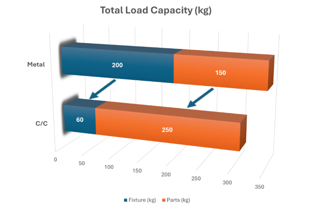
- Increased capacity: In a specific industrial application, C/C fixtures weighing 66 kg (145 lb) replaced 200 kg (440 lb) stainless-steel fixtures.
- Loading efficiency: In a furnace with a 350 kg (772 lb) total load capacity, this weight reduction allowed the “parts weight” to increase from 150 kg to 250 kg per cycle — a 66% increase in productivity.
- Productivity gains: The ratio of total fixture weight to total load capacity was reduced by 70%, enabling more components to be processed in a single cycle.
- Energy efficiency: Reducing the fixture weight lowers the total heat capacity of the load, allowing for faster heating times and a drastic reduction in the cost of energy per part.
Thermal Uniformity and Defect Reduction
Traditional metal fixtures often require supplementary “dead weights” to apply constant pressure during the brazing process. These weights, which can reach 20 kg or more, introduce significant thermal challenges:
- Thermal shadowing: Large metal weights tend to block radiant heat waves, creating “shadows” that compromise heating uniformity.
- Defect rates: Inconsistent heating leads to defective brazed parts and necessitates spacing parts further apart to ensure uniformity, which further limits productivity.
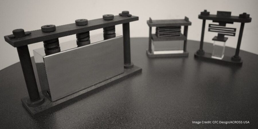
- C/C solution: The compact design of C/C fixtures, combined with lightweight springs (weighing only 70 grams), eliminates these thermal barriers. This allows for a decrease in the defect rate and an increase in total process quantity.
The Physics of C/C Spring Technology
To replace heavy dead weights, engineers utilize C/C spring technology to apply a constant load throughout the heating cycle. These springs maintain their force as temperature increases, and the brazing begins once the melting point of the filler metal is reached.
1. Continuous Fiber Coil Springs
Modern C/C coil springs are manufactured such that the long carbon fibers are spirally continuous and not segmented during the machining process. Early C/C composite coil springs were fabricated by cutting shapes out of two-dimensionally reinforced long-fiber C/C blocks. This method had a significant drawback: the reinforcing fibers were segmented during processing. Because the fibers were cut, the material could not exhibit its full structural strength, leading to a decrease in the spring constant after repeated use in high-temperature environments.
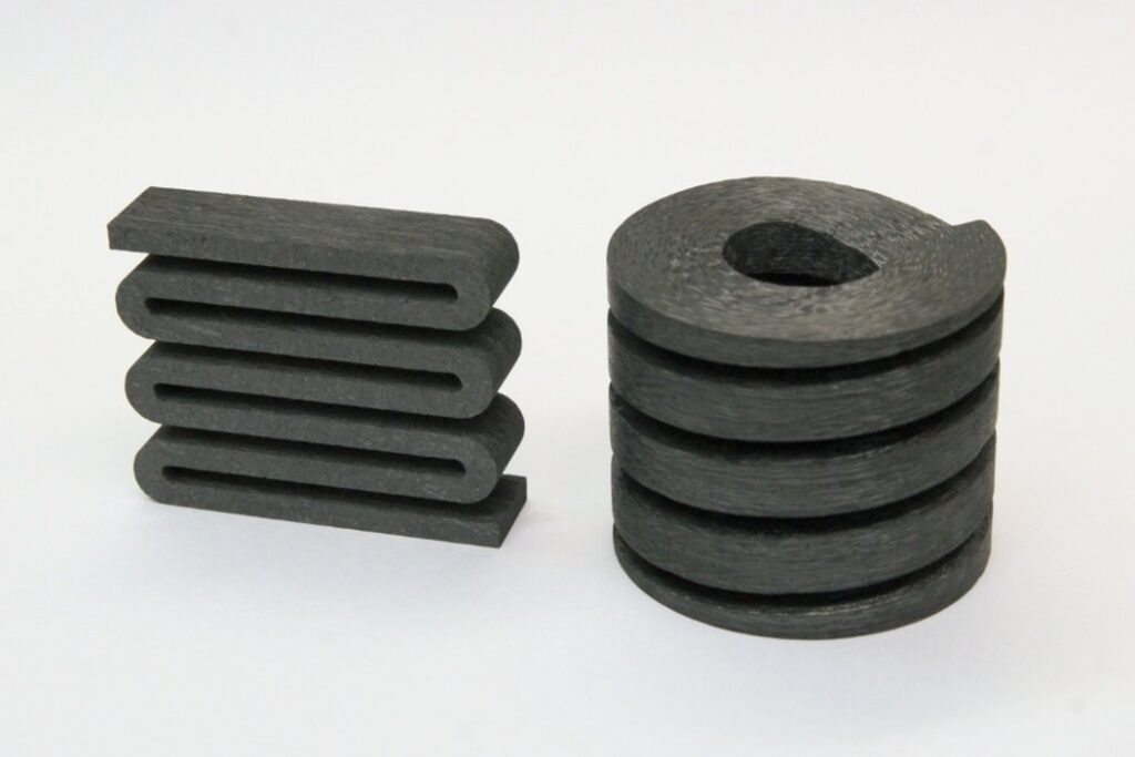
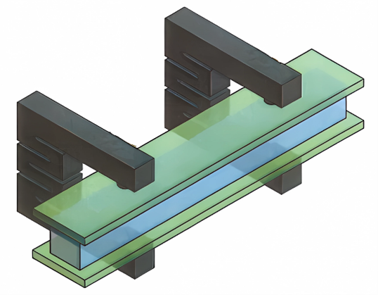
To compensate for these limitations, a proprietary spring type was developed using long carbon fibers that are spirally continuous in one direction (Figure 2). Because these fibers are not segmented, they fully demonstrate their role as a reinforcing medium, resulting in a product that maintains a stable spring constant even after repeated cycles exceeding 1000°C (1832°F).
- Durability: Because the reinforcing fibers are not cut, the spring fully demonstrates its strength and maintains a stable spring constant even after repeated use.
- Performance: A single carbon spring can generate up to 24.5 kg of force while weighing only 26–84 grams. This provides an equivalent load to metal weights that are hundreds of times heavier.
2. New Type C/C Composite Spring: “Z-Type” Spring
While continuous-fiber coil springs are highly effective, they possess inherent manufacturing disadvantages. Neatly arranging long fibers in a spiral shape is complex and difficult to scale for mass production. Furthermore, because the spring size depends on specific mold dimensions, it has historically been difficult to produce a diverse variety of spring strengths and sizes.
To address the mass-production limitations and molding size constraints of coil-shaped springs, the “Z-type” plate spring was engineered to support large loads using a more efficient manufacturing process (Figure 2). Instead of a coiled architecture, this spring is fabricated in a zig-zag, serpentine pattern using a C/C composite plate.
- Material design: The zig-zag pattern is achieved by using laminated plates where short carbon fibers are randomly oriented in a two-dimensional XY plane.
- Shear modulus: This random orientation dramatically improves the in-plane shear modulus, allowing the Z-spring to support larger loads and offer a larger deflection allowance than coil-shaped versions.
- Stability: In repeated load tests at 1250°C (2282°F), Z-type springs show a minimal 1% decrease in natural length during the first run and zero “setting” or deformation in subsequent cycles.
- Mass production: Unlike coil springs, Z-type springs can be mass produced through water-jet machining from large C/C laminate plates.
Figure 3 shows the displacement-load curve of the Z-type C/C composite spring. From this figure, satisfactory spring characteristics are exhibited, even in repeated load tests.
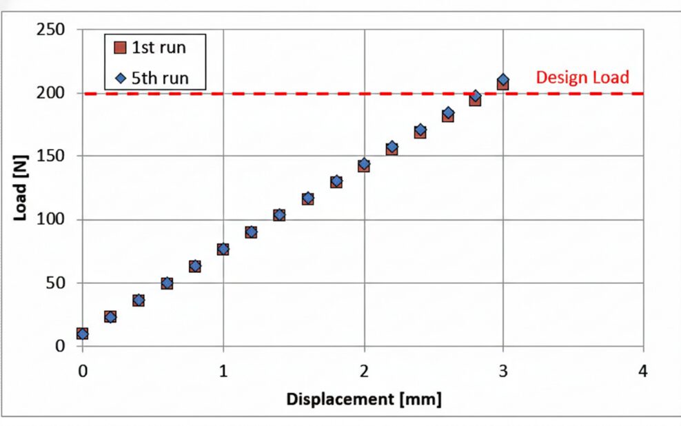
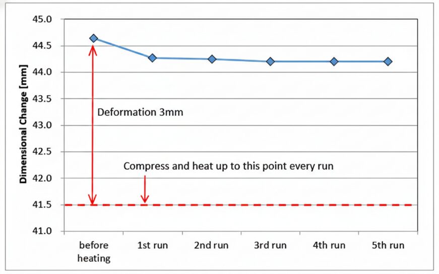
After heating the Z-type C/C composite spring in a compressed state at 1250°C (2282°F) for 30 minutes in a nitrogen atmosphere, spring characteristics were measured at room temperature and a repeated heating test was performed.
A decrease of about 1% in the natural length was observed only during the first heating run. However, the natural length did not change even if the heating was repeated after, and it was found that there was no setting at all.
Compared to coil-type C/C composite springs, C/C composite springs made from short-fiber reinforcing materials are characterized by very few shape restrictions and various configurations are achievable.
Advanced Applications: Clips, Bolts, and Large-Scale Fixtures
The versatility of C/C machining allows for specialized components that simplify complex furnace operations:
- C/C clips: Developed to simplify fixturing, these clips act as integrated springs that sandwich parts directly, eliminating the need for complicated, heavy clamp structures.
- Thermal expansion absorption: In high-temperature furnaces, graphite heaters can deform under their own weight or fail due to thermal stress at joint points. C/C bolts with a “notched” design act as integrated springs to absorb dimensional changes caused by thermal expansion, preventing damage to electrodes and joints.
- Large-scale serpentine springs: Z-springs can be manufactured in large serpentine shapes, achieving deflections of up to 22% of their natural length (e.g., a 50 mm deflection on a 230 mm spring) while maintaining satisfactory spring characteristics.
Improving Plant Economics
The transition from heavy metal fixturing to high-performance C/C composites is no longer just a technical preference but a necessity for modern plant economics. For aerospace components that demand zero-distortion and high-precision brazing, C/C fixturing provides the thermal and mechanical stability required for 21st-century manufacturing.
About The Author:
Hirotaka Nagao, Ph.D., is a technical expert at CFC Design Inc. specializing in the development of advanced carbon-fiber-reinforced carbon (C/C) composite materials. With a doctorate in material science, his research focuses on high-temperature applications and improving production efficiency through innovative C/C fixture and spring designs for furnace brazing and heat treatment environments.
For more information: Contact ACROSS USA at www.acrosscc.com.

C/C Composite Fixturing: Optimizing Precision Brazing for Aerospace Components Read More »


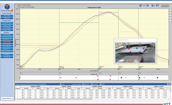
 Furnace mapping can be further developed to satisfy either CQI-9/CQI-29 or AMS2750F pyrometry standards where a two-dimensional jig is constructed to perform the temperature uniformity survey (TUS).2 Employing the plane method, a frame jig is constructed to match the furnace work zone with the necessary number of thermocouples to satisfy the furnace cross section dimensions. Temperatures recorded over the working zone are compared to the desired TUS levels to ensure that they are within tolerance as defined in the standards.
 Source: