Heat Treat Radio #105: Lunch and Learn: Batch IQ Vs. Continuous Pusher, Part 2
Have you decided to purchase batch or continuous furnace system equipment? Today's episode is part 2 of the Heat Treat Radio lunch & learn episode begun with Michael Mouilleseaux of Erie Steel. Preceding this episode were Part 1 (episode #102) and a Technical Tuesday piece, so listen to the history of these systems, equipment and processing differences, and maintenance concerns before jumping into this episode about capability and throughput.
Doug Glenn, Heat Treat Today publisher and Heat Treat Radio host; Karen Gantzer, associate publisher/editor-in-chief; and Bethany Leone, managing editor, join this Heat Treat Today lunch & learn.
Below, you can watch the video, listen to the podcast by clicking on the audio play button, or read an edited transcript.


The following transcript has been edited for your reading enjoyment.
An Example: Carburizing (00:52)
Michael Mouilleseaux: What we want to do here is just compare the same part, the same heat treating process, processed in a batch furnace and processed in a pusher.
Here we’re just going to make an example:
Pusher Load Description (00:58)

your Reader Feedback!
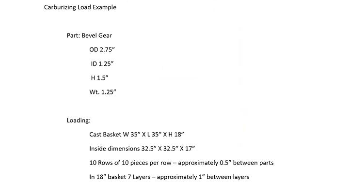
I’m going to take a fictious gear: it’s 2 ¾ inch in diameter, it’s got an inside diameter of an inch and a quarter, it’s an inch and a half tall, and it weighs 1.25 pounds. For our purposes here, we’re going to put these in a cast basket. For the furnace that we’re going to put them in, the basket size is 36 inches square — so, it’s 36 x 36. The height in this pusher furnace is going to be 24 inches; the inside dimensions of a 36-inch basket (actually it’s a 35-inch basket that sits on a 36-inch tray) is 32 ½ inches.
If I take 10 rows of parts — that’s 27 ½ inches — that gives me about a half inch between parts. That’s going to be our loading scheme. So, in one layer, it’s going to be 10 pieces of 10 rows of 10 pieces each; that gives us about a half inch between parts. It doesn’t matter why, that’s just what we’re going to do so that we have some standard to do that.
We’re going to say that this basket is 18 inches tall, so we’re going to get 7 layers of parts so that there’s approximately 1 inch between each layer of parts. This loading scheme gets us 700 pieces in a basket; it gets us 875 pounds net.
So the 36-inch basket that’s 18 inches tall and we’ve got 10 rows of 10 pieces, and we’ve got 7 layers of these things, so we have some room in between them. The reason for that is circulation of atmosphere and quenchant. This is what’s going to constitute the pusher load.
Batch Load Description (03:09)
Now, when we go to the batch load, we’re going to take four of these, because the batch furnace that we’re going to compare this to is going to be 36 inches wide and it’s going to be 72 inches long. We have two baskets on the bottom, 36, and then two of them is 72, and two on top. They’re 18 inches high, so 18 and 18 is 36 — a standard 36 x 72. It’s got 40 inches of height on it. I can take that 36 inches, put it on a 2 ½-inch tray and I can get it in and out of the furnace.
What is this four baskets? 2800 pieces in a load and 3500 pounds. That’s the difference. I’m comparing one basket, 700 pieces and 875 pounds and we’re going to compare that to what we would do if we ran a batch load, which is significantly more. It’s 2800 pieces and 3500 pounds.
What do we want to do with this?
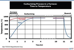
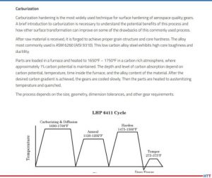
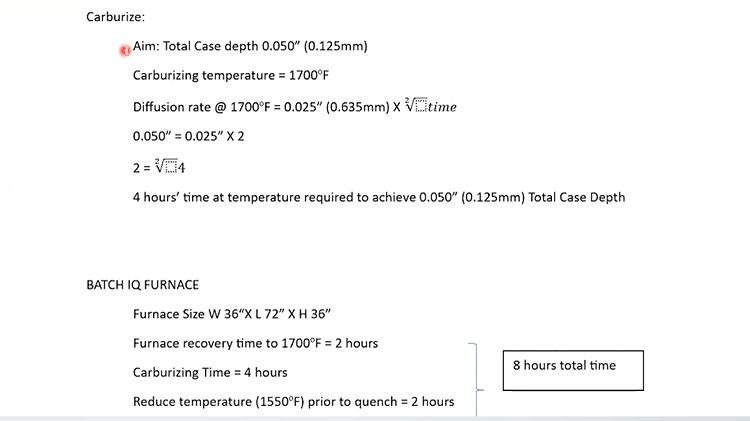
Let’s say that we’re going to carburize this, and we want 50 thousandths case (total case depth of 0/050”). Now, I will show you very soon why we’ve chosen 50 thousandths case. Because at 1700°F (which is what we’re going to carburize at), the diffusion rate is 25 thousandths of an inch times the square root of time.
Now, I can do that math in my head. 25 thousandths times 2 is 50 thousandths. That means we need four hours. So, the part would have to be in the furnace for four hours, at temperature, carburizing, in order to achieve 50 thousandths case.
Batch Furnace Time (04:59)
Let’s look at the next section. As we said, the furnace is 36 x 72 x 36 and we have 2800 pieces in the load. So, that is 1700°F. We’re going to say that there is 3500 pounds and there is probably another 800 or 900 pounds in fixturing so that’s about 4500 pounds. It’s very conservative; in a 36 x 72 furnace, you could probably get away with running 6,000 pounds. This is just a load that is well within the capability of that.
Furnace recovery is going to take two hours.
Doug Glenn: Meaning, it’s going to take you two hours to get up to temperature.
Mike Mouilleseaux: Until the entirety of the load is at 1700°F, that’s right. Inside, outside, top to bottom.
We’re going to carburize this at four hours, as we described previously; we calculated that and we need four hours to get our 50 thousandths case. Then we’re going to reduce the temperature in the furnace to 1550°F so that we can quench it.
So, we have two hours of furnace recovery, four hours at carburizing, two hours to reduce the temperature and attain a uniform 1550°F. That’s eight hours, and that’s what you would term an 8-hour furnace cycle.
We know that we have 2800 pieces in the load. In eight hours (2800 divided by 8) you’ve got 350 pieces/hour. That’s what the hourly productivity would be in this load.
We won’t talk about “what could we do.” There’s a lot of things that we could do. This is simply an example.
Pusher Furnace Time (07:05)
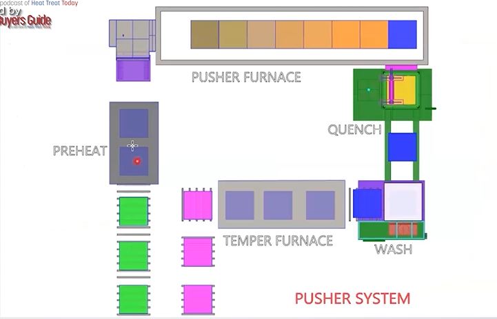
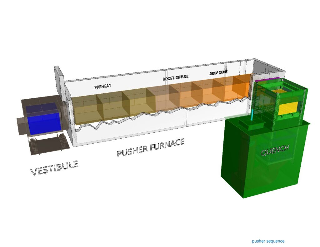
Now, in the pusher load, as previously described, it’s 36 x 36 and it’s 24 inches high. Now, we know that we have a basket that’s 18 inches high. Again, it’s going to sit on a 2-inch tray, so we’ve got 21 inches of the top of the basket that is going to fit in the furnace; there are going to be no issues with that whatsoever.
When we looked at the first description of that furnace, there were two positions in recovery, there were four positions to boost to diffuse, and there were two positions to reduce the temperature.
The controlling factor is that we want four hours at temperature. In the boost and diffuse, we have four positions. The furnace cycles once per hour.
We get one load size (700 pieces, 875 pounds) every hour. So, in this example (an 8-position, 36-square pusher) this process would yield 700 pieces an hour, and a batch furnace loaded as we described (same exact loading and number of pieces/basket) would yield 350 pieces/hour. In this scenario, the pusher furnace is going to produce twice the number of parts/hour that the batch would.
So, you would say, “Well, let’s just do that.” What you have to understand is that every hour, you are going to produce 700 pieces. If we went back and we looked at that description of what that pusher system looked like, you would see there are 23 positions in that. When I load a load, it’s going to be 23 hours before the first load comes out.
What we’re talking about is whether or not there were 700 pieces and 800 pounds, 23 of those[ET10] [BL11] load.
The point would be, you either have to have enough of the same product or enough of similar product that can be processed to the same process to justify using something like this. Because if we want to change the cycle in the furnace. So, can we do that? The answer is absolutely, yes.
The preheat there, that stays at relatively the same temperature. The first zone in the furnace where we’re preheating the load, that temperature can be changed, as can the temperature in the boost diffuse and/or cycle time.
So, in our example, we used an hour. What if you wanted 40 thousandths case and you’re going to be closer to 45 minutes or 50 minutes of time, how would you accomplish that? That can be done.
Typically, commercial heat treaters would come up with a strategy on how to cycle parts in and hold the furnace, or how many empties you would put in the furnace before you would change the furnace cycle.
Obviously, in the last two positions, where you’re reducing temperature, you could change the temperature in either the first two positions, where you’re preheating the load, or you could change the carburizing temperature, because when we’re dropping the temperature, it doesn’t have a material effect upon that.
Typically, in an in-house operation, you would not do that kind of thing, for a couple of reasons, not the least of which would be considering the type of people that you have operating these furnaces. They come in and out from other departments, and this is the kind of thing that you would want someone experientially understanding the instructions that you’ve given them. The furnace operator is not necessarily going to be the one to do it; this may be a pre-established methodology. You want them to execute that. But if you have somebody that is running a grinder and then they’re running a plating line and then they’re coming and working in the heat treat, that would not be the recipe for trying to make these kinds of changes.
As I described to you before, I worked in another life where we had 15 pushers. They were multiple-row pushers. We made 10,000 transfer cases a day. The furnace cycle on every furnace was established on the 1st of January, and on the 31st of December it was still running the same furnace cycle. You never changed what you were doing. The same parts went into the same furnaces and that’s how they were able to achieve the uniform results they were looking for.
Pusher Furnaces and Flexibility (12:45)
So, the longer the pusher furnace is, the less flexible it is.
In this example, you have eight. You know, there are pusher furnaces that have four positions. If you think about it, in a 4-position furnace, you could empty it out pretty quickly and change the cycle.
There are a lot of 6-position pusher furnaces in the commercial heat treating industry; that seems to be a good balance. The number of multiple-row pushers in the commercial industry, they’re fewer and far between. I’m not going to say they’re nonexistent, but enough of the same kind of product to justify that is difficult.
Distortion, Quenching, and Furnace Choice (14:28)
I think the bottom line here is, for companies that are having high variability, low quantity, low volume loads, generally speaking, your batch is going to be good because it’s very flexible, you can change quickly.
However, with a company like the one you were describing where there is low variability and very high volume, pushers are obviously going to make sense. But there is a whole spectrum in between there where you’re going to have to figure out which one makes more sense — whether you’re going to go with a batch or a continuous.
Mike Mouilleseaux: Possibly underappreciated is the aspect of distortion.
In that carburizing example, you’d say, “We have an alloy steel, we’re aiming for 50 thousandths case — what’s the variation within a load?” And I’m going to say that it is going to be less than 5 thousandths, less than 10%. From the top to the bottom, the inside to the outside, it’s going to be less than 5 thousandths. That same process, in the pusher furnace is going to be less than 3 thousandths.
That’s one aspect of the metallurgy. The other aspect is quenching.
Doug Glenn: 5 thousandths versus 3 thousandths — 3 thousandths is much more uniform, right?
Mike Mouilleseaux: Correct.
Doug Glenn: And that’s good because that way the entire load is more consistent (in the continuous unit, let’s say).
Mike Mouilleseaux: That is correct.
Then there is the consistency in quenching. In the batch furnace, you’re quenching 36 inches of the parts. If we had seven layers in the pusher, we have 14 layers of parts in the batch. What are the dynamics involved in that?
We have experience that the ID of a gear (it’s a splined gear) in a batch furnace, we were able to maintain less than 50 microns of distortion. There is a lot involved in that, that’s not for free; there’s a fair amount involved in that and it’s a sophisticated cycle, if you will. That same cycle in a pusher furnace, same case depth, similar quenching strategy, will give you less than half that amount of distortion.
To the heat treater, where we’re talking about the metallurgy of this, you’re going to think 5 thousandths or 3 thousandths is not a big deal.
To the end-user, that reduction in distortion all of a sudden starts paying a number of benefits. The amount of hard finishing that has to be done or honing or hard broaching or something of that nature suddenly becomes far more important.
Doug Glenn: Yes. That adds a lot of money to the total process, if you’ve got to do any of those post heat treat processes.
Mike Mouilleseaux: To a large extent, that is due to the fact that you have a smaller load. If you have a smaller load, you have less opportunity for variation — it’s not that it’s all of a sudden magic.
Doug Glenn: And for the people that don’t understand exactly what that means, think about a single basket that goes into a quench tank and four baskets, arranged two on top and two on bottom. The parts in the middle of that are going to be quenched more slowly because the quench is not hitting it as much.
So, the cooling rates on a stacked load are going to be substantially different than for a single basket, and that’s where distortion can happen.
Mike Mouilleseaux: There are a tremendous number of components that are running batch furnaces successfully. The transportation industry, medical, aerospace, military — are all examples. I’m simply pointing out the fact that there is an opportunity to do something but what we have to keep in mind is — how many of those somethings are there available?
The one thing you would not want to do is try to run four loads in a pusher furnace that could hold 10 because the conditions are not going to be consistent. The front end (the first load) has nothing in front of it so it’s heating at a different rate than the loads in the center, and the last load is cooling at a different rate than the loads that were in the center. That which I just described to you about the potential improvement in distortion, that would be negated in that circumstance.
Doug Glenn: If you’re running a continuous system at full bore and you’re running a batch system at full capacity, especially when you get to the quench, there are a lot of other variables you need to consider in the batch.
This is simply because of the load configuration, and the rates of cooling from the outer parts — top, bottom, sides, as opposed to the ones in the middle. Whereas with a single basket, you still have to worry about the parts on the outside as they’re going to cool quicker than the parts on the inside, but it’s less so, by a significant degree.
Mike Mouilleseaux: Something that I have learned — which is totally counterintuitive to everything that I was educated with and everything that I was ever told— we’d always thought that it was the parts in the top of the load where the oil had gone through and had an opportunity to vaporize and you weren’t getting the same uniform quench—those were the parts that you had the highest distortion.
Counterintuitively, it’s the parts in the bottom of the load that have the greatest degree of distortion. It has very little to do with vaporizing the oil and it has everything to do with laminar flow versus turbulent flow.
Doug Glenn: In the quench tank, is the oil being circulated up through the load?
Mike Mouilleseaux: Yes.
Doug Glenn: So, supposedly, the coolest oil is hitting the bottom first.
Mike Mouilleseaux: Yes.
Thoughts on the Future of Furnace Improvement (22:20)
Doug Glenn: What about the future on these things?
Mike Mouilleseaux: Where do we think this thing is going? Obviously, you’re going to continue to see incremental improvement in furnace hardware: in burners, in controllers, in insulation, in alloys. These things will be more robust; they’re going to last longer. If we looked at a furnace today and we looked at a furnace that was made 50 years ago, and we stood back a hundred yards, almost no one could tell what the difference was, and yet, it would perform demonstrably different. They are far more precise and accurate than ever.
For the process control systems, we’re going to see real-time analysis of process parameters. We don’t have that now. I think that machine learning is going to come into play, to optimize and predict issues and prevent catastrophic things.
Heating rates that we talked about: Why are we not going to see machine learning or AI finding the problem sooner, rather than my looking at it and seeing it a week later and thinking, “You know, it looks like these things are starting to take longer to heat up.” Why can’t that be noticed by some kind of machine learning or something like that?
In terms of atmosphere usage, if you’re running the same load, and you run it a number of times, the heating rate should be the same, and the amount of gas that you use to carburize that load should be exactly the same. But if you have a problem with atmosphere integrity — you got a door leak, you got a fan leak, or you got a water leak on a bearing — those things are going to change. Now, by the time it gets your attention, you could’ve dealt with that much sooner and prevented other things from happening.
"For the process control systems, we’re going to see real-time analysis of process parameters. We don’t have that now. I think that machine learning is going to come into play, to optimize and predict issues and prevent catastrophic things."
So, did it cause a problem with the part? By the time it causes a problem with the part, it’s really serious. The point is that there is something between when it initiated and when it’s really serious. With the right kind of analysis, that could be prevented. I think that that kind of thing is coming.
Motor outputs, transfer times — I see all of those things being incorporated into a very comprehensive system whereby you’re going to understand what’s happening with the process in real-time. If you make adjustments, you’re going to know why. Then you’re going to know where you need to go and look to fix it.
And last but not least, the integration of the metallurgical results in the process. Before you have a significant difference in case depth or core hardness. There are reasons that these things happen. Again, this machine learning, expert analysis, AI (whatever it is we’re going to call that) we’re going to see that that’s going to do it, and we’re not relying on somebody to figure why it’s happening.
The other thing I see happening in the future is all about energy and greenhouse gases. Our Department of Energy has an industrial decarbonization roadmap today, and it’s being implemented, and we don’t even know it. One of the targets in this industrial decarburization roadmap is reduction in greenhouse gases: 85% by 2035, net zero by 2050.
So, what does that mean? I’ve listened to the symposiums that they have put on. There are three things that they’re looking for and one is energy efficiency. I’m going to say that we’ve been down that road and we’ve beat that dog already. Are there going to be other opportunities? Sure. It’s these incremental things, like burner efficiency. But there is no low hanging fruit in energy efficiency.
The other thing is going to be innovative use of hydrogen instead of natural gas because the CO₂ footprint of hydrogen is much lower than that of natural gas. If you look at how the majority of hydrogen is generated today, it’s generated from natural gas. How do you strip hydrogen out of there? You heat it up with natural gas or you heat it up with electricity. Hydrogen is four times the cost of natural gas as a heating source.
The other thing that they’re talking about is electrifying. It’s electrify, electrify, electrify. The electricity has to be generated by clean energy. So, does that mean that we run our furnaces when the wind is blowing or the sun is out, or we’re using peaker plants that are run off hydrogen, and the hydrogen is generated when the sun is shining or the wind is blowing, and we’re stripping out the natural gas?
From what I, personally, have seen with these things, these are absolutely noble goals. You could not disagree with them whatsoever. The way that they want to go about accomplishing it, and the timeline that they wish to accomplish that in, is unrealistic.
If you look at how the majority of hydrogen is generated today, it’s generated from natural gas. How do you strip hydrogen out of there? You heat it up with natural gas or you heat it up with electricity. Hydrogen is four times the cost of natural gas as a heating source.
Doug Glenn: Well, Michael, don’t even get me going on this! There are a lot of different things that are going on here but it’s good to hear you say this stuff. I agree with you on a lot of this stuff. They are noble goals; there is absolutely nothing wrong with electrifying.
Now, I do know some people — and even I would probably fall into the camp of one of those guys — that questions the premise behind the whole decarbonization movement. I mean, is CO₂ really not our friend? There’s that whole question. But, even if you grant that, I agree with you that the timeframe in which they’re wanting to do some of these things is, I think, fairly unrealistic.
It’s always good to know the reality of the world, whether you agree with it or not. It’s there, it’s happening, so you’ve got to go in with eyes wide open.
Safety Concerns (29:41)
Mike Mouilleseaux: The safety concerns on these are all very similar. You know, the MTI (Metal Treating Institute) has some pretty good safety courses on these things, and I think there are a lot of people who have taken advantage of that. The fact that it’s been formalized is much better.
When I grew up in this, it was something that you learned empirically, and making a mistake in learning it, although the learning situation is embedded in you, sometimes the cost of that is just too great, so that the probability of being hurt or burnt or causing damage to a facility, is just too great.
There are definitely things that need to be addressed with that, and there are some very basic things that need to be done.
Doug Glenn: Michael, thanks a lot. I appreciate your expertise in all these areas, you are a wealth of knowledge.
Mike Mouilleseaux: My pleasure. It’s been fun.
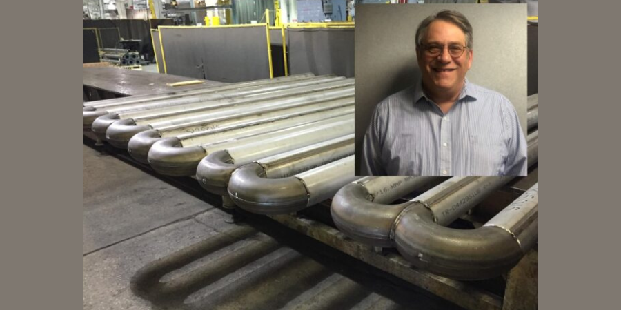
About the Expert:
Michael Mouilleseaux is general manager at Erie Steel LTD. Mike has been at Erie Steel in Toledo, OH since 2006 with previous metallurgical experience at New Process Gear in Syracuse, NY and as the Director of Technology in Marketing at FPM Heat Treating LLC in Elk Grove, IL. Having graduated from the University of Michigan with a degree in Metallurgical Engineering, Mike has proved his expertise in the field of heat treat, co-presenting at the 2019 Heat Treat show and currently serving on the Board of Trustees at the Metal Treating Institute.
Contact: mmouilleseaux@erie.com
Search heat treat equipment and service providers on Heat Treat Buyers Guide.com
Heat Treat Radio #105: Lunch and Learn: Batch IQ Vs. Continuous Pusher, Part 2 Read More »