Welcome to another Technical Tuesday for 18 hard-hitting resources to use at your heat treat shop. These include quick tables, data sets, and videos/downloadable reports covering a range of heat treat topics from case hardening and thermocouples to HIPing and powder metallurgy.
Defining Terms: Tables and Lists
Table #3 Suggested Tests and Frequencies for a Polymer Quench Solution (in article here)
Case Hardening Process Equipment Considerations (bottom of the article here)
Two simulations of a moving billet through heating systems (in article here)
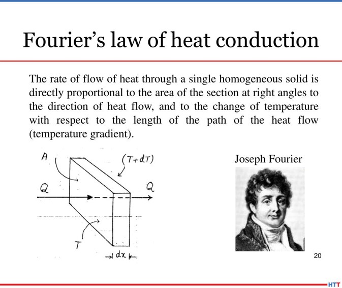
Fourier’s Law of Heat Conduction (in article here)
Webinar on Parts Washing (link to full webinar at the top of the review article here)
Materials 101 Series from Mega Mechatronics, Part 4, Heat Treatment/Hardening here
Heat Treat TV: Press-and-Sinter Powder Metallurgy here
BONUS: 39 Top Heat Treat Resources
Heat Treat Today is always on the hunt for cutting-edge heat treat technology, trends, and resources that will help our audience become better informed. To find the top resources being used in the industry, we asked your colleagues. Discover their go-to resources that help them to hone their skills in the 39 Top Heat Treat Resources on this page of the September print magazine.
With "advances in electric vehicle transportation, semiconductor fabrication, novel material development, and miniaturization, the ‘performance envelope’ continues to broaden." This requires revisiting some tried and true heat treating techniques and their applications.
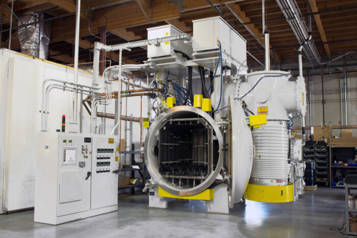
Read on to see what Tom Palamides, senior sales and product manager at PVA TePla America, Inc., has to say about how diffusion bonding may replace brazing for certain applications. Check out other Heat Treat Todayoriginal content or Technical Tuesday articles in the search bar to the right.
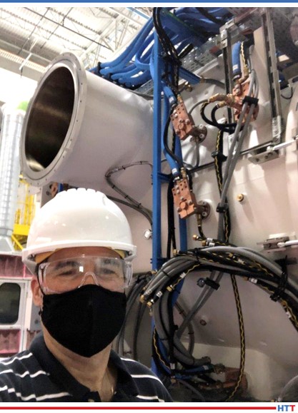
Tom Palamides with diffusion bonding furnace Source: PVA TePla
As we begin to see the light at the end of the tunnel from the devastating economic shock of the COVID pandemic, engineering companies, heat treaters, and material process engineers must work in unison to adopt refined manufacturing processes to meet the demands of critical component design. Harnessing new tools and techniques allows for real operational enhancements and is an increasing trend across many industries.
Brazing historically has been, and remains, the stalwart technique for joining precision-machined components. However, with advances in electric vehicle transportation, semiconductor fabrication, novel material development, and miniaturization, the “performance envelope” continues to broaden. Two of the most common limitations of brazing are that it is challenging to prevent alloy flow in small diameter micro-channels. When such a part is used in higher temperature operating conditions, the joint can introduce elemental cross-contaminants for ultraclean environments. To this end, diffusion bonding, which uses pressure and relatively low heat (about 50%-90% of the absolute melting point of the parent material) to join similar, or dissimilar materials, holds promise.
If one examines the aerospace, semiconductors, energy, medical devices, and electronic component markets, new and higher performance demands have become the norm. Next-generation product designers are, therefore, evaluating new bonding processes to achieve improved performance goals. Many now view diffusion bonding as the “next leap” for metallic materials processing; it offers several unique advantages for complex geometric structures and materials that can operate under strenuous high-performance conditions.
Solid-state diffusion bonding results from the controlled combination of three (3) key processing parameters: pressure, temperature, and cycle time. The careful balancing of these three parameters promotes bonding at the joining surfaces. The result is a virtually invisible uniform interface, devoid of metallurgical discontinuities and porosity.
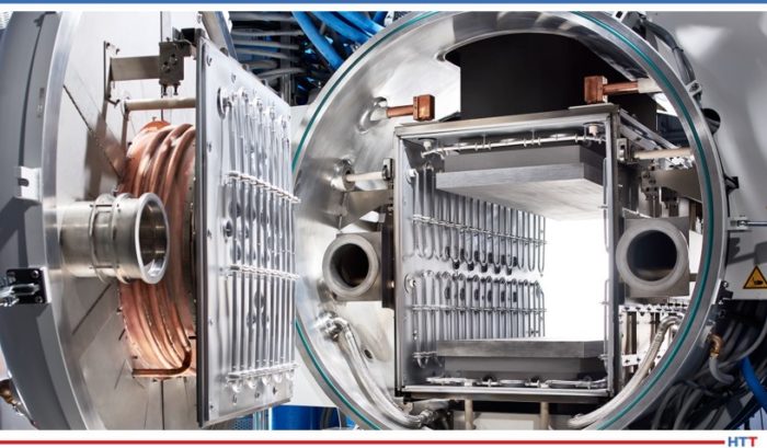
PVA TePla’s commercial diffusion bonding furnace for joining similar and dissimilar materials Source: PVA TePla
Process engineers have evaluated solid-state diffusion bonding at a research-level for more than fifty years; however, much has changed recently. Building on twenty-five years of successful commercial product solutions, such as aircraft disk brakes and specialized heat exchangers, diffusion bonding is now an “upgraded” process. With advancement in the use of high-strength carbon matrix composites and advanced furnace designs that leverage sophisticated electronics and hydraulic systems controllable to within thousandth-of-an-inch, commercial interest now extends far beyond aerospace and energy.
The most sophisticated global companies in electronic instrumentation and semiconductors view diffusion bonding as the wave of the future. The functional-value that 21st-century diffusion bonding technology now offers is a unique-and-beneficial solution in a class by itself; designers came to this realization after being confronted with component performance issues that could not be resolved by traditional brazing. Materials currently under consideration include pure aluminum, aluminum alloys, stainless steels, and nickel-based alloys as well as any other material, such as coated substrates for power electronics or glass and special material combinations (dissimilar joints).
Today is an exciting time for any engineer who wants to upgrade or produce new and/or higher performance designs, and heat treaters need to be aware of a new process emerging in their midst. It is essential for the heat treater to know the various types of capital equipment and the performance specifications that have and are evolving with the diffusion bonding process. Companies are learning to operate with smarter devices and more intelligent methods. Why not evaluate diffusion bonding to improve productivity, product quality, and material performance for your next-generation products?
About the Author: Thomas Palamides, senior sales and product manager at PVA TePla America, Inc., has a background in materials science and international marketing. He holds two U.S. patents. He is passionate about facilitating a broader understanding of how material processes fundamentally influence design and manufacturing cost, as well as how they improve business.
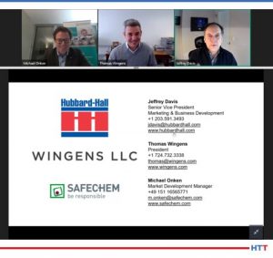
In January 2021, Hubbard-Hall hosted a free webinar with Thomas Wingens of Wingens International and Michael Onken of SAFECHEM. These two experts described the influencing factors for technical cleanliness and some solutions for washing. This Technical Tuesday, we are sharing an Original Content overview of what happened at the virtual event.
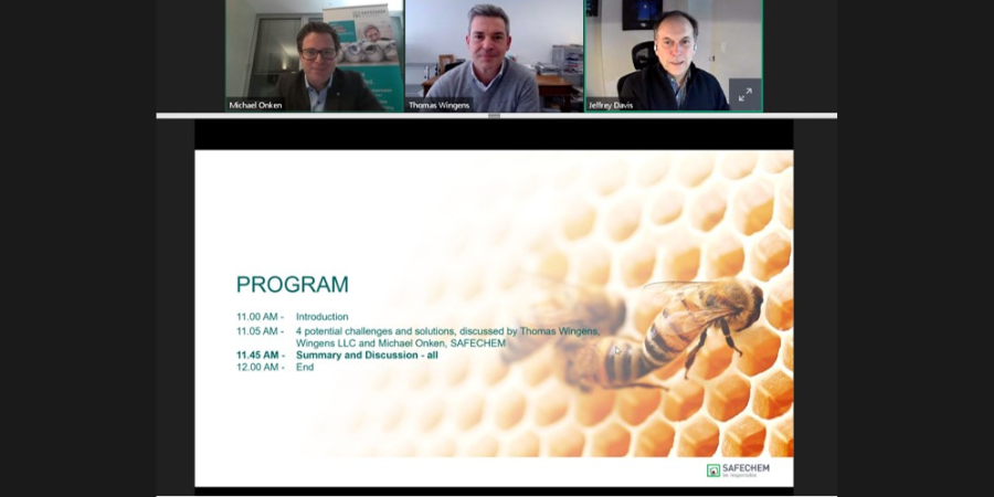
This year, we are seeing a lot of online-adapted education for the heat treat industry. One of these webinars was "Solving The 4 Most Common Metal Cleaning Challenges In Heat Treatment" hosted for free by Hubbard-Hall. Jeff Davis, SVP of business development and distribution at the chemical supplier, introduced experts Thomas Wingens, longtime metallurgist with a lifetime of exposure in the heat treating industry, and Michael Onken, market development manager at SAFECHEM. Here is a brief rundown of what they talked about.
The concluding slide from Hubbard-Hall's webinar, Tuesday February 2, 2021. Source: Screen shot from Hubbard-Hall Webinar February 9, 2021
How Do You Clean | Why Do You Clean | Who Cleans
The audience indicated that if they cleaned, they overwhelming used water-based cleaners on their products.
The experts then gave four clear reasons why heat treaters should clean:
Optics -- get rid of stains
Achieve Uniformity -- resolve soft spots and stop-off paint issues
Brazing Voids -- prevent the appearance of bubbles on your part
Contamination of the Furnace -- all furnaces, even vacuum furnaces, are susceptible to contamination
Smoking Parts -- if not cleaned well, left-over oil on a part can smoke up
With all of these reasons and with the specificity of the part, all heat treaters should pay attention to how they clean their products, but especially commercial heat treaters. The reason? Commercial heat treaters are in the most challenging situation with cooling fluid contamination, corrosion protection, chips, dirt, and dust as they treat a variety of different parts at their facility. As a note, the experts noted that commercial heat treaters could remove these contaminants with sandblasting, pickling, and sputtering.
4 Challenges - 4 Solutions
One by one, Wingens shared a cleaning challenge that Onken immediately responded to.
1 - Residual Contamination Results in Insufficient Hardening (T.W.)
Residual contamination may be because the cleaning method you are using is insufficient or non-existent. Still, Wingens noted there is clear evidence that insufficient cleaning for nitriding and ferritic nitro caburizing (FNC) leads to white spots. This, among other things, is a cause for concern and may compromise the part quality.
1 - Consider Cleaning Factors, Regulations, and Requirements (M.O.)
If you are running into this cleaning challenge, you have to first consider specific factors, regulations, and requirements for implementing optimal cleaning, says Onken.
Time. You want cleaning to be as short as possible because "time is money."
Temperature.
Mechanics of the cleaning machine.
Chemistry of the Cleaning Agents. Alkaline, neutral, or and organic solvents? You must know what type of contaminations you have on the surface -- if it's polar or non-polar -- in order to use the correct solvent in cleaning the part.
Are the contaminants fat, resins, oil, petroleum or salts, emulsions, emulsions?
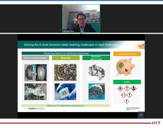
Additionally, there are several factors of the part itself, pricing, and Environmental Health & Safety standards that do come into play, as Onken lists in the slide below.
Michael Onken sharing factors influencing technical cleanliness. Source: Screen shot from Hubbard-Hall Webinar February 9, 2021
2 - Surface Stains on Finished Product (T.W.)
This is a pretty straight forward challenge: you don't want the surface stain, so what do you do?
2 - Type of Contamination: Polarity (M.O.)
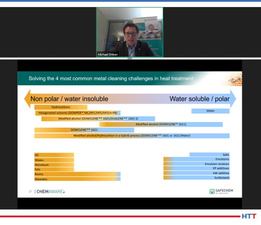
First, you want to clean "like-with-like." That is, if you have a water insoluble/non-polar contaminant like petroleum or wax, you want to clean with an insoluble/non-polar cleaner like halogenated solvents. Likewise, if the contaminants are water soluble/polar like salts or emulsion residues, then you clean with water-based cleaners. Check out the chart below that Onken shared at the webinar to see how specific cleaners are non-polar, polar, or even hybrid.
Polarity of cleaners and contaminants presented by Michael Onken at SAFECHEM. Source: Screen shot from Hubbard-Hall Webinar February 9, 2021
Additionally, the way your load is situated can influence what cleaner you use. For a basket load, you'll want to use a cleaner with low surface tension like solvents since those can penetrate and move through the complex geometry of the load.
3 - Inconsistent Cleaning (T.W.)
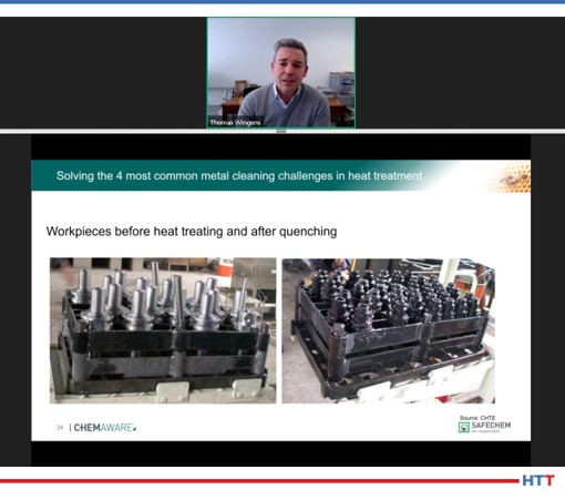
The impact of a cleaner decreases in strength over time, particularly with solvents, leading to an oily surface. (See the example below.) What to do?
Oily parts before hat treating and after quenching. Source: Screen shot from Hubbard-Hall Webinar February 9, 2021
3 - Process Stability (M.O.)
There are preventative measures, Onken highlights, that emphasizes process stability that can handle high through-put that will clean all of the parts you have uniformly:
Solvents: These are 100% composed of solvent with a stabilizer. Monitor build up of acids only, not the concentration of cleaner itself.
Water cleaner: These are 90-99% water mixed with other chemical(s). Therefore, they are much more complex. Check out alkalinity.
Bottom line: keep an eye on how your cleaners are doing so that you always know their quality before you use them.
4 - The Cost. (T.W.)
Wingens pointed out that it is costly to invest in a cleaner, and so how is a heat treater to mitigate this practical challenge?
4 - Efficient Product Use (M.O.)
First, look at efficiency of aqueous cleaning. Solvent cleaning is now in closed machines, not open machines. It is simply not that efficient to use an open machine because a lot of the cleaner disperses into the atmosphere when it is in use. That is why it is more common to see closed cleaning process. Vacuum Tight Machines close the processes even more.
Do what can to conserve material and keep the process efficient and effective.
Final Comments
The experts left the live webinar with a few final comments, noting that there is a move away from water-based cleaning because of the constraints of being able to do batch part cleaning (see solution #2). Additionally, they reiterated that investment costs are higher for closed system with a vacuum; but due to their efficiency, that investment can be paid-off fairly quickly.
If you are interested in catching the next webinar, "Do You Know Your Real Cost of Cleaning?" is happening next week, February 23, 2021 at 2:00pm ET. Again, the recorded webinar can be accessed here.
All images were captured during the live webinar on February 2, 2021.
How does this heat treat equipment supplier help a fishhook heat treater with their brazing and induction needs? Find out in today’s Best of the Web featured case study from Ambrell Induction Heating Solutions.
The client needed to heat two pairs of fishhooks within a steel tube to form an anchor. This brief case study demonstrates the value in testing new methods to optimize heat treating results.
An excerpt:
[blockquote author=”Bret Daly, The Ambrell Blog” style=”1″]It took 35 seconds or less to heat each sample to temperature. For one of the samples, to prevent overheating of the tube, braze wire was cut up and put inside the tube along with the fishhooks. That way, the entire assembly would…[/blockquote]
One of the great benefits of a community of heat treaters is the opportunity to challenge old habits and look at new ways of doing things. Heat TreatToday’s101 Heat TreatTipsis another opportunity to learn the tips, tricks, and hacks from some of the industry’s foremost experts.
Heat TreatToday’s latest round of 101 Heat Treat Tips is featured in Heat TreatTodayfall issue (also featuring the popular 40 Under 40).
Today’s selection includes tips from ECM USA, Carrasco Hornos, and Quaker Houghton. Each of them has provided quick steps or comments on a variety of topics ranging from furnace brazing to furnace expenses to quench performance or maintenance.
Heat TreatTip #1
How to Achieve a Good Braze
In vacuum brazing, be certain the faying surfaces are clean, close and parallel. This ensures the capillary action needed for a good braze.
A good brazing filler metal should:
1. Be able to wet and make a strong bond on the base metal on which it’s to be applied.
2. Have suitable melt and flow capabilities to permit the necessary capillary action.
3. Have a well-blended stable chemistry, with minimal separation in the liquid state.
4. Produce a good braze joint to meet the strength and corrosion requirements.
5. Depending on the requirements, be able to produce or avoid base metal filler metal interactions.
(ECM USA)
Heat TreatTip #2
How Much Lost Money Flows Through the Walls of Your Furnace
In a strict sense, heat flows through the insulating lining of your furnace wall: the lower the outside temperature in the furnace shell, the less heat is lost and, consequently, less money.
Fourier’s Law of Heaat Conduction (Source: Carrasco Hornos)
For example, an outside temperature on the oven shell of 160°F (71°C) equals a heat loss of approximately 190 BTU/hr ft2, just multiply this number by the square footage of the entire outside surface of the oven. A well-designed and well-maintained insulation can reduce the outside temperature of the shell, say 120°F (49°C), and heat losses would be close to 100 BTU/hr ft2, that’s 90% more heat lost and therefore fuel.
So, my Tip for today is: “Let’s go for the basics that don’t change, and it will always give good results.” By the way, how many furnaces are there in your plant and how many square feet do their surfaces add up to?
(Carrasco Hornos)
Heat TreatTip #4
Check Your Quench Oil
Safety – Performance – Oxidation
Safety
Water content should not exceed a maximum of 0.1% in the quench oil.
Flash point should be checked to ensure no extraneous contamination of a low flash point material (i.e. kerosene) has been introduced into the quench tank.
Performance
Cooling curve analysis or GM Quenchometer Speed should be checked to confirm the quench oil is maintaining its heat extraction capabilities. Variances in heat extraction capabilities could possibly lead to insufficient metallurgical properties.
Oxidation
TAN (total acid number) and Precipitation Number should be checked to ensure the quench oil is thermally and oxidatively stable. Oxidation of the quench oil can lead to staining of parts and possible changes in the heat extraction capabilities.
Sludge content should be checked… filter, filter, filter… sludge at the bottom of the quench tank can act a precursors for premature oxidation of the quench oil.
Work with your quench oil supplier on a proactive maintenance program… keep it cool… keep it clean… keep it free of contamination to extend the life of your quench oil.
(Quaker Houghton)
Heat TreatTip #28
Aqueous Quenchant Selection Tips
Greenlight Unit (Source: Quaker Houghton)
Determine your quench: Induction or Immersion? Different aqueous quenchants will provide either faster or slower cooling depending upon induction or immersion quenching applications. It is important to select the proper quenchant to meet required metallurgical properties for the application.
Part material: Chemistry and hardenability are important for the critical cooling rate for the application.
Part material: Minimum and maximum section thickness is required to select the proper aqueous quenchant and concentration.
Select the correct aqueous quenchant for the application as there are different chemistries. Choosing the correct aqueous quenchant will provide the required metallurgical properties.
Review selected aqueous quenchant for physical characteristics and cooling curve data at respective concentrations.
Filtration is important for aqueous quenchants to keep the solution as clean as possible.
Check concentration of aqueous quenchant via kinematic viscosity, refractometer, or Greenlight Unit. [See image: Hougton Intn’l Greenlight Unit and/or Houghton Int’l GL Display B] Concentration should be monitored on a regular basis to ensure the quenchant’s heat extraction capabilities.
Check for contamination (hydraulic oil, etc) which can have an adverse effect on the products cooling curves and possibly affect metallurgical properties.
Check pH to ensure proper corrosion protection on parts and equipment.
Check microbiologicals which can foul the aqueous quenchant causing unpleasant odors in the quench tank and working environment. If necessary utilize a biostable aqueous quenchant.
Implement a proactive maintenance program from your supplier.
Jim Grann, Technical Director, Ipsen (photo source: www.ipsenharold.com)
We all like to make savvy commercial decisions, in fact, Heat Treat Today’s 101 Heat Treat Tips on page 20 of this digital magazine is a great example of tips that can save you time and money. But will it pay off to use your conventional vacuum furnace for aluminum brazing?
Questions involving safety, effectiveness, and quality might come to mind with this proposal. Before implementing such a strategy, head over to Heat Treat Today’s best of the web Technical Tuesday article by Jim Grann, technical director at Ipsen. He tackles the components of aluminum brazing versus the capabilities of conventional vacuum furnace as well as detailing some of risks that can happen if you do try to use your conventional vacuum furnace for aluminum brazing.
An excerpt: “By nature, vapor pressure aids in the depletion of magnesium and parent aluminum alloys in high vacuum, depositing magnesium onto the hot zone and into the shielding… Proper vacuum aluminum brazing requires special components that standard vacuum furnaces generally do not have, including…”
Dr. Steve Offley, Product Market Manager, PhoenixTM
Knowing the precise temperature from within your continuous heat treat process is now possible. In this Heat Treat Today Technical Tuesday article, Steve Offley, “Dr. O,” Product Marketing Manager at PhoenixTM identifies how this innovative temperature profiling system can help you with your continuous aluminum brazing or other processes.
This article appeared in the edition June 2020 edition of Heat Treat Today’sAutomotive Heat Treating magazine.
In the automotive industry, aluminium brazing is key to many of the manufacturing processes used to produce radiators, condensers, evaporators, etc. The quality of the brazing process is important to the performance and product life for its intended function. A critical requirement of the brazing process is the optimization and control of the product temperatures during the complete brazing process. A valuable tool to achieve such requirements is the use of ‘Thru-process’ temperature profiling as a direct alternative to the traditional trailing thermocouples as discussed in the following article. Obtaining the product temperature profile through the brazing furnace gives you a picture of the product/process DNA.
The Basic Brazing Principle and its Temperature Dependence
Aluminium brazing employs the principle of joining aluminium metal parts by means of a thinly clad soldering ‘filler’ alloy, whose melting point is lower than the base/parent metal.
As part of the brazing process, control of the product temperature is critical to achieve selective melting of the filler alloy 1076°F-1148°F (580°C -620°C) to allow it to flow and fill the joints between the parent metal substrate without risk of melting the substrate itself. Often the difference between the melting points of the two materials is small, so accurate temperature monitoring through the entire furnace is critical to the success of the brazing process.
[spacer color="3366ff" icon="fa-lightbulb-o"]
PhoenixTM works with major automotive radiator manufacturer customizing a brazing barrier solution to meet their specific application needs.
PhoenixTM was approached by a major automotive radiator manufacturer in the USA. The manufacturer had a specific need for a reliable CAB brazing monitoring system that would withstand heavy use, approximately 45 runs per week. The two companies collaborated to design a unique barrier solution which was adopted for standard profiling use.
“The new barrier is great; the operators love them. All those design iterations paid off.”
It is estimated that barriers supplied back in 2014, which have seen routine use over five years and are still operational, have accumulated in excess of 2,500 successful profile runs without damage or any wear problems. Over the same period, many conventionally designed barriers have been scrapped due to HF acid damage of cloth and microporous insulation. The customer for this reason has now standardized the TS08 design for all their CAB profiling activity.
[spacer color="3366FF" icon="Select a Icon"]
Critical Challenges of the Brazing Process
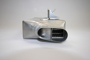
The system enters the continuous aluminum brazing furnace with product being monitored.
Prior to any brazing process, it is important that the substrate surface is prepared correctly to allow the brazing process to work correctly. Surface preparation before brazing may involve thermal degreasing where the substrate temperature is elevated to drive off lubricants. A second more important procedure is the removal of any surface oxide layer to allow wetting, and therefore flow of the brazing filler alloy over the parent substrate. Unfortunately, aluminium is easily oxidized and the resulting aluminium oxide (Al2O3) prevents such wetting processes. Therefore, prior to brazing, the oxide layer needs to be eliminated. In most cases, cleaning of the substrate layer is achieved by the application of a corrosive flux, which in a molten state, dissolves the oxide layer.
A data logger with 10 thermocouple channels.
The type of flux used must be matched to the application substrate and filler alloy composition. A common brazing process used today is that of the Nocolok Process® in which the flux is potassium fluoroaluminate K 1-3 AlF4-6, a white powder deposit.
For the reasons discussed above, elimination of oxygen - and especially water - from the brazing process is a critical requirement, so the furnace is generally run under a nitrogen atmosphere (Controlled Atmosphere Brazing ‘CAB’ Oxygen < 100 ppm, Humidity < -40°F /-40°C). The design and construction of monitoring systems needs to be carefully considered, as discussed later, to ensure that the furnace atmosphere is not contaminated (by oxygen and water), in any way.
Design Principles and Challenges of a "thru-process" Brazing Furnace Monitoring System
The ‘thru-process’ profiling system concept is based on the principle of sending a data logger through the brazing furnace which is protected from the heat and harsh brazing environment by a thermal barrier. Multiple thermocouples connected to the product test piece (radiator), which are connected directly to the data logger, measure the product temperature (and furnace) as it travels through the furnace storing the information in the data logger memory. The resulting temperature profile can be reviewed, analyzed, and a validation report generated. As the system is compact and travels with the product, there is no need to use the cumbersome and potentially hazardous challenge of feeding (and retrieving) long thermocouples through the furnace, as required in the use of traditional trailing thermocouples.
Innovative Thermal Barrier Design
The thermal barrier has the job of providing thermal protection to the data logger. Although this is the case for aluminium brazing, the barrier also needs to be designed in such a way as to avoid damage to itself from potentially hostile corrosive chemicals generated in the furnace, and prevent contamination of the CAB atmosphere from barrier outgassing materials.
Traditionally, thermal barriers are manufactured employing micro-porous block insulation wrapped in high-temperature glass cloth. During use, moisture trapped in the insulation block is released within the barrier cavity where it can form hydrofluoric (HF) acid in combination with chemicals in the brazing flux. Over only a short period of time, the highly corrosive HF acid can cause significant damage to both the barrier cloth and insulation. This compromises the integrity of the barrier, reduces its thermal performance, and potentially creates a dust contamination risk to the process.
Air trapped in the micro-porous insulation block and within the barrier cavity during heating can expand and escape from the barrier into the furnace. Obviously, being made up of 21% Oxygen (O2 (g)), the air will contaminate the CAB environment, and potentially create a risk of aluminium oxide formation resulting in wetting/brazing problems.
To eliminate the damage to barriers, extend operational life expectancy, and minimize outgassing of air (O2(g)) or moisture, PhoenixTM developed a unique new TS08 specifically for the demands of CAB brazing.
As shown in figure 1, the logger draw loading mechanism significantly reduces the amount of insulation cloth that is exposed to the aggressive flux. Prior to supply, the insulation block is preheated in a high vacuum and back flushed with nitrogen (N2(g)) to drive out any air trapped in the porous insulation structure. For processes where any air outgassing is a significant contamination risk, it is possible, with specific barrier configurations, for customers to purge the small barrier cavity of any remaining air with a supply of low-pressure Nitrogen (N2(g)).
Figure 1: The brazing barrier is designed to give low height thermal protection to the data logger. Designed with front loading logger tray and metal construction to limit exposure of insulation and cloth materials to corrosive HF. Available with nitrogen purge facility option to remove any risk of O2 (g) outgassing into the furnace.
PhoenixTM Datalogger with 6, 10 or 20 Channels
Front loading logger tray with encapsulated thermal insulation protecting from HF
Thermal breaks reduce heat conduction to logger
Heat sinks provide additional thermal protection employing phase change technology
Mineral Insulated Thermocouple inserted into radiator fins
Rear barrier optional Nitrogen feed nozzle for pre-run purging of insulation and barrier cavity of air (02(g))
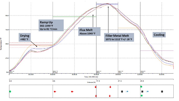
Unveiling the Mystery of your Brazing Furnace with a ‘thru-process’ Temperature Profile Trace
The key temperature transitions/phase of the brazing process are clearly shown on a typical temperature profile as in figure 2.
Figure 2. Thru-process temperature profile of a typical CAB brazing furnace showing critical temperature transitions.
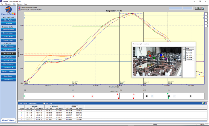
Thermal profile graph displayed in the Thermal View Plus software package.
The brazing system is supplied with Thermal View Plus software, which is designed to provide full analysis and reporting tools for monitoring the brazing process against the monitoring requirements detailed in Table 1.
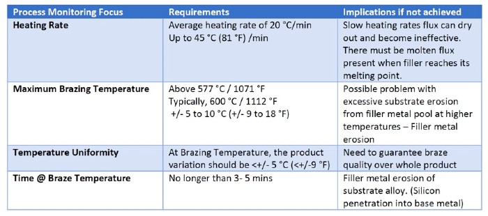
Below in Table 1 is a summary of the target temperature transitions in the CAB brazing process, the impact on process, and possibly, the quality of the brazed final product.
The PhoenixTM brazing system is supplied with Thermal View Plus software, which is designed to provide full analysis and reporting tools for monitoring the brazing process against the monitoring requirements detailed in Table 1.
Table 1. Critical monitoring requirements for the CAB brazing process.
Overview
The PhoenixTM ‘Thru-process’ brazing system provides a rugged, reliable, and clean solution for performing product temperature profiling of Automotive CAB brazing furnaces. Providing the means to Understand, Control, Optimize and Certify the brazing heat treat process.
About the author: Steve Offley, “Dr. O,” the product marketing manager at Phoenix TM, is an experienced global marketing manager with a demonstrated history of working in the industrial temperature monitoring industry over the last 25 years.
If you’ve ever tried to braze together materials that have widely different Coefficients of Thermal Expansion (COE’s), you know that the material with the higher expansion rate will grow faster than the other when heated and contract faster when cooled down. You also know that once the two different materials have been brazed together and cooling begins, the shrinkage-rate differences between those two materials can produce significant shear stresses at the brazed interface between them and be so strong that the thin brazed joint may be torn apart at either interface. Other similar weaknesses and damage can result as well.
In this HTT Best of the Web Technical Tuesday feature, Dan Kay of Kay and Associates, a vacuum and atmosphere brazing consultant, explains the details of this problem and the solution.
Dan Kay Brazing Engineer Kay and Associates
An excerpt: “Today’s brazing technology is based on a strong foundation of the brazing experiences of many people around the world over a period of many decades (even centuries). I’ve now been very active in the brazing world for almost 50 years and, like my predecessors in the world of brazing, I’ve learned a lot about this fascinating joining process (and I’m still learning). In the article, I’d like to share with you one of my brazing experiences from many years back, one that involved high-temperature differential-expansion between an 18″ (45 cm) diameter tool steel die and a thin carbide plate (round disc) that needed to be brazed to the die’s front surface for wear-protection.”
In this article, Dan, who is also a HTT consultant, helps readers understand the high-temp differential-expansion problem, explore what steps can be taken to prevent it, and ties it all together so that readers can clearly understand what to do.
Alessandro Fiorese, R&D Chief Engineer with TAV Vacuum Furnaces SPA
Alessandro Fiorese, R&D Chief Engineer with TAV Vacuum Furnaces SPA, introduces the vacuum brazing process for automotive applications. For more articles, tips, and news related to heat treatment for automotive applications, keep an eye out for Heat Treat Today’s special print/digital issue Automotive Heat Treating, due in June 2019.
Introduction
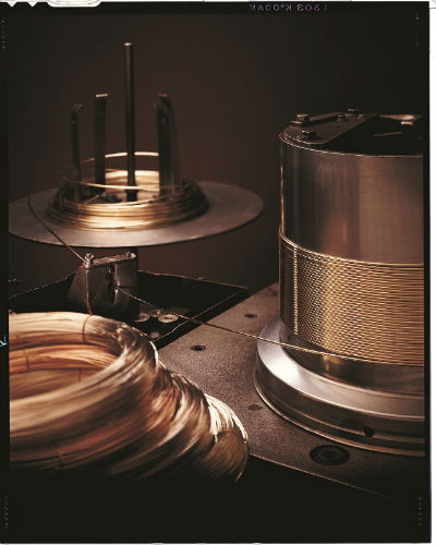
Brazing is a heat treatment process in which metallic parts are joined together through a metallic filler with a melting temperature lower than the melting point of the joined parts. The filler metal can be used as a wire, a thin plate, or a paste depending upon the final application we are considering.
To obtain a good welding in terms of mechanical properties and corrosion resistance, it’s necessary to minimize contamination and impurities in the joined zone. Vacuum brazing processing provides a way to reach a high cleaning level of atmosphere during the brazing heat treatment.
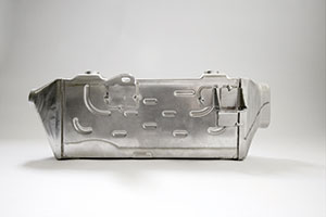
The brazing treatment is particularly useful to produce complex shape parts with a lot of joining points per unit of area. Typical brazing applications are oil or water heat exchangers in the civil and automotive fields such as the ones represented below.
The high-performance aluminum heat exchangers manufacturing is growing particularly in the automotive field. In this context, AA 3xxx and 4xxx are commonly used materials for parts and filler material respectively because these materials have a very low specific weight and a very high thermal conductivity level.
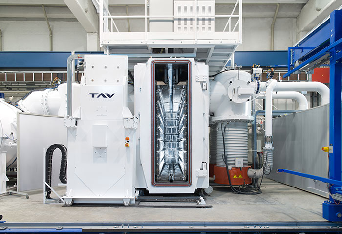
As indicated before, one of the cleanest brazing atmospheres is vacuum. For this reason, in the following discussion, we will analyze in detail the complete characteristics of a semi-automatic TAV vacuum brazing furnace for automotive applications.
Vacuum Brazing Furnace
The entire furnace is composed of three different stations:
the heating furnace;
the loading station;
the cooling station.
Heating Furnace
heating furnace
Furnace Vessel
The vessel separates the inner part of the furnace where the hot chamber is placed from the outside environment. The vessel develops along a horizontal axis, it has an elliptical design and it is provided with two flat doors (front and rear). Both doors are hinged and can be opened manually. The front door has an automatically sliding entrance for loading-unloading the furnace.
Hot Chamber
The thermal chamber has a rectangular section 71 (H) x 18 (W) x 144 (L) inches (180 x 45x 365 cm), and it is constituted by steel panels with nickel-chrome resistors. There are 23 independent hot zones that make the chamber temperature very well-controlled. The temperature uniformity requested for this vacuum furnace is ± 37°F (± 3°C) from the set temperature. In the following picture, the ± 37°F Temperature Uniformity Survey (TUS) chart is shown.
Figure 1. TUS example at a specific temperature with 12 TLC
Vacuum System
The vacuum system has three pumping groups, two with a rotary piston pump, a roots pump, and an oil diffusion pump. The third pumping group has a mechanical pump, a roots pump, and a cryo-trap in order to condensate humidity and impurities released during the entire process. The ultimate reachable vacuum without the load is 10-6 mbar (range).
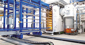
Loading Station
loading station
Loading Baskets
To carry out the brazing heat treatment in a correct way, a specific steel shelved fixtures hold the heat exchangers parts all together with the filler material. For each brazing process, a load from 1984 up to 4850lbs (900 up to 2200kg) can be heat treated at the same time. For gaining a semi-automatic heat treatment process, there is a parking station that can be used as a buffer for the heating furnace.
cooling station
Cooling Station
At the end of the brazing heat treatment, the load is automatically transferred into a separate cooling chamber where the brazed parts are cooled down by forced recirculation of air.
Heat Treatment
Before reaching the brazing temperature, the load is maintained at a lower temperature for a period of time to remove the working oil plate from the heat exchangers. During this maintenance time, a variation between high vacuum and partial pressure of N2 is observed.
Figure 2. Typical brazing cycle. Line yellow is the setpoint, line orange is the temperature TC, line blue is the high vacuum level and purple line is the partial pressure in mbar detected.
After the brazing step, the furnace reaches high nitrogen static partial pressure, starting the cooling phase. This step is considered complete when the furnace injects air up to reach the atmospheric pressure as total pressure. At this time, the front door opens automatically, and the loading track extracts the charge from the furnace.
The space industry is growing fast and is predicted to be worth over a trillion dollars by 2040.
Keith Ferguson, Senior Business Development Manager at Morgan Advanced Materials’ Braze Alloys Business, explains how braze alloys play their part in safe, reliable and sustainable space exploration.
A Braze New World
The saying goes, “one small step for man, one giant leap for mankind.” This famous phrase uttered by Neil Armstrong is the perfect advertisement for space exploration and its importance to the future.
Less than a century old, space exploration has come on leaps and bounds since the first artificial satellite, Sputnik 1, was propelled into space in 1957. Since then, the world has witnessed marvels such as landing on the moon, the space shuttle program of the 1970s, and the launch of the International Space Station.
The importance of these missions and their subsequent value is immeasurable. Many might not realize on a day-to-day basis how space exploration has improved lives and the global economy to no end. This includes simple weather forecasting, broadcasting TV and radio, predicting natural disasters, monitoring for fertile land, forecasting sea level patterns, and even aiding research in muscular atrophy.
It’s little wonder then that this industry has significant value. The space industry was reportedly worth $384 million USD in 2017, growing at a rate of 7.4 percent. According to Morgan Stanley, it sees the industry growing to be worth $1.1 trillion USD by 2040.
However, there are challenges. Many believe that the millions of dollars and resources used to explore space could be better used on immediate threats to society like clean water, famine, poverty and more. Outside of external opinion though, there are internal operational challenges. Namely, space exploration needs to become safer and more sustainable.
A huge part of solving this challenge is in brazing alloys.
A Brief History on Brazing in Space
In simple terms, brazing joins two metals by heating and melting a filler (alloy) that bonds to the two pieces of metal and joins them. The filler must have a melting temperature below that of the metal pieces.
The use of braze alloys in space equipment is mission critical, as they allow sensors to be mounted as close as possible to engines to measure and monitor output and feed data back to operators. Indeed, they’ve already aided successful missions. Two of Morgan Advanced Materials’ braze alloys, RI-46 and RI-49, were specifically engineered and used by NASA on the Space Shuttle Main Engine, also known as the RS25.
Braze Alloys (Morgan in Space)
RI-46 specifically was developed as a replacement for the existing Nioro braze alloy, which is comprised of 82/18 Au/Ni (gold/nickel). RI-46 contains much less gold, adding in copper and manganese instead. This helped make the braze alloy significantly less dense and provided crucial weight savings, but also still operable from a wide range of temperatures, between -400°F to 1292°F (-240°C to 700°C).
These alloys have not only been critical for past space missions, but also for future missions. RI-46 and RI-49 have been adopted for NASA’s Space Launch System (SLS), a vehicle that is planned to take a crewed mission to Mars.
As alluded to already, developing new braze alloys is as much about performance as well as sustainability.
The Need for Non-Precious Alloys
It needs no mention that space exploration is a costly exercise. According to NASA, the average cost to launch a Space Shuttle is $450 million per mission. The Space Shuttle Endeavour, the orbiter built to replace the Space Shuttle Challenger, cost an eye-watering $1.7 billion USD.
Wire Form Braze Alloys (Morgan in Space)
Bringing costs down is clearly required to keep space missions feasible. One key part of cost reduction is in reducing the use of precious metal braze alloys.
Precious metals like gold and palladium are becoming increasingly scarce. Of course, the cost of producing alloys from these precious metals is also increasing as a result.
However, there can be a reluctance to come away from using precious metal alloys. Years of research, development, and data mean these alloys are tested and reliable. When dealing with missions and equipment that run into the hundreds of millions of dollars and, more importantly, the lives of crew members, reliability becomes an overarching objective, and failures must be prevented.
To solve this issue, Morgan’s Braze Alloys business has been researching and developing non-precious metal alloys over many years. As seen from the RI-46 and RI-49 alloys, these solutions are just as strong as their equivalent high precious-metal counterparts, but at a fraction of the cost.
Non-precious metal alloys can be made from metals like nickel, chromium, and cobalt. Their success has already been seen in the aerospace sector, and now research is being pioneered into making them fit for going into orbit and beyond.
Space, for All to Enjoy
Space travel is not just for highly trained astronauts and public benefit; there is also a growing commercial aspect. Satellite TV and radio have already been mentioned, but billionaire entrepreneurs such as Richard Branson and Elon Musk have also been pioneering private space travel. The hope is that civilians might one day be able to enjoy outer space as well, albeit at potentially high prices.
Achieving this dream is of course hinged on safety and reliability, given that lives will be at stake. The key to improving these factors is being able to place sensors as close as possible to the spacecraft’s engine.
By enabling sensors to be placed near the spacecraft’s engine, mission control and crew can then accurately read and measure data and output. This includes fuel efficiency, temperature, gas flow and monitoring for fire detection or abnormalities. If these sensors are placed too far away from the engines, then data readings become inaccurate and missions can be compromised.
Recent news highlights why sensor technologies are critical, as a two-man space crew had to abort their flight to the ISS after a post-rocket launch failure. The Soyuz spacecraft started to experience failure 119 seconds into the flight, and seemingly, problems were reported by the crew first, not by mission control. The crew described feelings of weightlessness, an indication of a problem during that stage of the flight. Luckily, they aborted, ejected their capsule from the rocket, and returned safely to Earth.
While the cause of the failure is still to be identified at the time of writing, clearly, such a situation should not be happening. Any problems should be picked up by mission control, and not be reliant on crew judgment.
Active Alloys join ceramic sensors to engines. (Morgan in Space)
The challenge though is that some sensors are made from ceramic due to the need to resist corrosion and high temperatures, typically up to 1742°F (950°C ). However, these ceramic sensors then need to be joined to metallic parts of the engine.
This is where “active alloys” come in. Unlike regular braze alloys that join metal to metal, these alloys can join metal to ceramic, or even ceramic to ceramic. Industry standard active alloys like Incusil®-ABA and Ticusil® from Morgan’s range were developed up to 40 years ago but are still in use today. New alloys are also currently in development to withstand much higher temperatures.
A Never-Ending Journey
Morgan Metals and Joining Center of Excellence in Hayward, California (Morgan in Space)
Much like how there is still so much to learn and explore about space, so too is Morgan’s journey with braze alloys. Morgan Advanced Materials is not just committed to making the space industry more sustainable and safer, but it is helping with applications across all industries.
A key pillar of this is through Morgan’s highly specialized Metals and Joining Centre of Excellence (CoE), based in Hayward, California, as well as Morgan’s Brazing Department.
With highly trained researchers and scientists, Morgan’s Braze Alloys business can custom cater alloys to specific applications, run trials to test materials, braze cycles and fixturing. The whole operation, from powder atomization, to preform fabrication and brazing trials, can be looked after from start to finish.
Flexicore® (Morgan in Space)
One of the latest developments being pioneered at the Metals and Joining CoE is Flexicore®. This new technology transforms traditionally brittle alloys (such as AMS4777) into a flexible wire form. In many cases, this will be far superior to pastes in terms of repeatability and ease of use. Along with the operational benefits, Flexicore® will also allow for the use of nickel-based alloys to replace precious-metal alloys. Again, this will help to bring costs down for operators and manufacturers.
Watch This Space
Space travel, as Richard Branson predicts for his own Virgin Galactic programme, is only two or three flights away. We’re truly not far away from entering a new world, and brazing alloys will have their say on how the space industry turns out.
Morgan’s Braze Alloy solutions, like RI-46 and RI-49, as well as others like Palniro-1 and Palniro-7, can already be found across the various programmes and spacecraft. Through more research and development, who knows where this important industry could lead us to.
Morgan Advanced Materials plc is a global engineering company headquartered in Windsor, UK , and is a world leader in advanced materials science and engineering of ceramics, carbon, and composites, engineering high-specification materials, components, and sub-assembly parts to solve challenging technical problems. Markets that Morgan work in include healthcare, petrochemicals, transport, electronics, energy, defense, security and industrial.


 Knowing the precise temperature from within your continuous heat treat process is now possible. In this