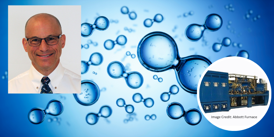
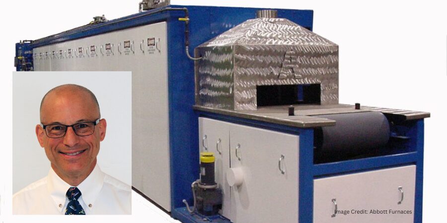
In this installment of Answers in the Atmosphere, David (Dave) Wolff, an independent expert focusing on industrial atmospheres for heat treat applications, examines the cost dynamics of hydrogen as a process gas and the blended atmospheres strategies thermal processors use to manage them. Drawing on insights from Stephen Feldbauer PhD of Abbott Furnace, Wolff walks through the key gas blend options available to operators and how operators select the most cost-effective mix for the job.
This informative piecewas first released in Heat Treat Today’sMay 2026 Sustainable Heat Treat Technologies print edition.
In last month’s column, we discussed hydrogen as a process gas and addressed key attributes. In that column and in the one that follows, Stephen Feldbauer PhD, director of Research & Development at Abbott Furnace, provided key insights.
A Question of Cost
Stephen Feldbauer PhD Director of Research & Development Abbott Furnace
Hydrogen gas is relatively expensive; in fact, case studies conducted by Abbott Furnace have demonstrated that atmosphere costs often constitute over two-thirds of the variable costs of thermal processing. Hence, cost savings in hydrogen-containing atmosphere supply are important.
As a result, thermal processors will preferentially employ gas blends, containing just the right amount of hydrogen to get the job done, diluted in a larger volume of inert or non-problematic diluent gas. Think of it like using a small amount of powerful dish soap diluted with a large volume of water to effectively clean a large amount of pots and pans. The primary advantage to using hydrogen-blended atmospheres is that they are much less expensive than using pure hydrogen.
Hydrogen-Nitrogen Blended
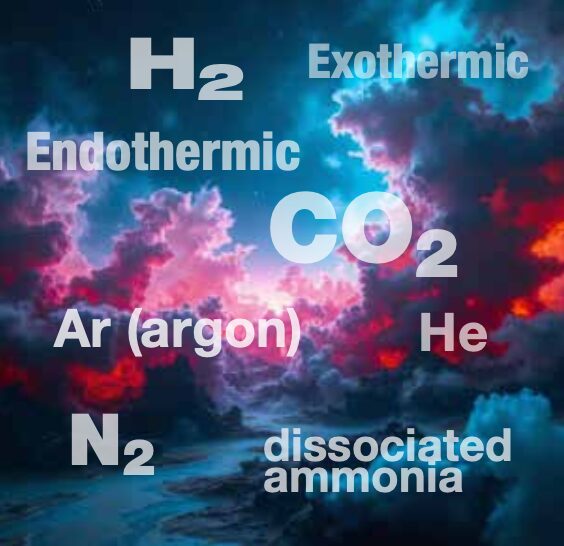
Pure hydrogen, delivered or generated on-site, may be blended with pure nitrogen to reduce atmosphere costs. While nitrogen can be delivered as a gas or liquid, it can also be separated from atmospheric air on-site at low cost to produce a hydrogen-nitrogen blended atmosphere. Hydrogen-nitrogen blended atmospheres typically range in hydrogen content from about 3% to 75% hydrogen, with the balance nitrogen. Nitrogen costs the thermal processor about 20% of the cost of hydrogen for a similar volume of gas, so blending hydrogen with nitrogen may be a useful approach to obtaining the benefits of a hydrogen-based atmosphere at substantially lower cost.
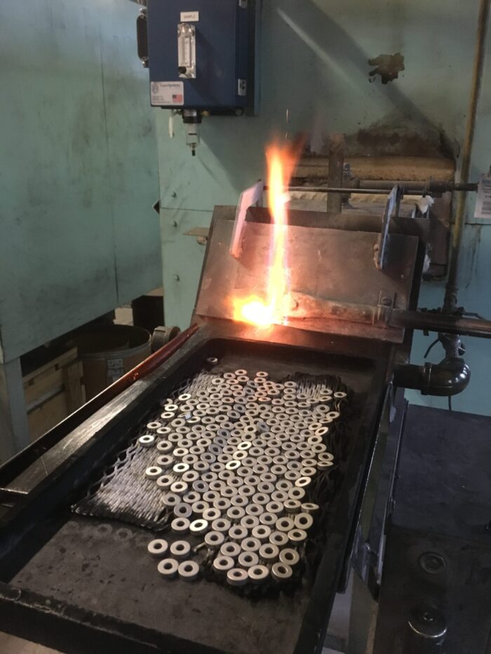
The actual blend of hydrogen and nitrogen used is primarily determined by the metal that is being thermally processed. As the oxide of one metal may be more stable and difficult to reduce than another, the amount of hydrogen is often increased to make the atmosphere more active. Some metals will be adversely affected by nitrogen at high temperatures. Thermal processors using a hydrogen-nitrogen atmosphere will use furnace atmosphere mixers to blend the leanest (lowest hydrogen) atmosphere that yields acceptable results in the finished metal parts.
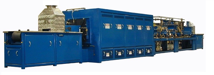
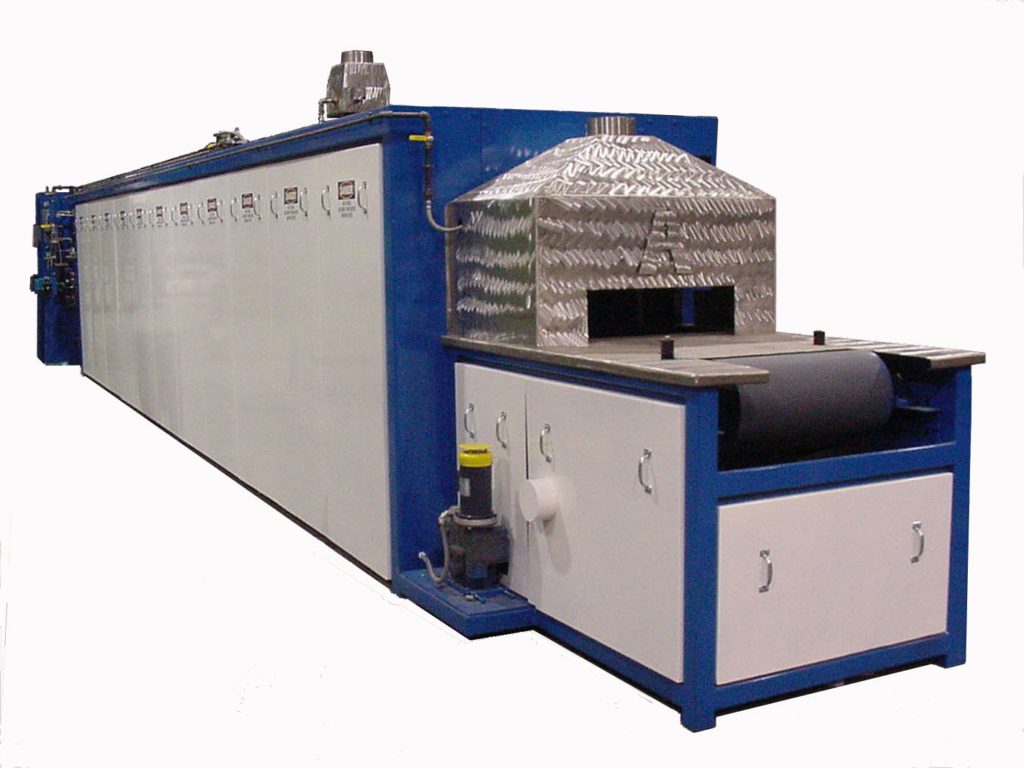
Image Credit: Abbott Furnace
A widely used generation approach to a hydrogen-nitrogen atmosphere is to use a thermal catalytic reactor (a “dissociator”) to crack metallurgical grade ammonia (NH₃) to a gas blend of nominal 75% hydrogen, 25% nitrogen (based on the ratio of nitrogen and hydrogen atoms in the ammonia starting gas). Because ammonia is a commonly used agricultural and industrial chemical, ammonia is widely available and cost-effective. Ammonia is delivered by truck in pressurized liquid form and stored in a tank for use.
The resulting atmosphere gas blend is generally called dissociated ammonia (DA). Significantly less expensive than using pure hydrogen, DA gas is a popular gas blend if a nitrogen-containing gas blend can be used. If decreased reducing potential is acceptable, generated DA gas can be further diluted with pure nitrogen to reduce costs even more.
Generation from Hydrocarbon
Another approach to cost-reducing hydrogen-containing atmospheres is to generate a hydrogen-containing atmosphere from a readily available hydrocarbon, such as natural gas, propane, or even methanol. This is possible because these hydrocarbons can be thermally cracked using a catalytic reactor to liberate free molecular hydrogen gas in a blend with other constituents. These reactors may use partial combustion in the case of Exothermic reactors to make Exo gas, or they may use pure thermal cracking, avoiding combustion, in which case the technique is called Endothermic gas generation, and the resulting gas is often called Endo gas.
Because Exo gas is a result of partial combustion with air, an Exo gas blend has approximately 10% hydrogen and considerable nitrogen in it, whereas Endo gas has approximately 40% hydrogen and very low levels of nitrogen. Because both Exo and Endo gases contain considerable carbon (originating from the fuel gas), their uses are limited to processes and materials where the carbon content does not create processing issues.
Argon-Hydrogen Blend
Many of the stainless steel grades cannot be thermally processed in nitrogen-containing atmospheres because the nitrogen gas will react with the chromium, damaging the alloy. In that case, an argon-hydrogen blend may be employed. Because argon is more expensive than hydrogen, the economics of an argon-hydrogen gas blend may result in much higher levels of hydrogen in the furnace atmosphere.
About The Author:
David (Dave) Wolff Industrial Gas Professional Wolff Engineering
Dave Wolff has over 40 years of project engineering, industrial gas generation and application engineering, marketing, and sales experience. Dave holds a degree in engineering science from Dartmouth College. Currently, he consults in the areas of industrial gas and chemical new product development and commercial introduction, as well as market development and selling practices.
What if durable hydrogen production design was approached from the standpoint of optimizing data analysis and controls management? When addressed as such, onsite generation can simplify deployment, reduce upfront integration risk, and enable flexible scaling for applications ranging from backup power to industrial processing. Anya Bharadwaj, product manager at Fourier Earth, examines how two North American heat treating operations — one induction, the other sintering — have leveraged software-defined modularized hydrogen to capture these advantages.
This informative piece was first released in Heat Treat Today’sApril 2026 Annual Induction Heating & Melting print edition.
In the high-stakes world of advanced manufacturing, the atmosphere inside a furnace is as critical as the temperature. For decades, manufacturers have been tethered to a legacy, delivery-based model for their hydrogen supply. This energy ecosystem is increasingly showing its age, plagued by hazardous storage conditions, supply chain shocks, and logistical costs that can balloon to 7–10x the actual production costs.
Recent changes in modular electrolyzer technology challenge the delivery-based hydrogen model by enabling on-site generation directly at industrial facilities. One such approach seeks to reimagine energy distribution and storage — when, and how it is needed most. Two case studies illustrate how intelligent, software-defined systems improve reliability, reduce logistical risk, and better align supply with real-time process demand.
Achieving Scalability with PEM Electrolyzers
This system utilizes Proton Exchange Membrane (PEM) electrolyzers to split water into hydrogen and oxygen by applying electricity across a solid polymer electrolyte membrane. Water is fed to the anode side, where oxygen is ionized into positively charged ions (protons) and negatively charged ions (electrons). The protons pass through the membrane while electrons travel through an external circuit (creating the electrical loop). The protons recombine at the cathode to form hydrogen gas.
PEM systems are well-suited for dynamic operations because they respond quickly to changes in power input, operate at relatively high current densities, and produce high-purity hydrogen without requiring a separate gas purification step.
Figure 2. Fourier electrolyzer system displayed at customer site | Image Credit: Fourier
Unlike large, monolithic MW-scale electrolyzers that are complex to integrate and difficult to optimize, PEM stacks can be designed in modular units (Figure 2). Electrolyzer efficiency does not inherently improve with size, so instead of scaling up into single massive systems, the design is scaled out — splitting capacity across many smaller modules without sacrificing performance. Modularization improves lifetime and efficiency since each stack can operate at its optimal temperature, pressure, and current density.
In this architecture, variables in hydrogen production across hundreds or thousands of stacks need to be controlled and optimized. Fourier’s software-defined energy system materialized from seeing hydrogen production as a data and controls problem first and foremost. This hardware-software feedback loop combines machine learning and modular hardware to monitor and control such variables as temperature, pressure, and density.
While on-site hydrogen generation overcomes centralized hydrogen production challenges, seamless integration requires a system that functions as a distributed, intelligent energy resource. The modular architecture is driven by advanced algorithms that optimize performance in real-time, constantly adjusting to deliver peak efficiency and reliability. For modern heat treat operations, this is a crucial step to overcome the technical and commercial barriers due to transportation challenges and volatile industrial gas pricing.
Case Study 1: The Heat Treatment Facility
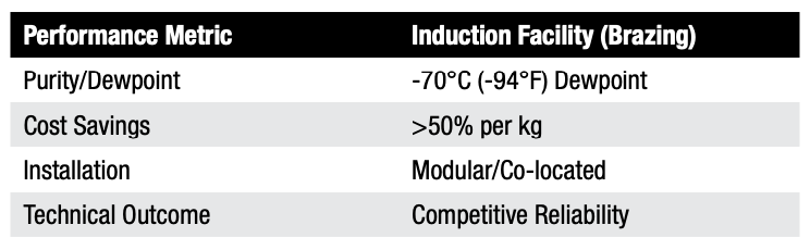
Table A. Performance metrics for induction brazing
The primary objective of the first pilot deployment at an induction heat treatment facility in Southern California was to generate a supply that matched the rigorous reliability and purity requirements of their brazing process. For high value components being induction brazed, hydrogen removes surface oxides from metals, preventing oxidation and improving the quality of the heated workpiece. Any supply interruption or purity dip can compromise their integrity.
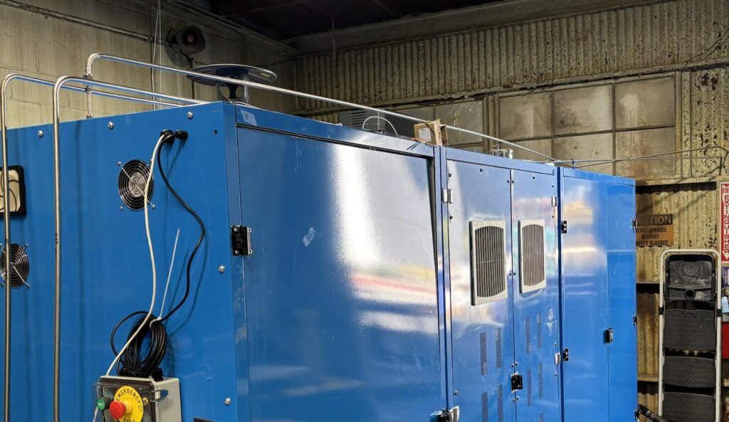
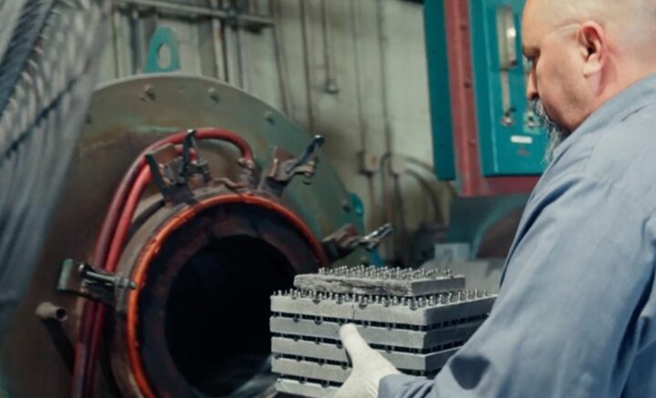
In September 2025, the first modular electrolyzer unit was deployed (Figure 1). The integration process involved:
Direct connectivity: The unit co-located at the site and connected directly to the existing electric panel and water supply.
Zero-disruption tie-in: The system integrated directly into the facility’s existing hydrogen manifold, essentially replacing the delivery truck with a continuous on-site stream.
Technical excellence: Over a four-week pilot, the system met stringent specs — a -70°C (-94°F) dewpoint and 60 PSI pressure — supplying hydrogen for two brazing furnaces.
Figure 1. Metal parts being loaded into furnace running on Fourier hydrogen at heat treatment facility, CA | Image Credit: Fourier
During the pilot, hydrogen quality was monitored through continuous dew point and pressure sensing, with all data aggregated into a central dashboard to track moisture levels, delivery stability, and overall system performance in real time. Dew point served as a critical indicator of gas dryness, since excess moisture would directly increase oxidation risk at high-temperature induction heating. Pressure monitoring ensured steady flow and confirmed system integrity throughout each run.
Although a formal gas chromatography was not conducted during the pilot, purity was validated through application-level outcomes. Each treated batch of metal was inspected post-processing, and clean, bright surfaces were consistently observed without scale, pitting, or discoloration. Because hydrogen acts as a reducing atmosphere, even minor deviations in moisture or composition would quickly appear as visible defects. This aligned with stable sensor data and consistent operating conditions. This real-world validation is commercially meaningful: in induction heating, surface quality directly affects downstream machining, coating adhesion, and yield. Demonstrating repeatable, oxide-free results confirms both technical robustness and economic value under actual production conditions.
The successful proof-of-concept achieved industrial-grade performance and reduced costs by more than 50% on a dollar-per-kilogram basis compared to what the client was paying under the existing hydrogen contract.
Case Study 2: Compax, Inc.
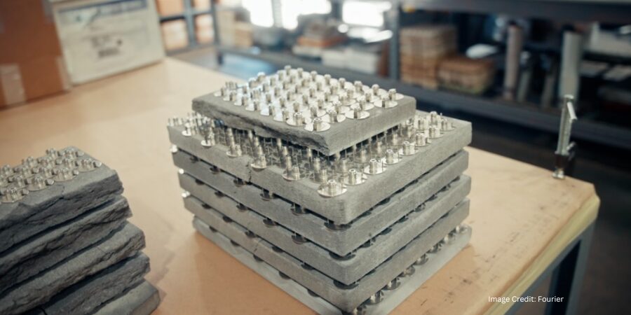
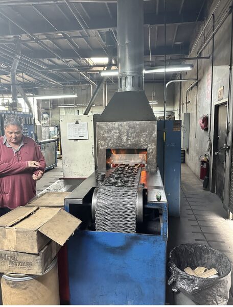
Figure 3. Furnace running on Fourier hydrogen at powder metal plant, Compax, CA | Image Credit: Fourier
For the second pilot development at Compax, Inc., a leader in powdered metal manufacturing located in Southern California, the challenge centered on sintering. Compax uses hydrogen to eliminate oxygen during the heat treating process (Figure 3). The facility faced frequent price hikes and the looming threat of supply disruptions that could halt their belt sintering furnaces, a risk the company sought to eliminate.
The pilot deployment at Compax in November 2025 further proved the scalability of the design — modular units inspired by the data center world, easily configured to specific site needs. The integration process involved:
Rapid deployment: Within just two days, the team fully brought the system online in Compax’s utility infrastructure.
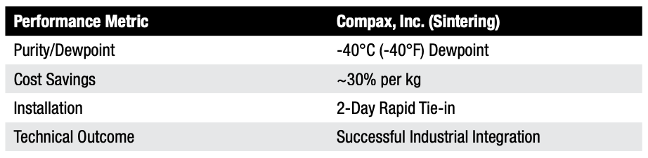
Tailored performance: The system delivered a flowrate of 255 SCFH at a -40°C (-40°F) dewpoint and 10 PSI, precisely optimized for the powdered metal sintering process.
Operational control: According to Earl Johnson, CEO of Compax, the system “reliably produced hydrogen…without the hassle of transportation,” adding that it provided much needed “flexibility against frequent increases in industrial gas prices.”
Table B. Performance metrics for sintering
Implications for Industrial Heat Treating
Both pilots achieved a structural advantage by removing logistical constraints, proving that this type of software-enabled hydrogen generation is a viable, cost-effective solution for industrial decarbonization.
By shifting from a centralized commodity model to a distributed, intelligent energy resource, manufacturers gain more than cheaper gas; they gain independence from hydrogen delivery. As the heat treat industry faces increasing pressure to decarbonize while maintaining razor-thin margins, modular, data-driven approaches offer a practical solution, lowering local emissions and ensuring on-demand production.
About The Author:
Anya Bharadwaj Product Manager Fourier Earth
Anya Bharadwaj is a product manager at Fourier Earth, where she leads product strategy and go-to-market for modular hydrogen electrolyzer systems. Her work focuses on identifying new market opportunities and deploying hydrogen technologies for long-duration energy storage and industrial decarbonization. She holds an MBA from Stanford Graduate School of Business and previously worked in energy investment.
In this installment of Answers in the Atmosphere, David (Dave) Wolff, an independent expert focusing on industrial atmospheres for heat treat applications, examines the powerful reducing properties and high thermal conductivity that make hydrogen a critical atmosphere in metal thermal processing.
This informative piece on hydrogen’s role in sintering, annealing, and surface protection — including how it is sourced, how it behaves inside the furnace, and how operations can safely manage this flammable atmosphere under NFPA 86 —was first released in Heat Treat Today’sApril 2026 Annual Induction Heating & Melting print edition.
Hydrogen is widely used in metal thermal processing for sintering of powdered metal fabrication technologies and for heat treatment (e.g., annealing, brazing) of bulk metal manufactured components. This column draws heavily from an interview the author had with Stephen Feldbauer Ph.D., director of Research & Development at Abbott Furnace. Abbott Furnace is a leading furnace manufacturer for continuous furnaces and furnace controls. As R&D Director, Steve leads Abbott’s work in pioneering furnace advances with a special focus on debinding and sintering.
Why Hydrogen?
Stephen Feldbauer, PhD Director of Research & Development Abbott Furnace
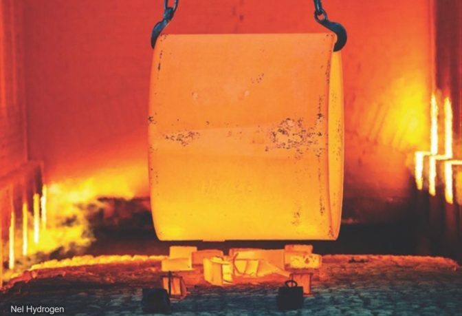
Hydrogen provides two desirable characteristics to heat treaters: very high chemical reducing potential and the highest thermal conductivity of any gas. The high reducing potential enables hydrogen to convert heated metal oxide coatings to pure metals. This is extremely helpful for successful sintering of powder metallurgical parts. Superior thermal conductivity enables rapid part heat up and cool down. Compared with either vacuum or inert gas atmospheres, hydrogen enables much faster throughput and achieves shorter furnace cycles.
Hydrogen-containing atmospheres are required to successfully sinter most iron-based metal parts, whether manufactured by powder metallurgy (PM), metal injection molding (MIM), or binder-jet metal additive manufacturing techniques. As-received, the iron-containing metal powders used for these advanced fabrication techniques are covered with an iron-oxide coating, making it virtually impossible to successfully sinter the particles together under reasonable temperature conditions. Reducing the oxide coating enables successful sintering.
Hydrogen-based atmospheres used with a tube or strand furnace are the primary surface protective technology used for drawn components (e.g., wire, tubing, and profiles). Hydrogen simultaneously protects the part surface from oxidation and allows metal to anneal, which softens it and restores toughness after it has been hardened by the drawing process.
Sourcing Hydrogen
Because of its high reactivity, hydrogen is almost never found in nature as a pure gas (H2). Instead, it is generally found as a component in a compound like water (H2O) or a hydrocarbon gas or liquid, such as methane (CH4), propane (C3H8), or longer hydrocarbon. In order to be used as a thermal processing atmosphere, hydrogen is liberated from these hydrogen-containing compounds to exist as a pure gas while in use in the hot furnace.
The liberation of elemental hydrogen from its compound carrier can happen at a remote plant operated by an industrial gas company provider, in which case the hydrogen would be compressed or liquified for delivery to the thermal treatment client, or may be conducted at the site of the thermal processor themselves through use of on-site generation equipment. User choices of approaches to pure hydrogen supply will be covered in future columns.
Inside the Furnace
Inside the hot furnace, hydrogen changes metal oxide coatings to pure metals by preferentially reacting with the metal oxides to produce pure metal and water vapor. Thus, the furnace atmosphere dewpoint (a measure of gaseous water content) will increase as the hydrogen simultaneously creates pure metal surfaces and produces water vapor as a byproduct. The water vapor is swept out of the furnace and replaced by the clean furnace atmosphere that flows counter current to the heated metal product. Furnace atmosphere controls for hydrogen-based atmospheres use dewpoint as a key operating parameter.
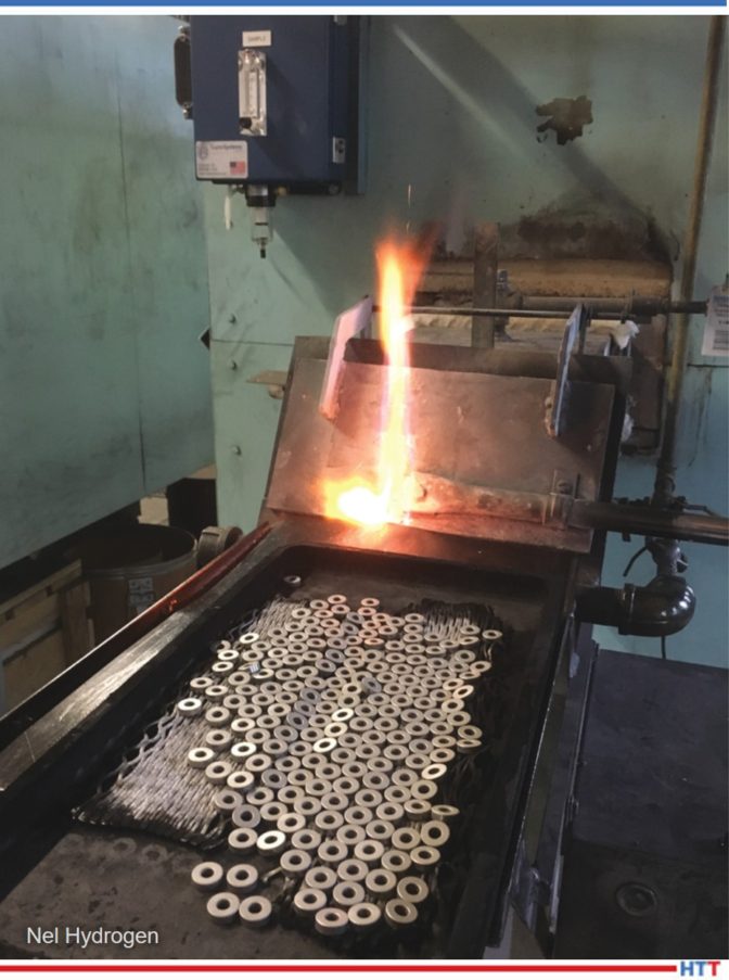
Hydrogen’s ability to protect the part surface from oxidation is critical in the annealing process. | Image Credit: Abbott Furnace
Since furnaces must open to admit parts for thermal processing, the furnace, the atmosphere system, and the procedures must all be designed to prevent unsafe conditions caused by hydrogen leaking out of the furnace, or air leaking in. Furnaces intended for a flammable gas atmosphere use doors, curtains, and pilot lights (i.e., flame curtains) to prevent hydrogen or other flammable gas from leaving the furnace without being combusted. These precautions avoid explosions inside or outside the furnace.
Furnaces for hydrogen-containing atmospheres utilize unique design and construction approaches to safely use this flammable atmosphere. In the U.S., furnace design and operation is guided by NFPA 86, the furnace code. NFPA 86 defines certain furnace design features and also defines standard operating techniques for safe operation with a combustible atmosphere, such as a hydrogen-containing atmosphere. Similar codes and standards are used in other countries.
Next month, this column will pick up the question of cost by looking at options for generation of hydrogen atmosphere blends. Generation of pure hydrogen will be a future topic.
About The Author:
David (Dave) Wolff Industrial Gas Professional Wolff Engineering
Dave Wolff has over 40 years of project engineering, industrial gas generation and application engineering, marketing, and sales experience. Dave holds a degree in engineering science from Dartmouth College. Currently, he consults in the areas of industrial gas and chemical new product development and commercial introduction, as well as market development and selling practices.
Heat Treat Todayis pleased to welcome this regular column spot, Answers in the Atmosphere, to David (Dave) Wolff, an independent expert focusing on industrial atmospheres for heat treat applications. This column explores various atmospheres with Dave and different industry specialists.
This informative piece on the critical role of atmosphere control in metal thermal processing was first released inHeat Treat Today’sOctober 2025 Ferrous & NonFerrous Heat Treatments/Mill Processing print edition.
Thermal processing of metals is critical to successful production of fabricated metal parts and assembled systems. Characteristics of parts and devices, including blades, springs, wire and cable, medical implants, and electric motors, all depend on successful thermal processing to produce metallic components with specific properties to meet the requirements of the part, assembly, or device. What is sometimes overlooked, however, is that atmosphere is as critical as the heat itself. The wrong furnace atmosphere can undo the best processing recipe, while the right one ensures that parts achieve their intended properties consistently.
Tune into the news, and you will find stories about metal parts incorrectly handled during thermal processing: gears that degrade to powder, camshafts that were too soft, electric switches that fail, materials with the wrong magnetic properties, knives that cannot hold an edge, and so on. These are all problems that occur too frequently and are expensive to resolve, because metal parts are often components in a more complex and expensive assembly. (Imagine the responsibility of parts-making for military jet engines or body-implanted parts. You do not want to be the shop supplying inadequate parts!) It is imperative that heat treating and sintering processes are completed correctly the first time.
Metals thermal processing requires more than just heat. As indicated above, atmosphere is essential to the heat treating process, coming alongside temperature, time, and a specific sequence of operations in a recipe that will ensure the material yields the desired performance. Much like baking bread, thermal processing of metals requires equipment, materials, conditions, and recipes. The furnace is the main equipment (other operations may be performed in a less expensive thermal processing oven). Then there are the materials — the parts being heat treated — which may be bulk metals, alloys, or compacted powder parts with unique blends and surface morphology. The conditions of time, temperature, atmospheres, and perhaps a quenching step come together in a specified recipe. Properly done, heat treating and sintering operations will yield parts that meet the hardness, toughness, appearance, surface finish, shape, dimensions, and other specialized and specified properties.
Since cost is an important driver, metals thermal processors strive to produce compliant parts in as few steps as possible. Innovations can assist in making it possible to consolidate steps, too. But mistakes in thermal processing may result in defective parts or require expensive rework or even additional (secondary) operations to correct deficiencies.
Each issue, this column will focus on the atmospheres component of heat treating. You’ll read interviews with industry experts focused on the atmospheres used in thermal processing — from relatively inert atmospheres, such as vacuum, nitrogen, and argon, to chemically active atmospheres used for annealing, hardening, and sintering. We will assist thermal processors by explaining how various atmospheres work, what the key properties are that determine successful results, how to buy and utilize the atmospheres, and precautions and alternatives for that atmosphere.
My hope is that this column will help Heat TreatToday readers become better buyers and users of atmospheres, so that you can run a smoother, more reliable, and more profitable operation.
About The Author:
David (Dave) Wolff Independent expert focusing on industrial atmospheres for heat treat applications
Dave Wolff has over 40 years of project engineering, industrial gas generation and application engineering, marketing, and sales experience. Dave holds a degree in engineering science from Dartmouth College. Currently, he consults in the areas of industrial gas and chemical new product development and commercial introduction, as well as market development and selling practices.
Hydrogen is essential for many heat treating processes, but what happens when your supply runs out?
In today’s episode of Heat TreatRadio,Devon Landry of Nel Hydrogen joins Heat TreatRadioHost Doug Glenn to discuss the potential risks of delivered gas and how on-site generation can secure reliable, high-purity hydrogen. This episode highlights the advantages of on-site generation and what questions to ask before making the switch.
Below, you can watch the video, listen to the podcast by clicking on the audio play button, or read an edited transcript.
The following transcript has been edited for your reading enjoyment.
Hydrogen Usage in Thermal Processing (4:05)
Doug Glenn: All right, let’s talk hydrogen. I think the first thing I’d like to do is talk about the basics, how hydrogen is used and what it’s used for in thermal processing.
Can you give us a 30,000-foot view on hydrogen and why are we using it in thermal processes?
Devon Landry: Hydrogen is widely used in heat treat and processing. It’s a powerful reducing agent for surface cleaning and sintering success.
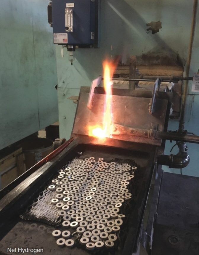
Hydrogen scavenges oxygen, counteracting minor furnace leaks. Photo Credit: Nel Hydrogen
It has the highest heat conductivity of any gas, so we can enter and exit parts quicker. It has lower density relative to air and nitrogen, which makes it really straightforward to manage. It burns off easily, readily, cleanly. The only true byproduct of that would be water.
Doug Glenn: We are talking about the security of hydrogen supply.
How important is it for people who need hydrogen to have it, and what happens if they don’t have it — what are the risks here?
Devon Landry: My predecessor, Dave Wolff, used to say it’s like yeast for a pizzeria. It’s a very small part of the cost, but if you don’t have yeast, you don’t have pizza. If you don’t have pizza, you don’t have business. So if you don’t have hydrogen, you can’t really run your processes.
The same with running out of hydrogen. If you’re halfway through a batch and you run out of hydrogen, that whole batch is done. If that batch isn’t finished and you don’t have any hydrogen left, you don’t have business. You have to send employees home and stop your production. You can run into a lot of problems.
Doug Glenn: If you’re processing high-value parts, it’s not just a matter of simply running out of parts and not being able to finish the load. That load could be worth a quarter of a million dollars.
Devon Landry: That’s correct, the parts are completely done; you won’t be able to use those parts — it’s a completely wasted batch. So, you would lose money, not just from excess production, but that batch as well.
On-Site Hydrogen Generation vs. Supplied (06:25)
Doug Glenn: There’s different ways of getting your hydrogen, it can be supplied or Nel, the company you’re with, supplies the equipment to manufacture hydrogen on-site. What type of risks are companies exposing themselves to if they are not generating their own hydrogen?
Devon Landry: Delivered hydrogen is really the only other way to get your hydrogen, and that’s through industrial gas suppliers. I see a shortfall in the future, especially with liquid hydrogen production. There are many hydrogen plants that are getting canceled or delayed.
Supply chain and hydrogen requirements for Artemis rocket
You see, it costs a lot of money to make these plants, and if the financial advisors deem that the plant is not going to make money, they’re not going to do it.
For the Artemis rocket, that takes a full day’s production of liquid hydrogen in the U.S. to fill up. And there are many projects out there that are requiring liquid hydrogen, which is why I see a shortfall coming.
If you can’t get the hydrogen from your industrial gas supplier, where are you going to get it?
That’s where Nel Hydrogen comes in. With generating on-site, you take control of your hydrogen supply.
Doug Glenn: You mentioned that you foresee a lack of supply and that some of these hydrogen plants aren’t being approved.
Why aren’t these plants being approved to be built?
Devon Landry: They cost a lot of money to build and industrial gas companies have a long-term strategic focus, with capital discipline kind of upfront. If you’re going to build a plant and shareholders are not going to see any returns on it, then they’re not going to do it.
So we’ve seen a lot of cancellations. They haven’t really have a good commitment to shareholder value, and they emphasize on strong fundamentals there.
Doug Glenn: At one point in time, there was a lot of talk about hydrogen fuel cells. And everybody wanted to do hydrogen. I haven’t heard much about that recently. Do you think that might have something to do with the cooling off of the hydrogen market?
Devon Landry: Yes, I think so. There was a hydrogen world out there, and people really wanted to build new plants, have fueling stations. There’s so much you can do with hydrogen. But policies around hydrogen are affected by different administrations. With the current administration, they’re taking some of those incentives away. So there’s not as much money being provided as an incentive.
Doug Glenn: This is all the more reason to be very careful about your hydrogen supply. Not only your current hydrogen supply, but in the future. With politics and different administrations, sometimes hydrogen fuel cells is on, then it’s off. As a result, supplies may be a bit dicey. Therefore, it’s probably well worth people paying close attention to where they’re getting their hydrogen now and what the future looks like.
Your input is really important here.
Proton Exchange Membrane (10:23)
Hydrogen cleans part surfaces to enhance processing results. Photo Credit: Nel Hydrogen
Doug Glenn: Tell me about PEM; what does that stand for?
Devon Landry: PEM stands for proton exchange membrane. It’s a differential pressure system, where hydrogen is allowed to pass through the membrane but oxygen cannot.
We’re taking ultra pure water with a resistivity of greater than one mega ohm. That’s going through into the cell stack and the electrolysis takes place there. The hydrogen is allowed to pass through that membrane; the oxygen is not. So, the hydrogen goes towards the process.
Doug Glenn: Oxygen and/or water is the only byproduct.
Devon Landry: Yes, and it returns to the main reservoir, and that oxygen gets vented, either out of vent stack or into the room.
Doug Glenn: The primary markets that Nel Hydrogen serves are mostly industrial, and Nel can also do much larger units. Can you tell me about that?
Devon Landry: With alkaline and PEM both, we can do megawatt style units. I handle primarily the industrial units, and we can go all the way up to 100, 200, 300 megawatt systems — a very vast range.
Doug Glenn: Most businesses in our industry would not need that much, but it’s good for our people to know that you guys have expertise, not just in the sizes that are good for them, but larger sizes as well.
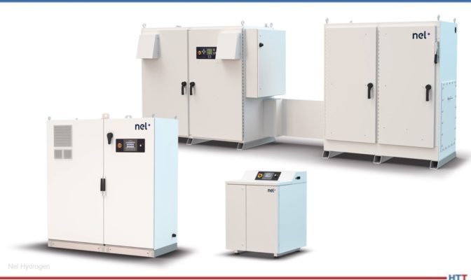
Nel Series hydrogen generators Source: Nel Hydrogen
PEM Process vs. Alkaline (12:05)
Doug Glenn: We have discussed the PEM process. Can you explain the difference between how the hydrogen is extracted from the PEM process vs. alkaline?
Devon Landry: The alkaline system uses KOH, which is highly corrosive and dangerous to handle. You have to fill it up, so there’s a safety aspect with that. In addition, the purity that you’re getting out of the alkaline process is not quite as high as PEM. I think it’s 90%, but it can be 97 to 98%.
With the PEM process, the only output you’re getting is hydrogen and some water, and we mitigate that water with a dryer inside the system. We get five nines purity plus: 99.999% purity plus.
You really need that purity in a lot of the heat treating processes to give you the coloration of the pieces that you’re putting through. With the industrial gas suppliers, you often have to pay a premium to have higher purity. Many times, when you send those cylinders or a tube trailer back to get it refilled, they do not test it to find out exactly what the purity is unless you specifically request that. So your purity might differ every now and then, which means you’re not going to get the exact effect on your process that you would like.
The way the industrial suppliers are making that hydrogen is through steam methane reforming. It’s very energy-intensive, and carbon is a major by-product of that process.
Our machines are as carbon free as your electricity supply line: if you’re feeding it with solar and wind energy sources, utilizing renewable energy, then you are at a zero carbon footprint.
Doug Glenn: You would have true green hydrogen. If your electricity supplier was green, then you would be really producing green hydrogen, which would be very good.
Delivered Gas vs. Hydrogen Generation (14:55)
Doug Glenn: What questions should companies be asking if they are considering moving away from bulk or delivered gas to on-site hydrogen generation?
Devon Landry: To have a hydrogen generator on-site, you need to know your flow and your pressure. There are going to be operational and capital costs.
The capital costs are a little larger with the hydrogen generator. So you’ll need to know how much gas you’re using and what pressure you’re using at. We have calculators to determine which unit would be best for you based on those questions.
If the capital costs are a little too high, which they are for some companies, then we do have leasing options that will help with that capital cost. We can break it down monthly, even for a 10-year period of what you would be spending for your delivered gas versus a hydrogen generator on-site.
Doug Glenn: So, you can do that analysis for businesses if they can provide their current expenditures for delivered hydrogen and usage, and then you can do a comparison to advise them on what it would cost if they were to transition to on-site generation?
Devon Landry: Yes, exactly. Industrial gas suppliers can come with a lot of bills, so you have to pay attention. There could be a trailer rental fees, cylinder rental fees, delivery fees — a lot of bills combining into one. They also generally require signing a contract with them that could be seven plus years, and you have to provide quite a long notice to be relieved of those contract obligations as well.
Doug Glenn: The capital cost could potentially be different, meaning probably more for an on-site generator for hydrogen. When you think of bulk gases, the operating costs are quite low for delivered gas.
How about operational costs for hydrogen?
Devon Landry: The cost of hydrogen generation is going to be the cost of your electricity. The price per kilowatt is going to tell you how much cost per standard cubic foot that you’re going to be paying for it.
Doug Glenn: Electricity is really the only major cost operationally. How about maintenance costs?
Devon Landry: The maintenance cost depends on which machine you select. We build maintenance costs right into the calculator that tells you how much the costs will be per year. There’s a quarterly maintenance cost, which is just basically a calibration, and then a yearly maintenance kit that you can put in yourself.
Doug Glenn:Do you need to have any special personnel to run it or is it self-maintaining?
Devon Landry: It pretty much takes care of itself. If there’s a problem with it, a pop up will let you know the problem, and you can go to the manual to learn exactly what the problem is. If you have a regular maintenance crew on site, many power plants have these, then you usually have somebody that can do it.
It’s generally filter changes and updates like that.
Community Perception on Hydrogen Generation (18:25)
Doug Glenn: Pertaining to public perception, how has the community responded to hydrogen generation?
Devon Landry: Most people like it better. We like to refer to it as the good neighbor benefit. Would you rather look outside and see a gigantic tank full of combustible gas or a quarter inch, stainless steel line?
Fire marshals love it because we store less than seven standard cubic feet on our biggest machine, internally.
And then when we hit the stop button, or if the generator shuts down, the hydrogen is all vented out into the atmosphere. There’s no stored hydrogen — only a minimal amount inside the machine.
Doug Glenn: No rocket ships in your backyard.
Devon Landry: Looking out the window, I’d rather see the sky and some bushes rather than a big tank.
Is Hydrogen Generation Right for Your Company? (19:30)
Doug Glenn: Are there instances where generating hydrogen on-site doesn’t make sense for a company or when bulk delivery is a better deal?
Devon Landry: This is why we have those calculators. I don’t need a company buying a generator if it’s not going to save them money or if it’s not going to be easier for you. It’s really only practical when you’re under 10,000 standard cubic feet per hour.
Doug Glenn: Is that amount for a very large industrial manufacturing plant?
Devon Landry: Yes, that’s quite a bit.
Doug Glenn: Is there any amount that’s too small in which it wouldn’t make sense to have a generator?
Devon Landry: No, our smaller generators put out about 10 standard cubic feet per hour, about 4.9 liters per minute, and it’s on-demand. If you need the smallest amount possible, they’ll put that out for you. If you don’t need any further for the interim, it will basically sit there in idle. These generators are fully on-demand and give you exactly what you need.
Doug Glenn: Which companies currently are out there that it really makes sense for them to look at on-site hydrogen generation?
Devon Landry: Really, anybody that needs hydrogen. If you’re not excited about your delivered hydrogen, if you’re having issues with it, if the cost is too high, we have a lot of different industries that we run with. Many are heat treating and metal processing business. There’s also chromatography, gas chromatography, MOCVD, many different industries. If you have delivered hydrogen, generating hydrogen on-site would be worth looking into.
Final Thoughts (22:45)
Doug Glenn: Where is the corporate headquarters or the world headquarters for Nel Hydrogen?
Devon Landry: Nel Hydrogen is headquartered in Oslo, Norway.
Doug Glenn: How long has company existed?
Devon Landry: It started in 1927.
Doug Glenn: Where’s the main headquarters in the U.S. or North America?
Devon Landry: We’re in, Wallingford, Connecticut, and all of our PEM machines are built there.
Doug Glenn: Very good. I’d like to thank all the everyone for listening.
Hopefully you found this episode enjoyable and informative. Thanks again, Devon. Appreciate you being here.
About the Guest
Devon Landry Senior Field Engineer and Technical Lead Nel Hydrogen
Devon Landry has been an integral part of Nel for 16 years, establishing himself as a leading expert in industrial on-site hydrogen generators. With over 15 years as a Senior Field Engineer and Technical Lead in Technical Service and Customer Support, he has played a key role in delivering top-tier service and expertise to Nel’s global customer base. His extensive experience includes traveling more than 3 million miles worldwide, working across diverse industries and customer sites.
Beyond his technical proficiency, Devon brings strong leadership and business acumen. As an entrepreneur, he successfully founded and managed a craft brewery and taproom in Connecticut for six years, leading a team of seven employees. This experience further enhanced his ability to blend technical expertise with strategic management and operations.
Exothermic gas undergoes a few metamorphoses from the time it is produced to the time it is cooled down after use. Explore the transformations that occur within the combustion chamber to discover the impact these phases can have on the heat treatment atmosphere of your workpieces.
This Technical Tuesday article was composed by Harb Nayar, president and founder, TAT Technologies LLC. It appears in Heat Treat Today'sAugust 2023 Automotive Heat Treating print edition.
Background
Harb Nayar
President and Founder
TAT Technologies LLC
Source: LinkedIn
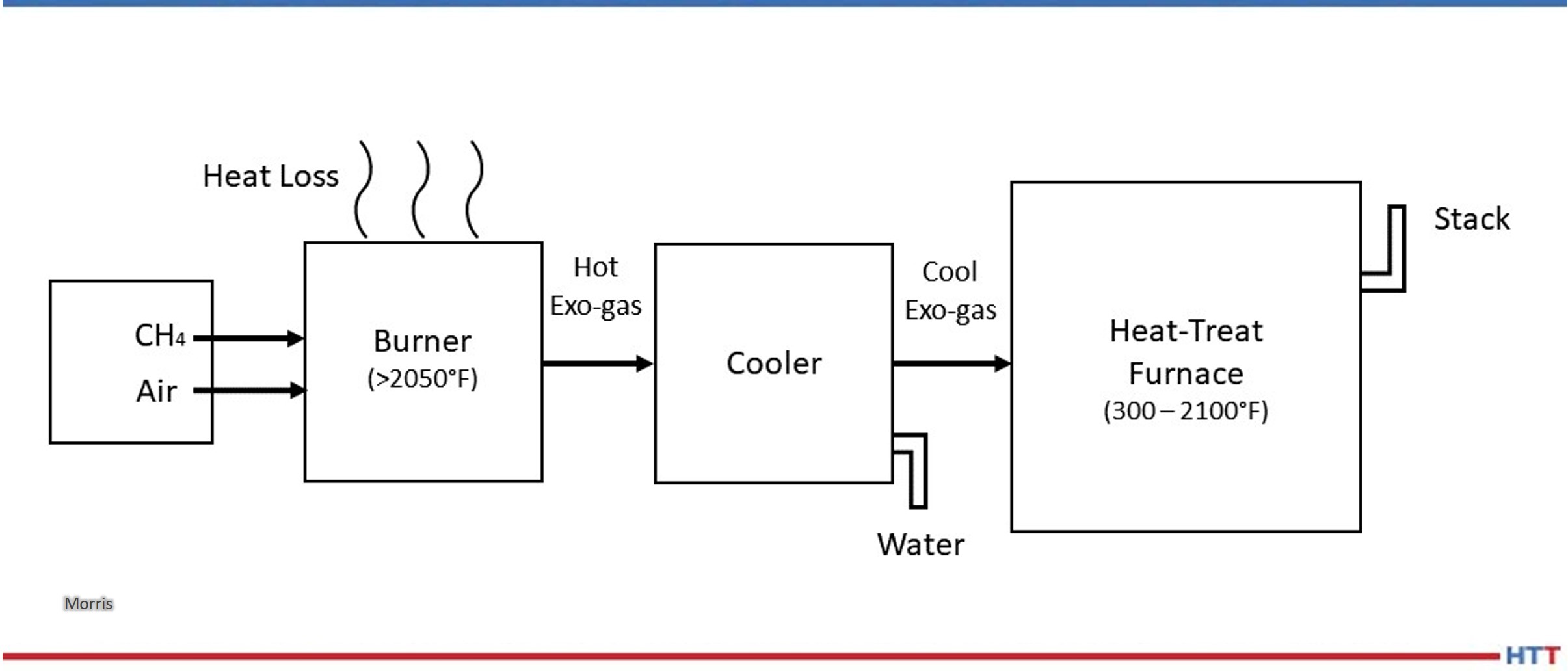
Exothermic gas, more commonly referred to as Exo gas, is produced by partial combustion of hydrocarbon fuels with air in a well-insulated reaction or combustion chamber at temperatures well above 2000°F. Immediately after they exit the combustion chamber, the reaction products are cooled down using water to a temperature below ambient temperature to avoid condensation. The typical dew point of the cooled down Exo gas is about 10°F above the temperature of the water used to cool down. The cooled down Exo is then delivered to the heat treat furnaces where it gets reheated to the operating temperatures between 300°F and 2100°F.
Contact us with your Reader Feedback!
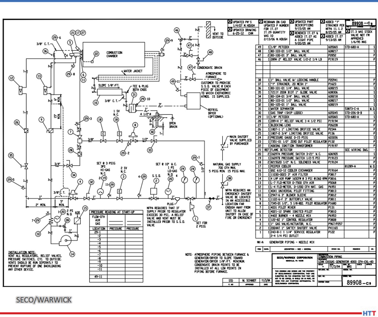
A simplified schematic flow diagram of Exo gas production followed by its cool down below ambient temperature and its final use in heat treat furnaces is shown in Figure 1.
The following aspects of the Exo gas production are clear from Figure 1:
There is lot of energy lost out of the reaction chamber.
There is additional heat lost during cooling using water.
A good deal of water is used for cooling.
The cooled down Exo gas is re-heated to the process temperature in heat treat furnaces.
Exo gas has been predominantly used and is still being used as a source of nitrogen rich atmosphere for purging, blanketing, and mildly oxide reducing applications in the heat treat and metal working industries.
Figure 1. Schematic flow diagram showing Exo production, cool down, and its use.
Source: Morris, “Exothermic Reactions,” 2023
Examples of applications:
Brazing
Annealing
Hardening
Normalizing
Sintering
Tempering, etc.
Examples of materials:
Irons
Steels
Electrical steels
Copper
Copper-base alloys
Aluminum
Jewelry alloys
Examples of product sizes and shapes:
Tubes
Rods
Coils
Sheets
Plates
Components
Small parts, etc.
Exo is the lowest cost gas used in furnaces operating at temperatures above about 700°F to keep air out and provide a protective atmosphere with some oxide reducing potential to the materials being thermally processed.
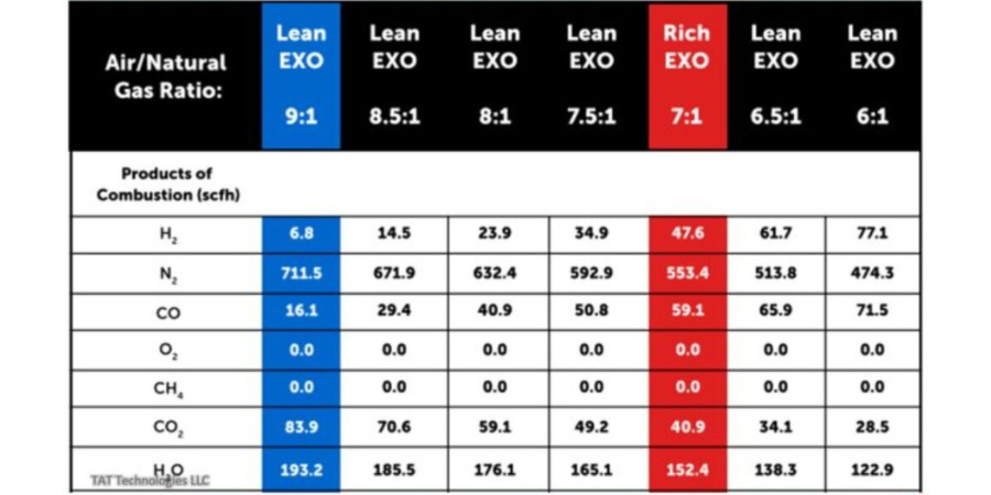
There are two types of Exo gases: lean Exo gas, with mostly nitrogen and carbon dioxide and very little hydrogen, and rich Exo gas, with a little less nitrogen and carbon dioxide and substantially more hydrogen and some carbon monoxide. Typical compositions are given below:
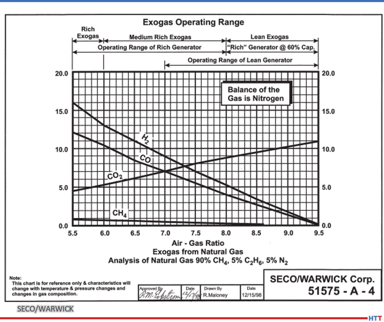
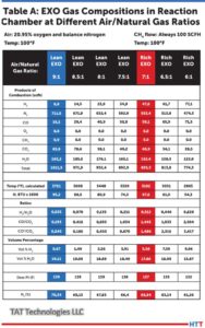
Figure 2. Exo gas operating range
Source: SECO/WARWICK
Figure 2 shows graphs of Exo gas composition at various air to natural gas ratios. H2, CO, and residual CH4 decreases with increasing air to natural gas ratio whereas CO2 goes in the opposite direction. H20 content not shown in the graphs is typically in the 2–4% range depending upon the temperature and cooling efficiency of the cooling system. N2 is the balance which increases with increasing air to natural gas ratio.
The generator designs to produce lean and rich Exo gases are slightly different as shown in the schematic flow diagrams below in Figures 3 and 4.
Objective
This paper will demonstrate a simplified software program (harb-9US) developed recently by TAT Technologies LLC that can easily calculate the reaction products composition, temperature, exothermic energy released, various ratios, and final dew point for various combinations of air and fuel flows entering the reaction chamber at a predetermined temperature and pressure.
The data presented in this paper is under thermodynamically equilibrium conditions only, captured when the reaction is fully completed. It does not tell how long it will take for the reaction to reach completion. However, it can be safely said that reactions are completed relatively fast at temperatures above about 1500°F and very slow at temperatures below about 1000°F. The current software program uses U.S. units: flow in SCFH, pressure in PSIG, temperature in degrees Fahrenheit, and heat as enthalpy in BTU.
The composition of the Exo gas for a fixed incoming air to hydrocarbon fuel ratio changes from production in the combustion chamber to the cool down equipment to bring the Exo gas to below the ambient temperature and finally into the furnace where the material is being heat treated.
Understanding the changes in gas composition from Step 1 (Production in the Combustion Chamber) to Step 2 (Cool Down to Ambient Temperature) to Step 3 (At Temperature of Heat Treated Part) can help to improve the composition, quality, and control of Exo gas that will surround the metallic products being heat treated in the furnace.
Step 1: Composition of Exo Gas as Produced in the Combustion Chamber
Table A shows the Exo gas compositions as generated within the combustion chamber at various air to natural gas ratios supplied at 100°F and 0.1 PSIG. In these calculations natural gas composition is assumed as 100% CH4 and air is assumed as 20.95% oxygen and balance nitrogen. CH4 is fixed at 100 SCFH and air flow is varied to give air to natural gas ratios between 9 and 6. Typically a ratio of 9 is used for lean Exo and 7 is used for rich Exo applications. Other ratios are used in some special applications.
Table A: Exo gas compositions in reaction chamber based on 100 SCFH of CH4 with air 900, 850, 800, 750, 700, 650, and 600 SCFH to give air to natural gas (CH4) ratios of 9, 8.5, 8, 7.5, 7, 6.5 and 6 respectively. Air and natural gas (CH4) are at 100°F before entering the combustion chamber.
Source: TAT Technologies LLC
The following key conclusions can be made from Table A as one moves from air to natural gas (CH4) ratio of 9 down to 6:
The peak temperature in the reaction chambers goes from a high of 3721°F down to low of 2865°F. Because of high temperatures, good insulation around the combustion chamber is a must. A significant portion of the exothermally generated energy within the reaction chamber is lost to the surroundings.
There is no residual CH4 in the Exo gas composition at these high temperatures. There is no soot (carbon residue) under equilibrium conditions.
H20 content in the natural gas (CH4) gas in the reaction chamber is very high — from high of 19.11% to low of 15.87%. These correspond to dew point 139°F to 132°F — well above the ambient temperature. Because of the very high dew point, the Exo gas coming out of the reaction chamber must be cooled down below the ambient temperature to remove most of the H20 in the Exo gas to avoid any condensation in the pipes carrying the Exo gas toward the furnace and into the
furnace.
H2% changes significantly from 0.67% to 9.96%.
The oxide reducing potential (ORP) as measured by H2/H20 ratio changes from a very low of 0.035 to 0.628. ORP in the reaction chamber is overall quite low because of high percentage of H20.
Nitrogen content varies from 70.34% to 61.26% of the total Exo gas in the reaction chamber.
Exothermic heat generated varies from 95.3 MBTU to 54.34 MBTU — it gradually becomes a less exothermic reaction. Gross heating value of CH4 (at full combustion) is 101.1 MBTU/100 cubic foot of CH4.
Question: What happens to the composition of Exo gas as it cools from peak temperature in the combustion chamber to different lower temperatures after it exits from the combustion chamber?
Answer: It changes a LOT, assuming enough time is provided to reach its equilibrium values during cooling down to any specific temperature. Whenever there is a mixture of gases, such as CH4, H2, H20, CO, CO2,O2, N2, there are a variety of reactions going on between the constituents in the reactant gases to produce different combinations of gas products and heats (absorbed or liberated) at different temperatures. The most popular and well-known reactions are:
Partial Oxidation Reaction: CH4+ 1/2O2 → CO + 2H2 — exothermic. The reaction becomes more exothermic as O2 increases from 0.5 to 2.
Water Gas Shift Reaction: CO + H20 → CO2 + H2 — slightly exothermic. It usually takes place at higher temperatures faster. A catalyst in the reaction chamber can help to lower the high temperature requirement. There are many catalysts. Commonly used are either Ni or precious metals.
CO2 Reforming Reaction: CH4 + CO2 → 2CO + 2H2 — endothermic.
All of these reactions have different degrees of influences from changes in temperature. One could say that the final equilibrium composition of the Exo gas is a continuously moving target as temperature changes. Only the N2 portion stays constant. One can make the following generalized statements covering a broad range of Exo gases (lean and rich) in the reaction chamber:
a) N2 content does not change. It remains neutral at all temperatures.
b) H2 content decreases with increasing temperature.
c) H20 (vapor) content increases with increasing temperature.
d) CO content increases with increasing temperature.
e) CO2 content decreases with increasing temperature.
f) Residual CH4 decreases with increasing temperature.
g) Soot decreases with increasing temperature.
h) Catalysts facilitate the speed of reactions at any temperature.
Conclusion
Exo gas composition changes during its time in the combustion chamber. Reaction products composition, temperature, exothermic energy released, various ratios, and final dew point are all items that need to be taken into consideration to protect the metallic pieces that will be heat treated in the resulting atmosphere. Part 2 will demonstrate this principle and discuss Step 2 (Cool Down to Ambient Temperature) and Step 3 (At Temperature of Heat Treated Part).
About the author:
Harb Nayar is the founder and president of TAT Technologies LLC. Harb is both an inquisitive learner and dynamic entrepreneur who will share his current interests in the powder metal industry, and what he anticipates for the future of the industry, especially where it bisects with heat treating
For heat treat operations, use of hydrogen comes with questions about price-point, safety, and storage or delivery. Read this case study to learn how a manufacturer with in-house heat treat, Riverhawk Company, contended with these questions and decided to meet stringent production requirements for pivot bearings by leveraging on-site hydrogen and a hydrogen furnace.
This original content article was written by Marie Pompili, a freelance writer, for Heat Treat Today's May 2023 Sustainable Heat Treat Technologies print edition.
For companies using hydrogen furnaces for heat treating operations, questions always surface surrounding the provision of the necessary hydrogen. Should we have it delivered in cylinders? Do we have the room outdoors for a large storage tank? Can we generate it ourselves? For Randy Gorman, maintenance supervisor at Riverhawk Company, the overriding question is always, “How do we handle hydrogen safely?” The ultimate solution the company chose was the installation of an on-site hydrogen generator. How and why the in-house heat treater came to that conclusion is an interesting story.
Making a History
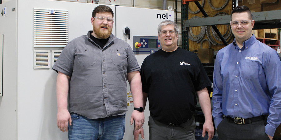
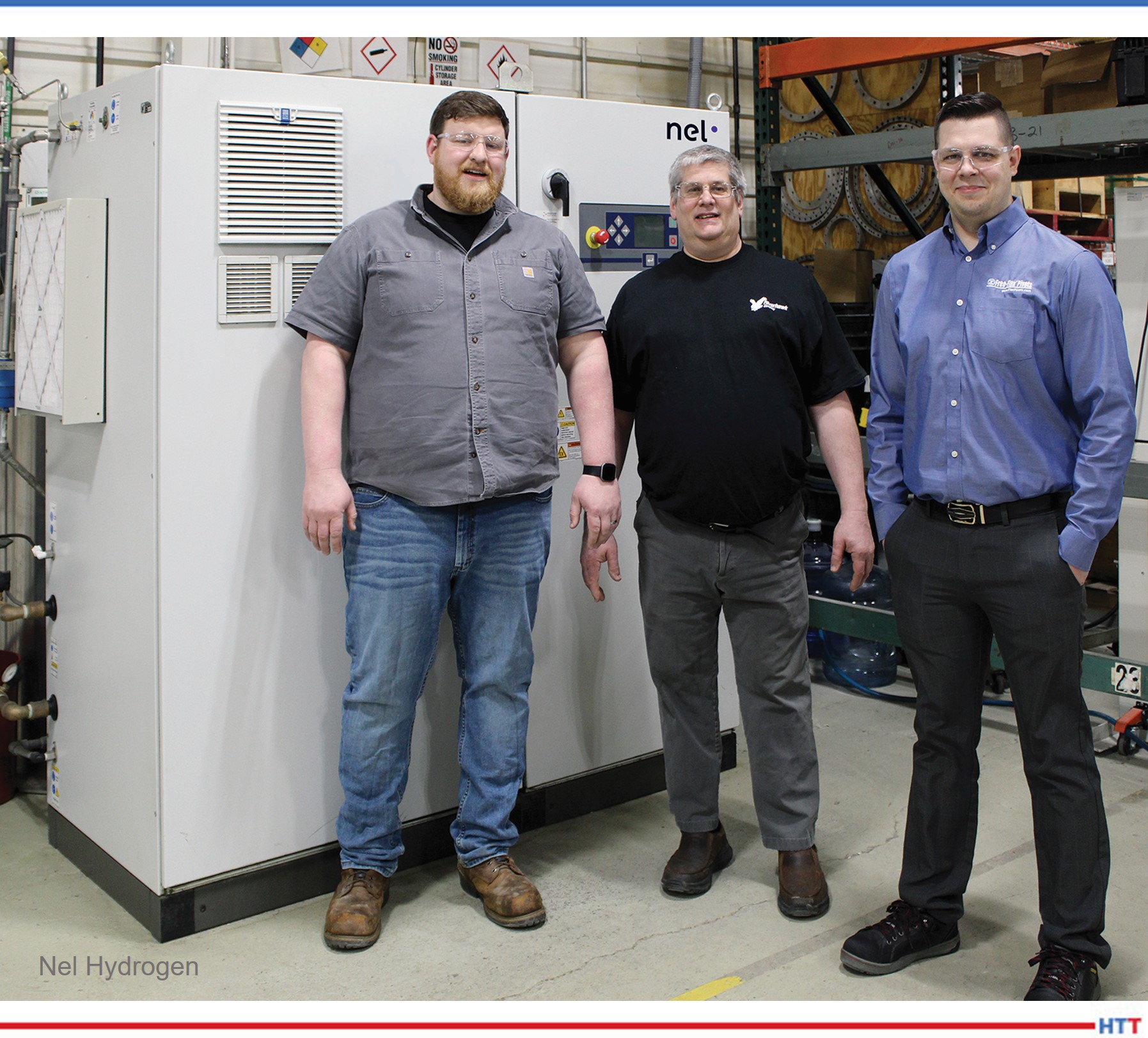
Riverhawk staff (L to R): Spencer Roose, Flex Pivots Manager; Randy Gorman, Maintenance Supervisor; and Josh Suppa, Pivot Department Engineer Source: Nel Hydrogen
Contact us with your Reader Feedback!
Located in New Hartford, NY, Riverhawk Company was established in 1993 as a value-added provider of hydraulic tooling. The company quickly grew from a “buy and assemble” operation to a manufacturer with 14 CNC machine tools, 21 conventional machines, and all the necessary peripheral devices, tools, and software. Through a period of smart acquisitions and the development of new product lines, Riverhawk became one of the leading manufacturers of tensioners, powertrain couplings, and accessories for the turbomachinery industry; the instrumentation product line of legacy torque and vibrations measuring instruments; and the Free- Flex® pivot bearings, which are very well known in high performance industry sectors.
Pivot Bearing Line Requires Improved Heat Treat Abilities
The Free-Flex® pivot bearing line is the focus in this heat treat/hydrogen story. Riverhawk purchased this line from Goodrich in 2004. It is the same product that was developed by Bendix more than 60 years ago. In fact, many of the original part numbers are the same, and the manufacturer strives to maintain the quality and performance characteristics that Bendix established more than six decades ago. Many of the manufacturer’s clients have been purchasing flex pivots for long-running applications, some of which are 25 to 50 years old.
Cantilevered-double ended thick spring. Riverhawk purchased the Free-Flex® pivot bearing line from Goodrich. Many of the company’s clients, in a wide range of critical industries, have been purchasing flex pivots for long-running applications. Source: Nel Hydrogen
If a product line could talk, the flex pivots could share some tales and compelling accounts about all it has seen and done in the world’s most critical and sophisticated applications — many in the military, commercial aerospace, outer space, industrial robotics, medical, clean rooms, information technology, semiconductors, and many more. In all of these challenging sectors, clients are well-known and demand exacting results.
Shortly after integrating the pivot line into its existing production processes, it became clear that the company needed to improve its heat treat function. After researching several options, Riverhawk purchased a new Camco batch hydrogen furnace.
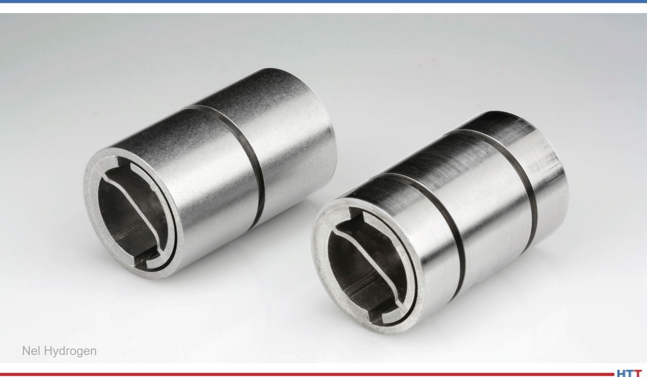
The pivot line consists of flat springs crossed at 90° and supporting cylindrical counter-rotating sleeves. Standard Free-Flex® pivots are made from 410 and 420 stainless steel; however, certain special material compositions include 455 stainless, Inconel 718, titanium, and maraging steel. During the manufacturing process for the flexure bearings, Riverhawk uses the batch atmosphere heat treat furnace to braze the springs to the body halves using a braze alloy, and to simultaneously heat treat certain components in the assembly. The atmosphere used for the heat treating and brazing is a 100% hydrogen atmosphere — chosen because it is universally applicable to all the different metallurgy used for the flex pivots.
The Tension: Delivered vs. On-site Hydrogen?
The use of a batch atmosphere heat treat furnace requires that the hydrogen atmosphere be flushed from the furnace with inert nitrogen when a finished batch is unloaded and a new load is added. Likewise, the furnace must return to inert atmosphere again with nitrogen after the new load is added, and before hydrogen is again injected; hence, hydrogen is used in a batch-wise fashion. The function of the hydrogen atmosphere is to prevent oxidation of the metal surfaces, and to promote fluxing of the braze alloy during the thermal cycle.
Until 2009, Riverhawk used hydrogen-filled cylinders to provide hydrogen to their batch heat treat furnace. Each run of the furnace would use several cylinders of hydrogen. Increases in production rates required careful management of hydrogen gas supply to the furnace. Running out of hydrogen mid-run could sacrifice a whole batch of nearly completed parts.
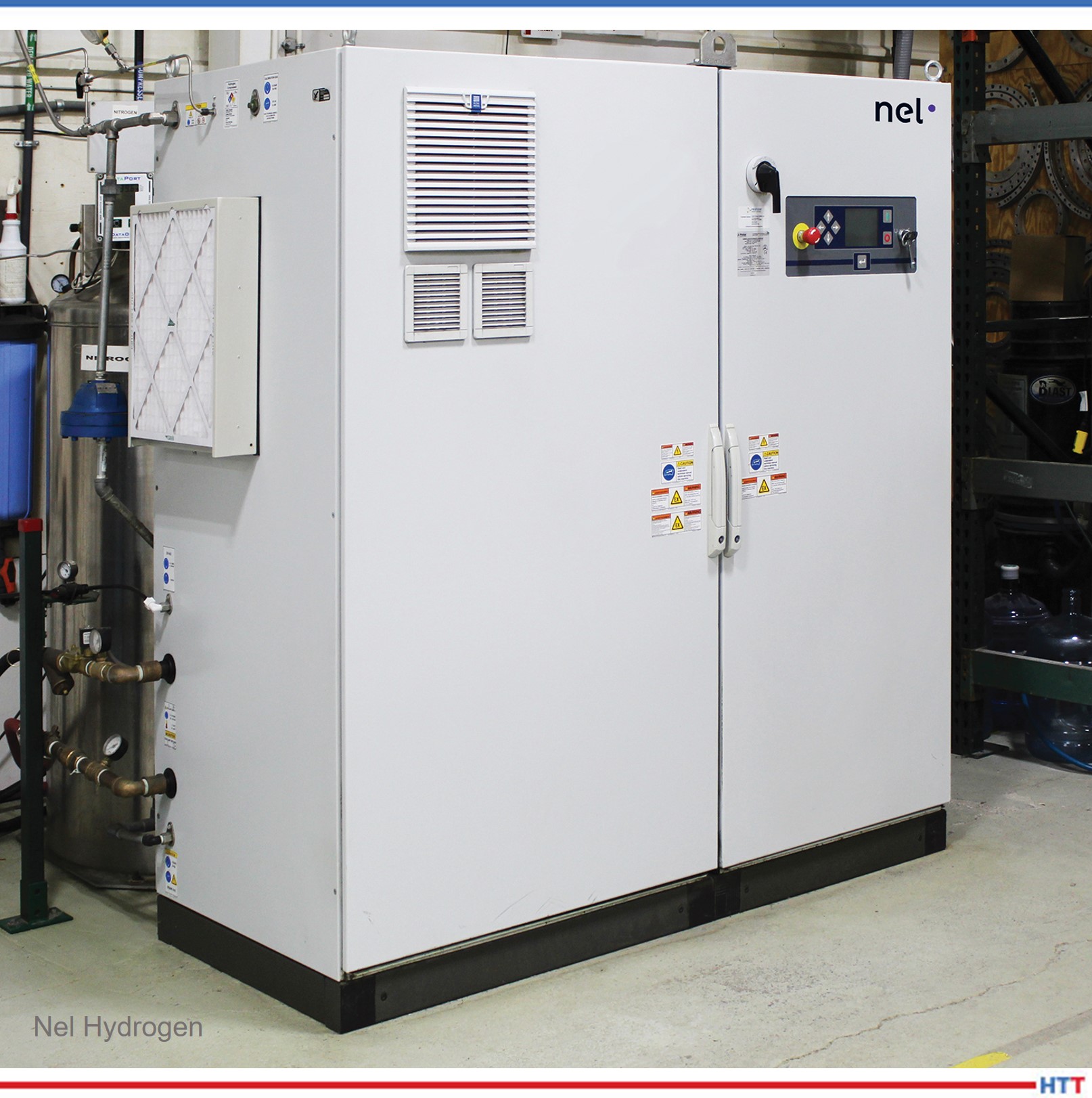
In 2009, the company elected to move away from hydrogen cylinders and transition to a hydrogen supply approach less disruptive to their production process. The choices were either bulk stored hydrogen or on-site hydrogen generation. After extensive consideration, they chose a model H2 hydrogen generator from Nel Hydrogen because the zero-inventory hydrogen generation saved the company money as compared to the cost of permitting, construction, and compliance for bulk stored hydrogen approaches.
The approach that was not chosen — delivered, stored bulk hydrogen — was unappealing for several reasons. Chief among these were the capital cost of the hydrogen storage infrastructure, the requirement for permitting for the necessary hydrogen storage, the accompanying project schedule risk for permitting, the continuous compliance issues with stored hydrogen, and the price volatility of delivered hydrogen that would have made cost accounting more difficult.
“The state and local regulations were likely necessary; however, there was a lot to wade through to become compliant,” said Gorman.
Finding the Best Way
Fast forward 14 years to today and Riverhawk is once again analyzing its approach to handling its hydrogen requirement.
“The H2 model generator that we have has served us well for 14 years, several years beyond the typical life of a cell stack,” said Gorman. “But we need more capacity and redundancy due to the increased demand for our Free-Flex® products and to cost-effectively mitigate the risk of a hydrogen generator issue, leaving us without the use of our furnace.”
The company decided to go with a model H4 hydrogen generator from Nel Hydrogen, which doubles their capacity with two cell stacks and the capacity for three if and when needed. The new system features the same footprint as the former H2 model, which is important to them, and they are even gaining floor space as they will eliminate the number of cylinders formerly stored nearby. The additional free space to move about also appeals to Gorman’s top mandate for safety.
Josh Suppa — engineer of the Pivot Department at Riverhawk — has had hands-on experience with this particular generator series (pictured above). “The maintenance of it is easy, and if there ever is a rare issue, Nel is quick to respond either in person or if it’s something that they can walk us through, they take all the time we need to resolve the matter and get us back online quickly. From a product line and customer satisfaction perspective, we cannot take the risk of our heat treat operation to go down for long. It’s that integral to our success. It’s essential, really, and one of our core competencies.”
Riverhawk will soon use a model H4 hydrogen generator from Nel Hydrogen, which doubles their capacity with two cell stacks and the capacity for three if and when needed. The new system features the same footprint as the former H2 (pictured here). Source: Nel Hydrogen
Choosing On-Site Hydrogen Generation
Looking back on the initial decision to generate on site, one of the important issues that Riverhawk and Nel personnel had to determine was the most cost-effective configuration of the hydrogen generator and ancillaries to supply the hydrogen required for thermal processing. Had the manufacturer used a continuous furnace such as a belt furnace, then the calculations would have been easy, as the flow rate required would have been level and continuous. Instead, the batch furnace required more complex calculation because the hydrogen flow rate varies depending on the stage of the furnace cycle: fast hydrogen flow to fill the furnace, then slow to maintain the atmosphere, then no flow during parts removal and during loading. Additionally, there were many factors that affected the precise furnace cycles employed, including the size of the pivots in each batch, the number of parts loaded, and the specific metallurgy of the flex pivots in the batch. Overall, the cycle times can vary between 6 and 12 hours per batch.
It is important to seek out a knowledgeable hydrogen partner in this endeavor to specify exactly what’s needed, no more and no less. For heat treat applications, users generally would want compact equipment, extreme hydrogen purity, load following, near-instant on and instant off, and considerable hydrogen pressure that make it flexibly suited for a variety of thermal processes.
By combining on-site hydrogen generation with a small amount of in-process hydrogen surge storage if needed, on-site hydrogen generation can be used to meet the needs of batch processes, such as batch furnaces. By carefully choosing generation rate and pressure, and surge storage vessel volume, the process can provide maximum process flexibility while minimizing the amount of hydrogen actually stored.
In practice, client priorities such as minimum hydrogen storage, or lowest system capital cost, or highest degree of expandability, or least amount of space occupied can be met by choosing the specific hydrogen generator capacity and surge storage system employed for any particular production challenge.
In this case study, the optimum solution chosen was based on lowest capital cost and operating cost (including maintenance) while preserving the maximum possible expandability for production increases, and safety. These sound like common reasons and may be yours as well. Success continues at Riverhawk with the arrival of the new H4 generator in the coming weeks.
About the Author: Marie Pompili is a freelance writer and the owner of Gorman Pompili Communications, LLC.
Hydrogen is a reducing gas used in thermal processing atmospheres for brazing, annealing, metal injection molding, metal additive manufacturing, and glass-to-metal and ceramic-to-metal sealing. Recent supply chain issues, safety concerns surrounding storage, and the growing metal additive manufacturing parts market are making on-site generated hydrogen a burgeoning trend among thermal processors.
This article first appeared in Heat Treat Today’s February 2022 Air & Atmosphere Furnace Systems print editionand was written by LynnGorman, a freelance writer.
Reliance on Hydrogen Delivery Can Be Risky
We learned in 2020 that when the pandemic hit, hydrogen gas supply declined, and liquid hydrogen production slowed accordingly.
Hydrogen is a byproduct of refineries processing crude oil, and when demand for gasoline and other crude oil-based products slows, so does hydrogen production. Even as the economy fights back post COVID-19 the long-term trends in crude oil processing are negative because of increasing fleet electrification.
Hydrogen scavenges oxygen, counteracting minor furnace leaks. Photo Credit: Nel Hydrogen
Besides having more control and assurance that hydrogen will be available on demand as needed, there are other benefits to generating hydrogen on site. According to David Wolff, regional manager at Nel Hydrogen, the only raw materials required to produce hydrogen on site are water and electricity, which are among the most reliable of supply chains. “Essentially the hydrogen becomes another utility with little personnel attention required,” he said. “Electricity and water come into a plant in pipes and wires and are highly reliable. Additionally, there are no hydrogen storage tanks taking up a large amount of unusable space.” He added further that electrolyzers produce ultra-pure, extremely dry hydrogen for best processing results; companies can move the electrolyzers if they relocate to another facility; generating hydrogen eliminates the supply interruptions and contract issues; and producing hydrogen reduces costs over time.
Hydrogen cleans part surfaces to enhance processing results. Photo Credit: Nel Hydrogen
For thermal processors, the ultimate priorities for a thriving business are parts and profits. Satisfying customers with high quality, heat treated components keep them coming back. To that end, generating hydrogen on site can play a significant role . For instance, hydrogen has the highest heat transmission of any gas, resulting in faster heating, faster cooling, and faster cycle times in both continuous and batch furnaces. Hydrogen atmospheres clean parts, and clean part surfaces enhance sintering/fusion. Hydrogen also scavenges oxygen which counteracts potential furnace leaks. Companies that make their own pure hydrogen, already formulated for their thermal process atmospheres and always available, can potentially improve plant productivity and part quality with the desired properties demanded by their customers.
“The many positives of hydrogen generation work for companies experiencing environmental pressures to choose alternatives to delivered and stored gases,” said Wolff. For instance, he cited a case in which a specialty wire producer in an urban area used dissociated ammonia for wire annealing for decades. However, a gradual shift in their neighborhood to less industry and more housing, schools, and places of worship made it risky to continue storing the toxic ammonia gas to make dissociated ammonia. The company chose to invest in hydrogen and nitrogen generation to replace their ammonia storage and dissociator. According to Wolff, the company is now using less electricity, and can use a leaner atmosphere blend because hydrogen is drier than dissociated ammonia. They are getting cleaner wire, saving money using less electrical power, and eliminating ammonia purchases and tank rental.
Dave Wolff Regional Sales Manager Nel Hydrogen Photo Credit: Nel Hydrogen
In another case, a different specialty wire producer suffered a catastrophic fire that involved hundreds of hydrogen cylinders stored at their historic facility. The company had to replace the plant. To meet current safety and fire code standards, the decision to generate hydrogen was a great choice to comply with the demands of the local fire marshal. According to Wolff, “Authorities having jurisdiction are some of the best advocates for hydrogen generation versus storage.”
Certain Growing Applications Prefer Generated Hydrogen for Best Part Quality
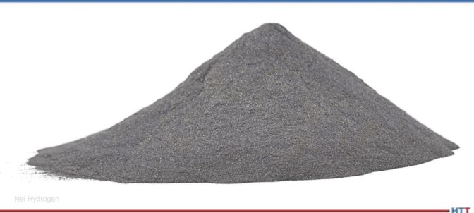
The newest powder-based manufacturing technology is metal AM (metal additive manufacturing) which expands on the learnings and foundations of PM (powder metallurgy) and MIM (metal injection molding). Metal AM is growing rapidly in applicability. Several metal AM techniques are commercialized, and even more are in development. There are several ways that metal AM is revolutionizing fabrication by eliminating complex set-ups, molds, and fixtures, and thereby reducing the costs of short runs. The method allows for continuous design improvements, practically in real time. Metal AM enables parts to be very lightweight through internal strengthening, and parts can be directly translated and produced from a CAD file. In other words, metal AM can create parts that are impossible to make by other approaches. While there is a range of techniques that can be applied to the general category of metal AM parts, most of them use powder, as powder provides the best part finish quality. And, like previous powder fabrication technologies such as PM and MIM, metal AM uses sintering to adhere the metal powder particles together with metal-to-metal bonds.
Metal AM powders are miniscule (20 - 100 microns) and are highly susceptible to oxidation if unprotected by an inert or reducing atmosphere. Photo Credit: Nel Hydrogen
Metal AM powders are miniscule (20–100 microns), uncoated, and handled gently during fabrication. They are highly susceptible to oxidation if unprotected by an appropriate atmosphere. These tiny particles have an enormous surface area (3kg of typical metal AM 316 SS powder has the surface area of a tennis court). Pure hydrogen (or blended with N2 or Ar gas) is the optimal reducing atmosphere for sintering metal AM parts in both atmosphere furnaces and vacuum furnaces. According to Wolff, a company having the capability to produce its own hydrogen will have the best results with these kinds of parts that will grow in demand in the coming years.
Compliance Considerations in Hydrogen Use
While generating hydrogen for on-site use without storing inventory is far safer than storing hydrogen or ammonia, there are still rules to follow. There are issues surrounding exhaust, pressure balancing, air flow, heating/cooling, and other considerations. Safety, of course, is paramount when using hydrogen. Helpful publications to review include NFPA 2, NFPA 55, ASME Code for Pressure Piping B31.1, and FM Global Property Laws Hydrogen Data Sheet. Additionally, if the building is leased, the landlord should be aware of the use of hydrogen as should the insurance agent.
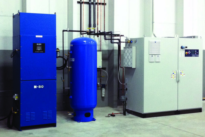
Water electrolyzers are available in a variety of sizes and configurations to meet the hydrogen requirements of any thermal processing facility. Photo Credit: Nel Hydrogen
“Thousands of hydrogen users have proven that, given the right set of circumstances, it’s in their interest and their customers’ interest to generate hydrogen on site,” said Wolff. “And that’s because hydrogen generators produce high purity, pressurized, dry hydrogen with zero hydrogen storage. It’s also a compact, portable, and reliable system, that provides a range of flow rates to suit any thermal processing requirement. And, the hydrogen cost is relatively fixed, so as production goes up, the cost per part goes down.”
Curious about proper gas atmospheres needed to meet high-tolerance standards for additive manufactured parts before, during, and after the heat treating process?
Learn about them in this detailed original content article from Heat TreatToday’sAerospace 2021 print magazine. The author, Lisa Mercando, Ph.D., is the marketing manager of strategic marketing & development at Air Products. You can access the other articles in our digital edition here. Enjoy the Technical Tuesday!
Lisa Mercando, Ph.D. Marketing Manager, Strategic Marketing & Development Air Products
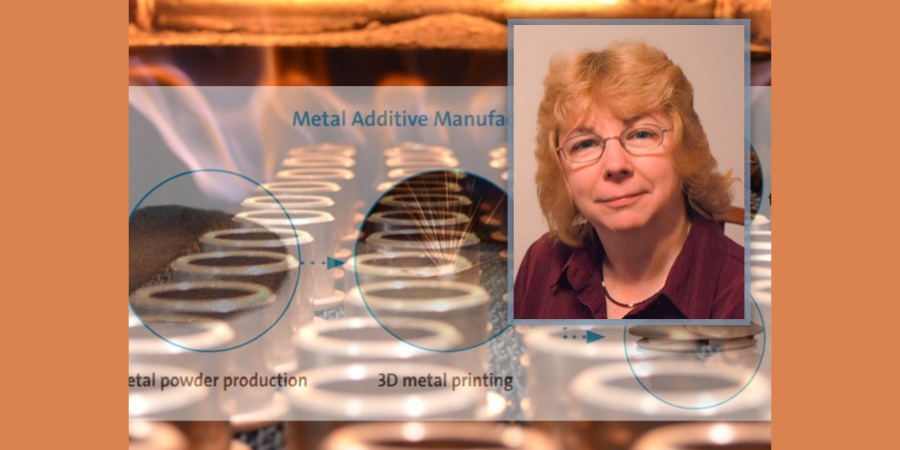
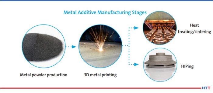
In a world of rapid prototyping and production of metal components, it is imperative to have the proper gas atmosphere to produce quality parts. Argon, nitrogen, and helium are commonly used to create inert atmospheres in order to meet the high-tolerance standards required for additive manufactured (AM) aerospace parts. Industrial gases are used every step of the way from powder production to various additive manufacturing techniques to finishing processes that include heat treating and hot isostatic pressing (HIPing).
Inert gas atomization is the best method to obtain dense, spherical particles, which are best for AM applications where the desired particle size is usually less than 100 microns. Additionally, inert gas atomization greatly reduces risk for oxidation, providing a high level of powder purity and quality. Helium provides the best results when its superior heat transfer capabilities are needed. This process achieves the following properties: dense and spherical particles; high quality and purity metal powders; and narrow particle size distribution. We can provide high pressure gases for powder atomization and hydrogen-based atmospheres for powder reduction and annealing.
Image demonstrating metal additive manufacturing
To meet the high-tolerance standards required in additive manufacturing–particularly for aerospace–nitrogen and argon are commonly used to provide inert atmospheres. The use of helium, with its high thermal conductivity, offers an interesting option for minimizing the thermal distortion of elongated parts during printing. An inert atmosphere provides numerous benefits on a printed part by:
reducing oxidation of printed parts by lowering the oxygen concentration in the build chamber
improving safety through the inerting of combustible dust during powder handling and sieving
creating a stable printing environment by maintaining constant pressure in the print chamber
mitigating powder clumping in the feed tube
preventing part deformation by controlling thermal stress through effective cooling
Gas requirements differ based on the process being used and the material being printed.
Often, AM aerospace parts require additional processing to achieve the desired final properties. This is done mainly in the form of heat treating, sintering, or HIPing. All three processes have industrial gas requirements for preventing oxidation. Heat treating with argon, nitrogen, hydrogen, or a nitrogen/hydrogen blend can relieve internal stresses and enhance part properties such as strength, ductility, and hardness. In sintering applications, nitrogen/hydrogen blends or argon/hydrogen blends are important in producing near-net shape parts with increased strength and uniformity. High pressure argon is used in HIPing applications to provide fully dense parts with increased strength and reliability.
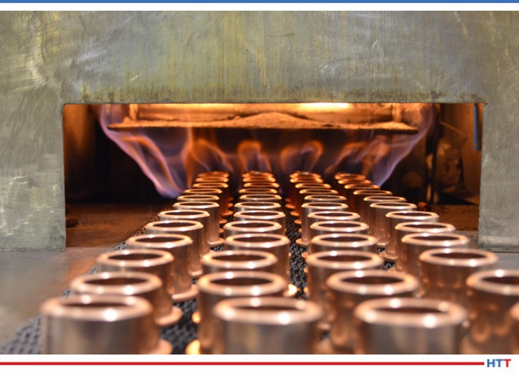
Image of a furnace heating metal parts
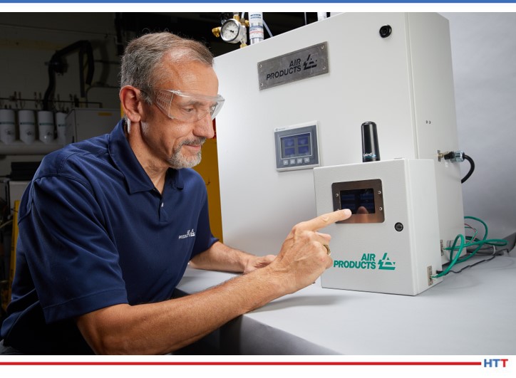
In addition to providing the bulk industrial gases required, the company has developed state-of-the-art process intelligence systems. These systems monitor atmosphere composition parameters to ensure the process is running with the desired gas atmospheres and provide alerts for any needed maintenance or adjustments. Decades of metals processing experience in gas supply, applications, process knowledge, and safety are applied to help improve heat treating efficiency and part quality.
Remote tank monitoring is one example of the company’s Process Intelligence™. Operators increasingly rely on data to closely track critical process parameters, such as the use and inventory of vital industrial gases. This tank monitoring system enables operators to remotely check their supply levels and monitor usage from a touch screen in the plant, on their laptop, or on their mobile device. Customized daily reports are a common way to stay current on their industrial gas supply.
For heat treatment operations using a furnace atmosphere that is flammable or potentially flammable, an inert purge gas – typically nitrogen – is utilized to help ensure safe operation. This system alerts operators to the condition of the liquid nitrogen supply and helps them remotely track their supply and usage of gases. Optional system alarms allow operators to safely initiate a controlled purge shutdown, enabling compliance with NFPA 86 by confirming they have adequate liquid storage levels, or ensuring their nitrogen piping temperature remains at a safe level. Typically installed near the furnace operation, the remote touch screen on the base station displays conditions of all bulk gas storage tanks and can use both audible and visual alarms to warn the operator of a potentially critical situation.
Tank Monitoring
In addition to using inert gases, such as nitrogen and argon for the 3D printing processes, GE Additive Manufacturing, located in Cincinnati, OH and a major manufacturing center for additive manufacturing, also performs post processing heat treatment/sintering on the metal parts to enhance part quality. Their capabilities allow for the production of quick, precise parts with high levels of accuracy, even on intricate shapes and geometries across multiple applications.
Conclusion
If you are prototyping and producing metal components, be sure to consider the importance of achieving the optimum gas atmosphere to efficiently make quality parts. The heat treat postprocessing of AM metal parts is often required to produce the high-quality parts specified for the aerospace industry.
About the Author: Dr. Lisa Mercando is the marketing manager, Strategic Marketing & Development, for Air Products’ metals processing industry. She has worked at Air Products for 28 years in a variety of roles and responsibilities and is the author of several patents and technical articles.
One of the great benefits of a community of heat treaters is the opportunity to challenge old habits and look at new ways of doing things. Heat TreatToday’s101 Heat TreatTipsis another opportunity to learn the tips, tricks, and hacks shared by some of the industry’s foremost experts.
Today’s tips come to us from Nel Hydrogen covering atmospheric solutions and Wisconsin Oven Corporation with a tip on gas chamber issues. Additionally, Pelican Wire provides 4 quick tips on Thermocouples.
Heat TreatToday welcomes you to submit your own heat treat tip for Heat TreatToday's 2020 Fall issue to benefit your industry colleagues. You can submit your tip(s) to karen@heattreattoday.com or editor@heattreattoday.com.
Heat TreatTip #11
Compliance Issues? Try On-Site Gas Generation
On-site gas generation may help resolve compliance issues. Growth and success in thermal processing may have resulted in you expanding your inventory of reducing atmosphere gases. If you are storing hydrogen or ammonia for Dissociated Ammonia (DA), both of which are classed by the EPA as Highly Hazardous Materials, expanding gas inventory can create compliance issues. It is now possible to create reducing gas atmospheres on a make-it-as-you-use-it basis, minimizing site inventory of hazardous materials and facilitating growth while ensuring HazMat compliance. Modern hydrogen generators can serve small and large flow rates, can load follow, and can make unlimited hydrogen volumes with virtually zero stored HazMat inventory. Hydrogen is the key reducing constituent in both blended hydrogen-nitrogen and DA atmospheres—hydrogen generation (and optionally, nitrogen generation) can be used to provide exactly the atmosphere required but with zero hazardous material storage and at a predictable, economical cost. (Nel Hydrogen)
Generate H2 and N2 on-site – saving money, improving safety, and reducing carbon footprint.
Heat TreatTip #12
Oven Chamber Failing the Test? Try This!
When having difficulties passing a temperature uniformity test, check the pressure of the heating chamber. This can be done with a pressure gauge that reads inches of water pressure. The best uniformity is achieved when the pressure is neutral or slightly positive (0” to +.25” wc). If the pressure is negative (even slightly), it can draw a stream of outside cold air into the chamber, causing cold spots. For the best results and ease of analysis, permanently mount a gauge to read the pressure. Any issues with pressure can be easily recognized and corrected. (Wisconsin Oven Corporation)
Heat TreatTip #70
Type N Thermocouple (Nicrosil / Nisil)
Type N Thermocouple (Nicrosil/Nisil): The Type N shares the same accuracy and temperature limits as the Type K. Type N is slightly more expensive and has better repeatability between 572°F to 932°F (300°C to 500°C) compared to Type K. (Pelican Wire)
Heat TreatTip #71
Know Your Thermocouple Wire Insulations
Know your thermocouple wire insulations. When is Teflon® not Teflon®? Teflon® is a brand name for PTFE or Polytetrafluoroethylene owned by Chemours, a spin-off from Dupont. FEP is Fluorinated Ethylene Propylene. PFA is Perfluoroalkoxy Polymer. All three are part of the Fluoropolymer family but have different properties. Of the three compounds, PTFE has the highest heat resistance, PFA second highest and FEP third. The higher the heat resistance the more expensive the insulation. Keep that in mind when specifying the insulation and only pay for what you need. (Pelican Wire)
Heat TreatTip #72
Resistance Temperature Detectors (RTDs)
Resistance Temperature Detectors (RTDs) are replacing thermocouples in applications below 1112°F (600°C) due to higher accuracy and repeatability. Typical constructions are multiconductor cables with nickel-plated copper conductors. (Pelican Wire)
Heat TreatTip #74
When to Use Type K Thermocouples
Type K thermocouples should only be used with the appropriate Type K thermocouple wire. Type K measures a very wide temperature range, making it popular in many industries including heat treating. An added benefit with Type K is that it can be used with grounded probes, ungrounded probes, and exposed or uncoated wire probes which are attached to the probe wall, measure without penetration, and have a quick response time respectively. (Pelican Wire)
Heat TreatTip #100
The Right Furnace Atmospheres Will Pay Dividends
Precision blended gas system provides the atmosphere needed at the most economical cost.
Save money on your furnace atmospheres by employing the driest and leanest furnace atmosphere blends possible. Furnace atmospheres are a compromise between keeping it simple and supplying exactly the atmosphere to meet the unique requirements of each material processed. Organizations have different priorities when it comes to atmospheres—heat treat specialists may want to be able to run as many different materials as possible using a limited array of atmosphere types, while captive heat treating operations often want exactly the atmosphere approach to maximize the benefits for their specific processes/products.
The dewpoint (water content) of the atmosphere in the furnace is a key factor in its performance. At high temperatures, water in the atmosphere can break down, releasing oxygen that can cause oxidation. You must maintain a high degree of reducing potential to achieve the surface finish and processing results desired. If the furnace atmosphere gas is wet, you’ll need a gas blend richer with hydrogen than you would if your atmosphere blend had a lower dewpoint (less water vapor content). Since hydrogen costs 10 times more than nitrogen, it is more economical to run a leaner atmosphere than a richer atmosphere. By running the driest atmosphere blend possible, you may find that you can lean down your atmosphere (consistent with the metallurgical needs of your product/process) by reducing the proportion of hydrogen and increasing the nitrogen. In doing so, you may recognize meaningful savings.
Check your furnace atmosphere raw materials and process and obtain the driest atmosphere possible. Control your atmosphere dewpoint by adding humidity as needed to the driest starting blend possible rather than accepting a wet atmosphere and trying to process your parts. You’ll achieve the best compromise of excellent results at the lowest cost. (Nel Hydrogen)