Heat Treat Radio #134: Optimizing Power Delivery in Thermal Processing
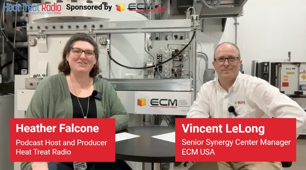
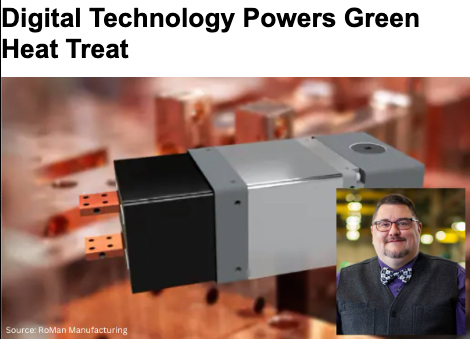
In this episode of Heat Treat Radio, host Heather Falcone sits down with Casey O’Neill, vice president of Sales and Marketing at RoMan Manufacturing, to discuss a holistic approach to energy efficiency in thermal processing. Casey explains how furnace power systems, transformer placement, electrification strategies, and data-driven monitoring can significantly impact operating costs, maintenance requirements, and overall performance. The conversation also explores how emerging technologies such as digital twins and AI-driven analytics may help heat treaters address workforce challenges while improving energy management and productivity.
Below, you can watch the video, listen to the podcast by clicking on the audio play button, or read an edited transcript.


The following transcript has been edited for your reading enjoyment.
Introduction (00:04)
Heather Falcone: Hi, I’m Heather Falcone. Welcome to Heat Treat Radio.
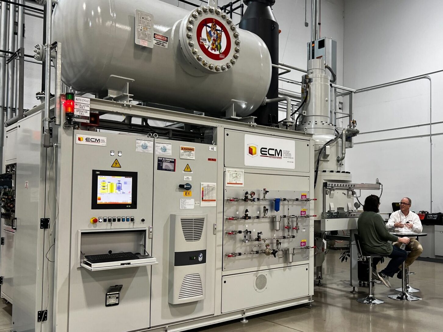
Today we’re talking about holistic solutions to thermal processing system energy efficiency. We’re on-site with the sponsor of today’s episode, RoMan Manufacturing, in Wyoming, Michigan. We had the opportunity to take a tour before recording, so thank you to RoMan for hosting us. Joining me today is Casey O’Neill, vice president of Sales and Marketing. Thanks for joining me today, Casey.
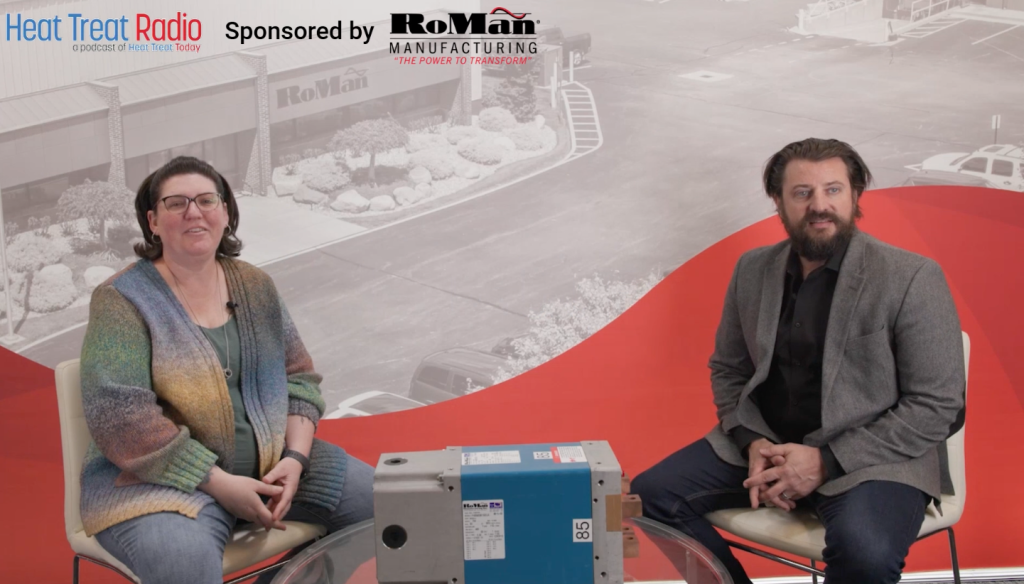
Casey O’Neill: Thank you for being here. We’re excited to host you and record this on the RoMan campus.
Heather Falcone: You get the whole episode to talk about energy efficiency, but I’d like to start by having you tell us a little about yourself and your background. Since we’re at your facility, you get to do your own introduction and tell us a little about RoMan.
Casey O’Neill: I’m Casey O’Neill, vice president of Sales and Marketing at RoMan Manufacturing. I’ve been with RoMan for a number of years, and where I actually started working at RoMan was selling our products into the furnace market.
This segment of industry is really near and dear to my heart. It’s where I got my start in the business. I’m really excited to be able to discuss all the ways that RoMan Manufacturing specifically works to improve the efficiency of electrically heated furnaces within the heat treating industry and how we can help heat treaters money, while improving operational efficiency.
Heather Falcone: I think there are a lot of misconceptions about what can actually be done with energy efficiency. I’d love to dispel some of those myths and help educate people so that making changes to an energy system does not seem so intimidating.
Casey O’Neill: Absolutely. RoMan has a strong history in a variety of different industries, which allows us to take lessons that we’ve learned from one industry and apply them to other industries where that knowledge may not be understood yet.
That’s what we’ve been working to do within the furnace segment is apply our understanding of power and efficiency and how they relate to each other on different pieces of equipment and introduce those to improve the operations of heat treating companies.
Company History (2:53)
Heather Falcone: That’s really how the company got started, right?
Casey O’Neill: Correct. RoMan was founded in 1980 by Dietrich Roth and Robert Hoffman. Dietrich was a brilliant engineer in the power transformation space. His focus was on optimizing power density in a resistance welding transformer.
He developed ways to create the power that was needed in a more compact box. As RoMan has evolved over the last 46 years, we’ve taken that concept and technology and expanded it across the products that we offer different industries.
RoMan supplies products for resistance welding, which is where the company started. We also provide power supplies for glass manufacturing, heat treating furnaces, sintering furnaces, and crystal growing furnaces. Outside of thermal processing, we develop power supplies for specialized projects that require high current. One of RoMan’s strengths is rectifying high-current AC power into high-current DC power.
The expertise needed to do that is fairly limited globally. So, we take on very specialized projects for the government and large primes to put that technology into practice for their applications.
Electrification Trends (4:58)
Casey O’Neill: As it relates to heat treating furnaces, over the last five years, there’s been a significant shift toward electrically heated furnaces. In some cases, companies are looking at converting gas-fired furnaces to electrically heated furnaces. A large part of this trend has to do with broader global electrification initiatives and decarbonization goals. As more and more furnaces are electrified and as more people are looking to buy electrically heated furnaces, our goal is to ensure this industry understands how to optimize that electric power so that the energy is being used by the furnace and not just burning into the air.
Water-Cooled Transformers (6:05)
Heather Falcone: When we talk about energy efficiency and thermal processing, beyond heat loss and leakage, what are the biggest inefficiencies that you’re seeing in heat treat operations today?
Casey O’Neill: From RoMan’s perspective, our core product is high-current, low-voltage, water-cooled transformers. We also integrate those power devices into power systems, like controls, breakers, PLCs, and communication with the main control system.
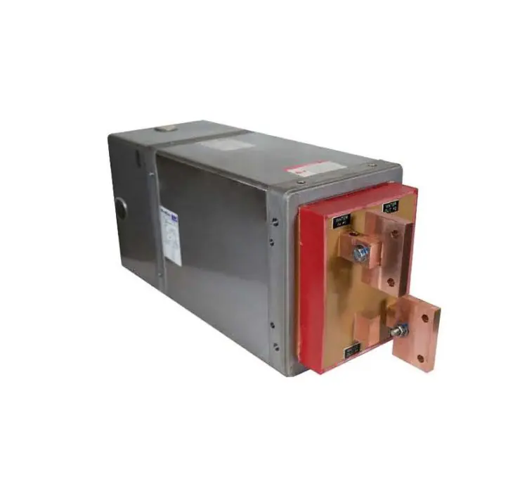
One of the key features is water cooling. In a lot of industries, there are applications where having a water-cooled transformer device is going to make the system more optimized than an air-cooled transformer would. While going to an air-cooled transformer may have a lower upfront cost, if you look at the total cost of ownership versus a power supply that integrates RoMan water-cooled device, because of the equipment optimizations, that will save money on energy and maintenance in the long run. RoMan builds our transformers in a way that integrates the water cooling right into the circuit of the transformer, creating a low-profile, high-power density product. The transformers are fully potted and completely sealed off from the elements. Like I said, we used to test our transformers by submerging them in a fish tank and powering them up to show that water could not get into the transformer and short it out. This allows the transformer to not have to be in a box, so it can be mounted on any equipment, because as long as you’re running the cooling water through the transformer, it’s not going to overheat. It’s impervious to any of the outside elements that you would normally put a different type of transformer in a box for. This allows the transformer to be mounted very close to a power feed-through of a furnace.
Mounting the transformer in this way has many advantages. The secondary side of a transformer, the output side, is the high-current side of the furnace, and the high-current side of an electric circuit is the drastically more inefficient side of the electric circuit because current is heat.
On the primary side, it’s going to be higher voltage and lower current, but when you’re stepping down the voltage and stepping up the current, which is what you do in a transformer on a resistance-heated furnace, you’re creating a high-current, low-voltage secondary.
Well, high current is high heat. If you’re running high-current through big secondary cables from the transformer to the furnace, every foot of that cable is generating heat and wasting energy. So, you’re paying for energy that’s just going into the air.
Heather Falcone: And you’re heating the whole plant at the same time for nothing.
Casey O’Neill: Exactly. You then either have uncomfortable employees, or you need to get a bigger air conditioner.
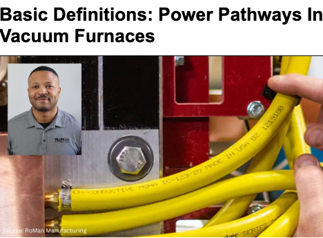
What RoMan is working to integrate into this industry is remote mounting of transformers directly next to or close-coupled to the power feed-through of the furnace. By doing that, you’re eliminating the secondary cables altogether.
Not only does that save you energy losses in those cables, but those cables are also water-cooled, so you eliminate having to water-cool the cables. If they are air-cooled, and then they’re kicking heat off into the building. They’re also a large maintenance item and can be difficult to handle.
I’ve been to many different heat treating facilities, and I’ve talked with operators about integrating RoMan transformers where you’re closely coupling them to the power feeders and eliminating the cables. One of the operators joked with me and said he’d be my best friend forever if we could eliminate all those cables because of how difficult they are to do maintenance on. When you have a cable fail, it must be removed and replaced. RoMan is trying to eliminate those cables and mount this transformer right next to the power feed-through, making it more efficient and easier to maintain. We can do this because we’ve created a high-power, low-profile density transformer, that is impervious to elements; it can be outside of a box and mounted right next to the furnace.
Heather Falcone: That makes sense. When you’re looking for a system, you’re looking for something that decreases that, the past of least resistance, right? Faster, quicker, and easier.
Workforce Challenges (12:14)
Heather Falcone: The population of working people is shrinking, and in the next 10 years, it’s going to be the lowest it’s ever been. As such, it’s going to get harder to find and hire maintenance personnel, furnace operators, and electrical technicians. If companies eliminate that problem entirely, it’s a win-win.
Casey O’Neill: Exactly. One of the biggest challenges I see in the near-term future is a massive loss of knowledge base.
Across the heat treating industry, there are incredibly knowledgeable and experienced people that have kept heat treating companies running for the last 50 years that are approaching retirement.
As they leave the workforce, that knowledge base is not easily replaced. It’s quickly becoming one of the major challenges of not just heat treating but every industry.
Adoption of New Furnace Technology (13:30)
Casey O’Neill: At RoMan, our core product is high-current, low-voltage, water-cooled transformers, but we are also integrating some of this core product into broader power systems. As we start to integrate, we are also trying to create enough data feedback. We can monitor current, voltage, resistance values, and other parameters. With digital controls, that data can be extrapolated and fed back into the furnace system.
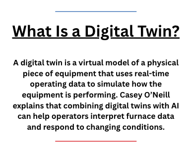
This is where we get into some fun technology. There are companies that can create a digital twin of a piece of equipment by engaging with the equipment and component manufacturers and the OEMs to understand how all of it behaves together.
If we see the transformer temperature internally rising, what does that mean or what could be causing that? If we see a certain part of the furnace inside getting a lot hotter, there are thermocouples inside reading the temperature.
They create a digital twin, and by integrating artificial intelligence, it can start to run simulations in real time, which allows them to communicate next steps with the operator based on what they are seeing with their simulations. So, as experienced personnel enter retirement, we’re going to need to start integrating more of this type of technology into systems or these systems will not operate as well as they should, which means productivity will decrease significantly.
One of the things that RoMan is actively pursuing is determining what feedback our power system can provide to the overall furnace system that’s going to feed into this digital twin and AI simulation to ensure that the furnace can continue to operate in a high productivity fashion, while simultaneously eliminating the challenge of our aging knowledge base.
Heather Falcone: Right. When you’re undertaking a project like energy efficiency, our tendency might be to focus just on that piece of equipment, and we may miss the opportunity to look at the larger picture and incorporate every piece of equipment.
Casey O’Neill: Exactly. As electrification of heat treating furnaces continues, the operational expense of electricity becomes one of the biggest expenses for heat treat operations. So, managing electric consumption has to become one of the most critical issues to address in order to be profitable.
At RoMan, we don’t just try to sell our products, we try to really engage with the users of our products in every industry that we work in so that they understand from our side how to most efficiently use our products in their system as a way to help the overall OPEX of electricity in a heat treating company, keeping it as minimal as possible or at least as efficient as possible. That way, they are only paying for electricity that is actually used to heat treat products and not paying to kick off energy into the air.
Heather Falcone: Let’s talk a little bit about that whole process that you’ve come up with, because many heat treaters are working with legacy systems. It can seem daunting to go from a VRT to this solution. What do you recommend for how they can attack this issue without being intimidated and rejecting the project entirely?
Casey O’Neill: In a number of industries that we work with, this fear is common. Nobody wants to be first. Everybody wants to be second. If we have new technology, they don’t necessarily want to be the first one to be innovative and integrate it into their system because they also don’t want to be the reason that production goes down if it fails.
So, you have systems with legacy products that have been working for decades and that makes people very comfortable with that system. Even if we can make drastic improvements on the overall operational expense, they are motivated by job security, so they want to work with products and technology they feel comfortable with.
We engage with both small and large captive and commercial heat treaters, and what I found is when you engage with a company that has a group that’s really focused on energy efficiency, especially as electrification grows, those people end up having a lot more say in what technology ends up being integrated into a system.
RoMan has a number of systems integrated into heat treating furnaces, and within our product offerings we have different types of power systems used in various applications. We have air-cooled transformers manufactured at our facility in Grand Haven, Michigan, and we have our high-current, low-voltage water-cooled transformers that are 60 hertz, 480-volt input, very basic, that are integrated into different furnace systems.
Our legacy began in resistance welding in the automotive world. If you’ve ever seen the commercials for vehicle manufacturers where you have the metal frame of a car going down an assembly line with robotic arms moving around, sparks flying — that’s resistance welding. It’s a bad example because when you’re doing the welds, you don’t want sparks, but sparks are good for TV.
That’s a resistance weld. On that robot is a weld gun, and in that weld gun is likely (if it’s in North America) a very small RoMan transformer. The input into that transformer is 1,000 hertz, 620 volts, and it’s coming from an IGBT control. In that industry, in the late ’80s/early ’90s, they started to go from larger stationary spot-welding stations to this robotic welding. They’re putting thousands of amps through that little weld gun, and if they were to use an AC transformer, it would be large, and then they would be running those big heavy cables to the weld gun. Also, robots move around so much, so you end up having a lot of maintenance issues and inefficiencies.
By integrating this IGBT control that can put out 1,000 hertz, you can exponentially shrink the core of the transformer, which makes the transformer size shrink significantly. Now since the ’90s, almost every automotive line is using an IGBT control and a really small, high-current, low-voltage, water-cooled transformer that’s in the weld gun connected to where the weld tips are.
RoMan takes something that’s been used for 40 years in one industry and realized there were many applications that would benefit from integrating this type of technology onto a furnace. When you’re running continuous heat for a long time, you end up creating a lot of inefficiencies, which can get really technical.
This system overcomes many inefficiencies using these different types of technology that all look different from what people are used to seeing. What we are trying to do is educate people on the uses of these new technologies and the benefits of their integration on furnaces, particularly the improvement of operational expenses, electrical efficiencies, and also maintenance.
Furnace Integration — Retrofits (24:24)
Heather Falcone: We have discussed RoMan and the systems. Tell me about integration at the furnace level.
Casey O’Neill: As I have mentioned, we have different furnace applications that use different versions of our technology. For commercial heat treaters, heat treating is how they make money, managing operational expenses of the equipment is absolutely critical to profitability.
We have conducted several trials and product integrations where we’ve worked directly with heat treaters to retrofit equipment so they can start to understand and see the operational gains from using our products.

In one case, we had a commercial heat treater that had a vacuum furnace with a large legacy power supply. We have some different data loggers that measure and log power data. We hooked them up to a power logger, and had them operate normally, run different parts that they normally run through that furnace, and we just logged the power data, the kVA, kW, the reactive power, and the power factor — parameters that matter when it comes to power and what the utility companies bill people for. Then we examined that data, and we saw that the power supply that they had for the work that they were doing was oversized.
One of the changes that we could make to optimize the operation of the power supply was to size it more according to their needs. In this case, we retrofitted that furnace with an IGBT control and our small MFDC transformer. We sized the kVA down more to their needs to add some efficiency to the system.
We had them turn it back on and operate normally, using the same parts. We logged the power again and we were able to compare the different runs. We also had them run a burnout run so we could compare the burnouts. As we were doing that, we noticed one run that they were doing after we retrofitted the furnace that wasn’t in any of the logs from before we retrofitted it. We did not know where it came from. The company explained that there is a certain part that they heat treat for a customer and that particular process has a very, very fast ramp rate to get to a very high temperature. In their facility, they only have one furnace that they can do that particular cycle on. After we retrofitted this furnace, they decided to try this particular process, and they were able to do it.
Heather Falcone: That’s awesome.
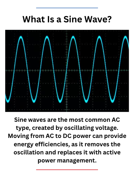
Casey O’Neill: Keep in mind; this was actually a smaller kVA transformer than what was on that furnace before. The output of this transformer is DC, not AC, and AC has a sine wave, which kind of goes like that, and there’s a zero point where it’s always crossing zero. Every time it crosses zero, it’s off for just a little bit. We’re talking milliseconds. But then it has to reheat a little bit. It continues heating, and then it’s off as it crosses zero again.
The MFDC, however, is DC power. DC power is just on, so you’re just managing how much it’s on. As a result, you never have to do that little reheat before you continue heating like you do with AC power.
The best explanation, and this is anecdotal, not data-driven, is when they retrofitted that furnace with DC power, because that DC can just stay on, they were able to ramp much faster and hotter. Even though it was a lower kVA transformer, it still had enough power to get up to temperature. Also, because of the DC power, it was a much better heat, so it could get up to temperature much faster and allow them to do that cycle.
So operationally, they’re now able to run that particular process in two furnaces instead of one. Double the capacity, which is now optimized for a commercial heat treater to be able to shift things around more and have some options when they’re in production.
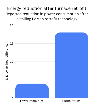
A burnout run is obviously a lot more power than a different run that’s lower temperature or a shorter period of time. On some of those lower temperature runs, there was about a 4% kilowatt hour difference in consumption after we retrofitted it. For the burnout run, the kilowatt hour difference was actually 18%. By retrofitting, it reduced the real power consumption by 18% on every burnout.
The ability to use DC in a resistance application is always going to make it more efficient. But then also by shortening the secondary, you’re eliminating energy waste, optimizing efficiency, and enhancing maintenance.
In that facility, about half of the furnaces now have that IGBT system and these small MFDC transformers. This is a more expensive system. When you look at the total cost of ownership, you have to weigh the costs, is the value there or not? There are certain cases where it is, and there are certain cases where it is not. As I mentioned, half of their furnaces have this system, and the other half do not. That’s because for half of them, there isn’t enough added value to make this change. But for other furnaces at other heat treating companies, we have AC high-current, low-voltage water-cooled transformers like this where those are integrated. We’ve closely mounted them to the power feed-through, and just by getting rid of those secondary cables, we’ve helped improve the efficiency of the furnace. That one is actually really easy to do the math on savings because different size cables have ratings of heat loss per foot. You can easily do the math. On every foot of cable we eliminate; you’re going to save this much in energy consumption.
In some other cases, the transformer, while important, actually becomes less important than the power control. In some commercial heat treaters and in many captive heat treaters, they may run one part over and over and over again. But they have to make sure that every single time it is done exactly the same. We integrate our transformers into a power system where we’re getting controls and other feedback devices that we integrate into the whole system so you can start to monitor and digitally send all that information into a main equipment PLC, which means they can make a lot more informed decisions on how to manage the equipment to ensure that the output is consistent time and time again.
Heather Falcone: Absolutely. I think that’s important to insert in part of the process. As somebody who’s looking to evaluate energy efficiency, you are looking at retrofit, so you need to get the right partner that can give you the education and the foundation to dispel any worries that you might have right up front.
Furnace Integration — New Equipment & OEMs (34:10)
Heather Falcone: But it’s not just retrofits; you can integrate with brand new equipment. Can you talk a little bit about this and working with OEMs.
Casey O’Neill: In general, RoMan has a history of trying to work with everybody in the supply chain, because I think that we offer different forms of value to different companies within that supply chain. The heat treating industry is no different. Furnace users and heat treaters are the ones that are paying their electric bill. They’re the ones that are paying the furnace operators, the maintenance personnel. They’re buying maintenance parts. For them, the value of the RoMan products is going to all be things that impact their P&L.
But we also work with a number of different furnace OEMs where the value is more on them being able to sell a more optimized piece of equipment to an end user. So, in general, most of the furnace OEMs, especially here in North America, are very familiar with RoMan products. They’re going to understandably be very sensitive to their customer needs and the demand. If I have the best product in the entire world, but my customers don’t want it, I am not going to go out of business holding the best product in the world.
As we work with OEMs, they understand how to integrate the RoMan products in various ways to optimize the equipment. At the end of the day though, it’s based on the demand from a heat treating company that will be buying that equipment. Whether they are going to integrate RoMan, add value, be more technologically advanced, or stick with the legacy equipment because that’s what they know.
Again, the education still needs to go back to the heat treating industry, commercial heat treaters and captive heat treaters, to understand the importance of having a highly optimized piece of equipment in their overall system and what it can do for their bottom line.
That’s really how the demand is going to shift. I’m part of RoMan, and so I will always say how they’re going to demand shift to RoMan. But in general, the demand is going to shift from how companies have done it for 50 years and are comfortable with seeing real value in this new technology because it’s going to optimize their system. It’s going to help them manage the system because they are losing a knowledge base. It’s going to give a better output. It’s going to lower their OPEX. As companies become more and more focused on optimization and value, I think you’re going to see a shift to more advanced technology.
However, what I tell everybody is that what RoMan sells is not new technology; it’s 40 years old. It’s just new to this industry.

Biggest Takeaways (37:48)
Heather Falcone: On that subject, what is the big takeaway that you want our readers and listeners to know from everything that we’ve talked about today?
Casey O’Neill: At Roman Manufacturing, our vision is to be the global brand of choice for industrial power conversion solutions, and the heat treating world is a part of that. We never try to just sell a product. Our goal is to work with our customers and the companies that are using our equipment, even if they’re not directly our customer, to make sure that they not only understand the added value, but also can capture the added value, because it’s one thing to know that a product can add value, and it’s another thing to make sure you’re actually capturing it.
At the end of the day, RoMan is focused on our customer and our user base. We will always support our products to make sure that people are squeezing every drop of value out of it that they can. I think that’s how you create really good partnerships when you’re working together to optimize a furnace system, for example. You start to learn from each other to be able to even optimize the equipment that they’re buying in a bigger way.
Heather Falcone: You can learn from each other, continually improve. We can’t do it without working together.
Casey O’Neill: Exactly.
Heather Falcone: Thank you so much, Casey. I really appreciate you spending time with me today.
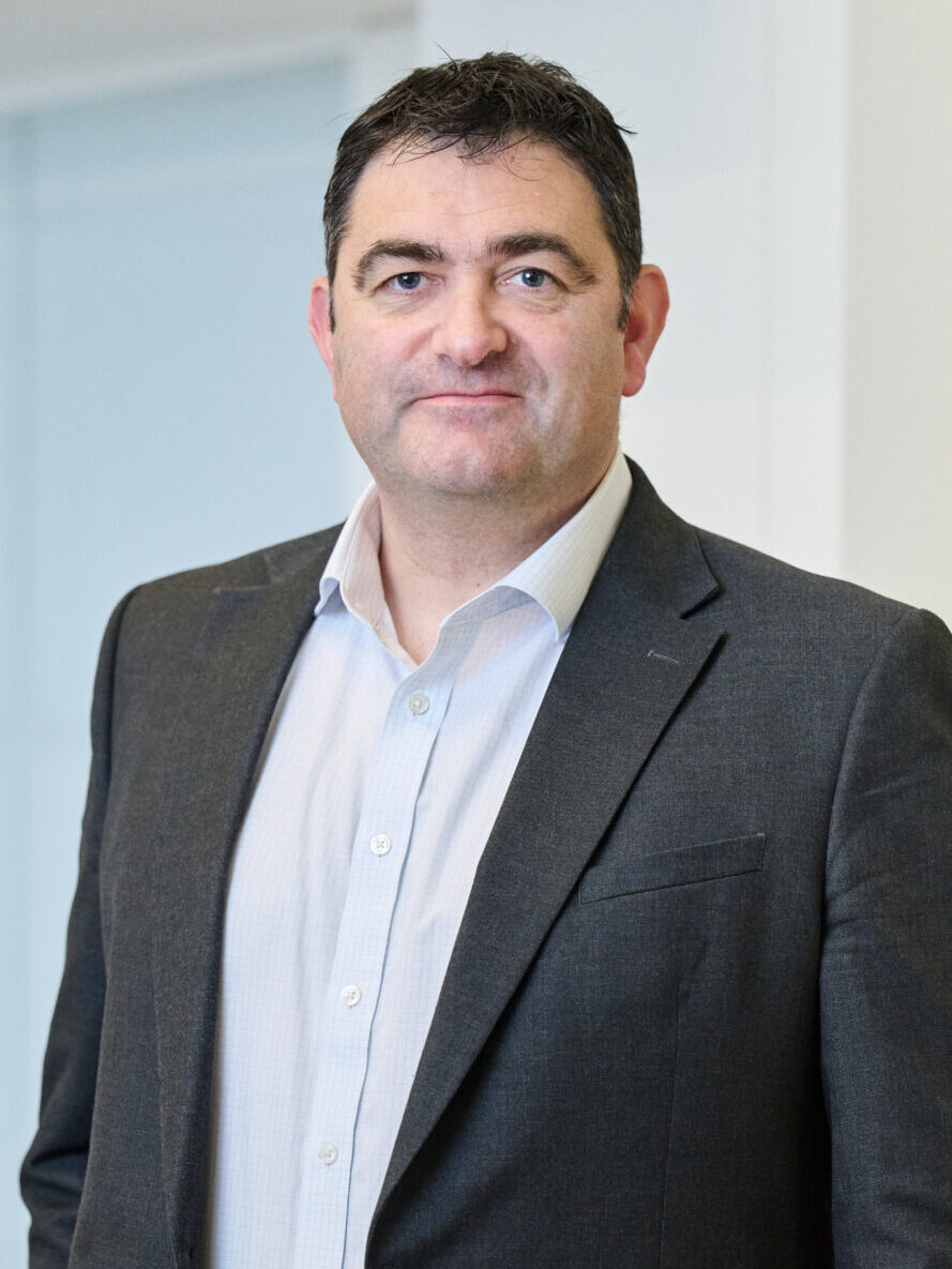
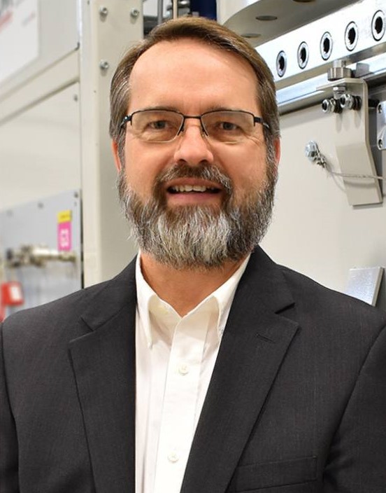
About the Guest
Vice President of Sales and Marketing
RoMan Manufacturing
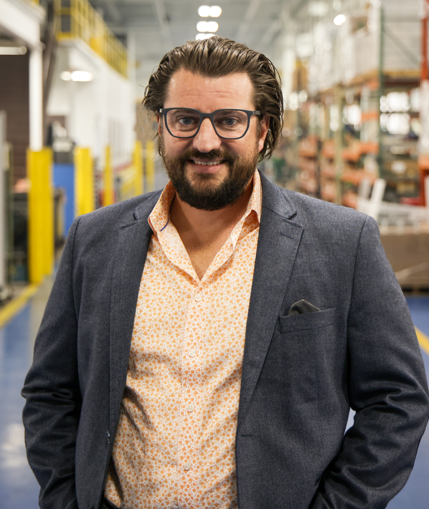
Casey O’Neill is vice president of Sales and Marketing at RoMan Manufacturing, a Grand Rapids, Michigan-based manufacturer of high-current, low-voltage power conversion equipment serving industries including resistance welding, glass, furnace, and other industrial applications.
Casey leads RoMan’s sales, marketing, and market-development efforts with a focus on strategic growth, client partnerships, and expanding RoMan’s presence in global industrial markets. His background includes leadership roles in sales strategy, business development, operations, and manufacturing, giving him a practical understanding of how technical solutions, commercial strategy, and client needs intersect.
For Heat Treat Today, Casey brings a perspective shaped by working closely with industrial clients in demanding thermal-processing, furnace, and power-conversion applications.
For more information: Contact Casey O’Neill at coneill@romanmfg.com.

Heat Treat Radio #134: Optimizing Power Delivery in Thermal Processing Read More »