Ask The Heat Treat Doctor®: Why and How Do We Heat Treat Gears? Part Two

Ask The Heat Treat Doctor® has returned to bring sage advice to Heat Treat Today readers and to answer your questions about heat treating, brazing, sintering, and other types of thermal treatments as well as questions on metallurgy, equipment, and process-related issues. In this installment, Dan Herring continues his discussion on gear heat treatment, exploring vacuum and induction hardening methods for gears — from low-pressure carburizing for advanced materials to single shot and tooth-by-tooth induction techniques — and how each can be matched to the specific demands of any gear application.
This informative piece was first released in Heat Treat Today’s March 2026 Annual Aerospace Heat Treating print edition.
In Part One of this discussion (Air & Atmospheres Heat Treating, February 2026), we discussed various gear types, materials, and how they can be atmosphere heat treated. This month, we are focusing on vacuum and induction heat treating methods. Let’s learn more.
Vacuum Heat Treatment Processing Methods
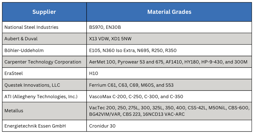
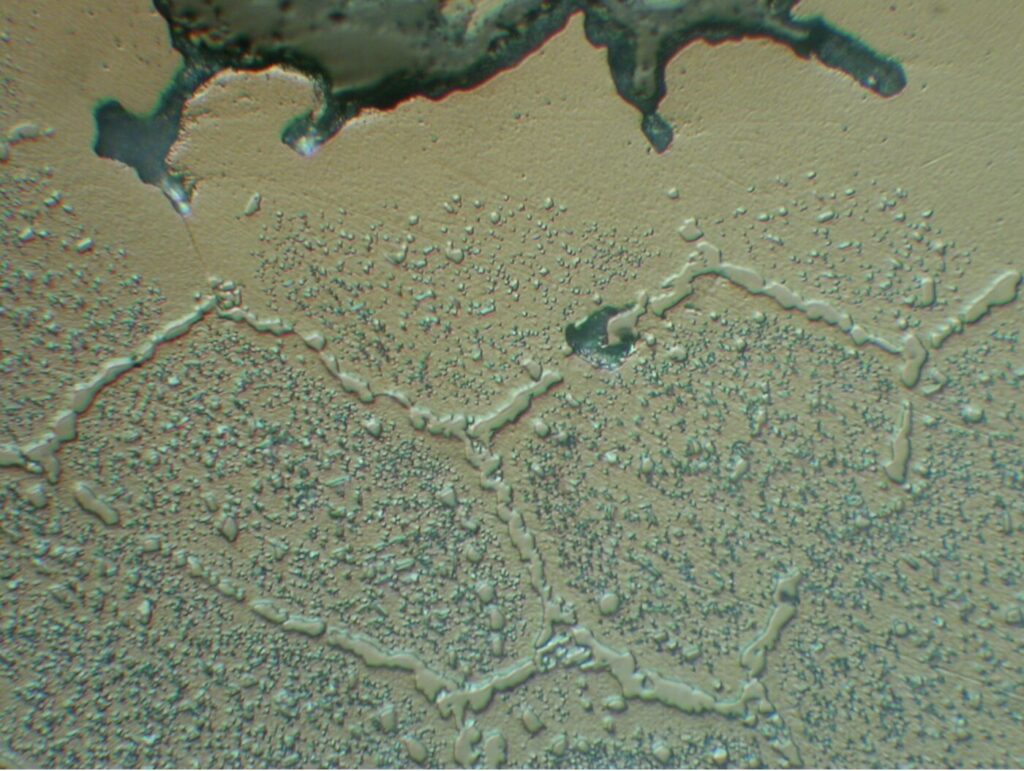
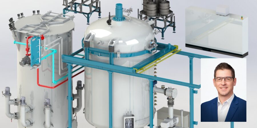
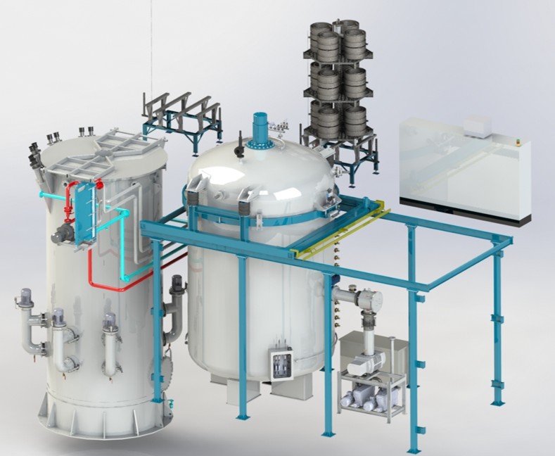
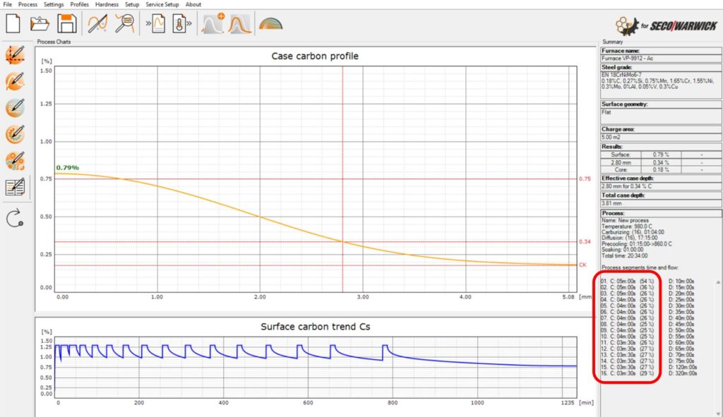
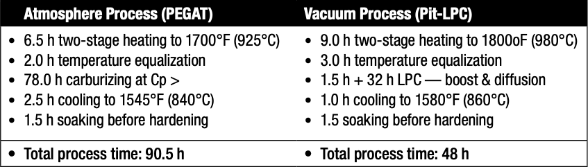
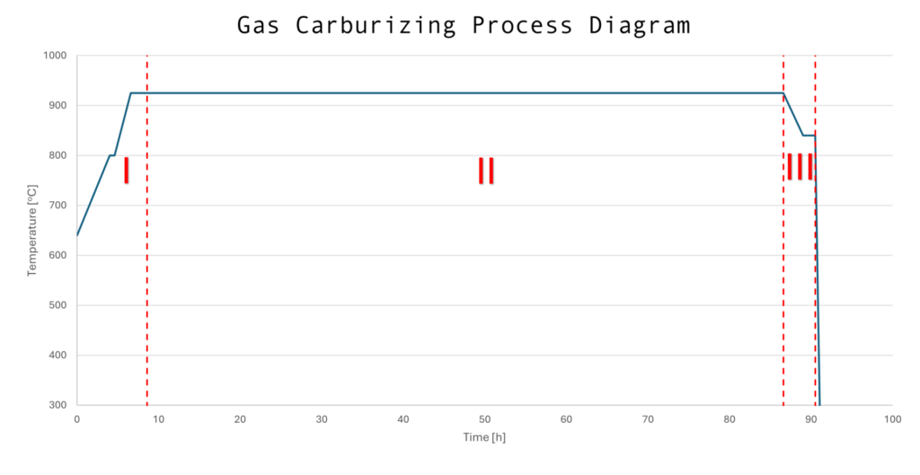
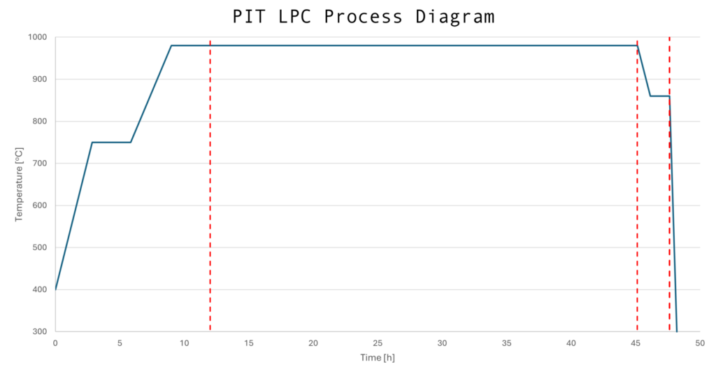
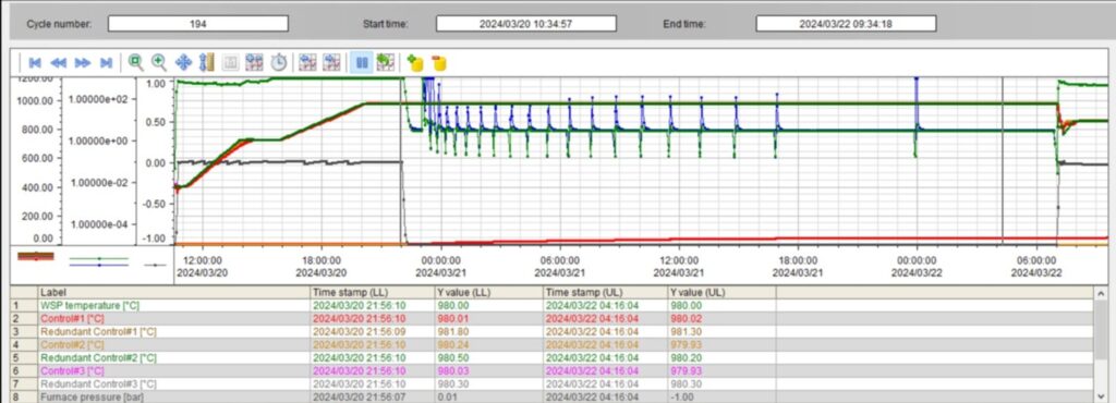
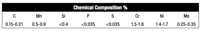
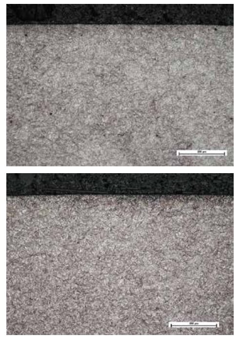
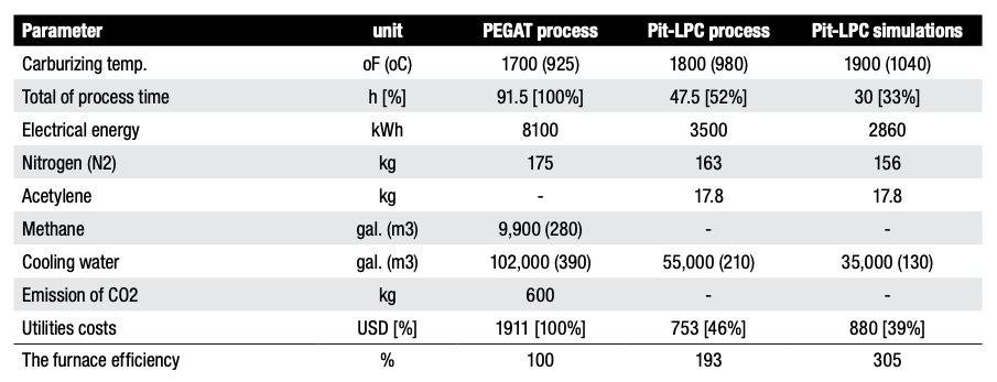
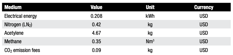
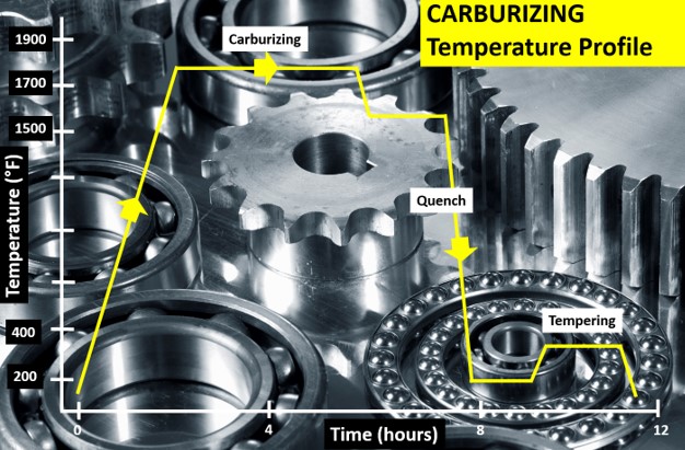
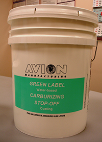
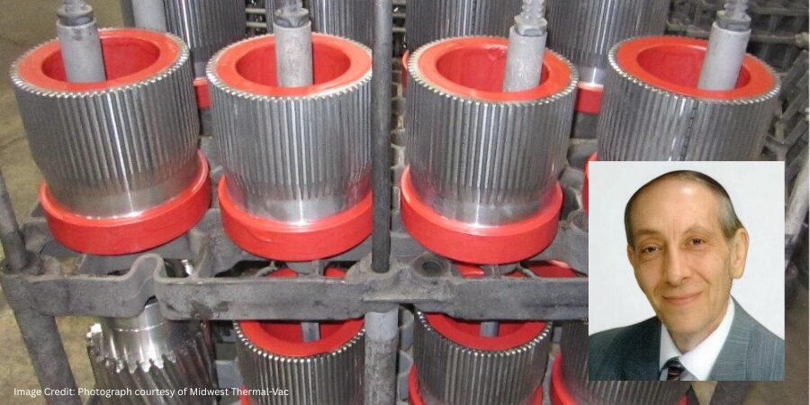
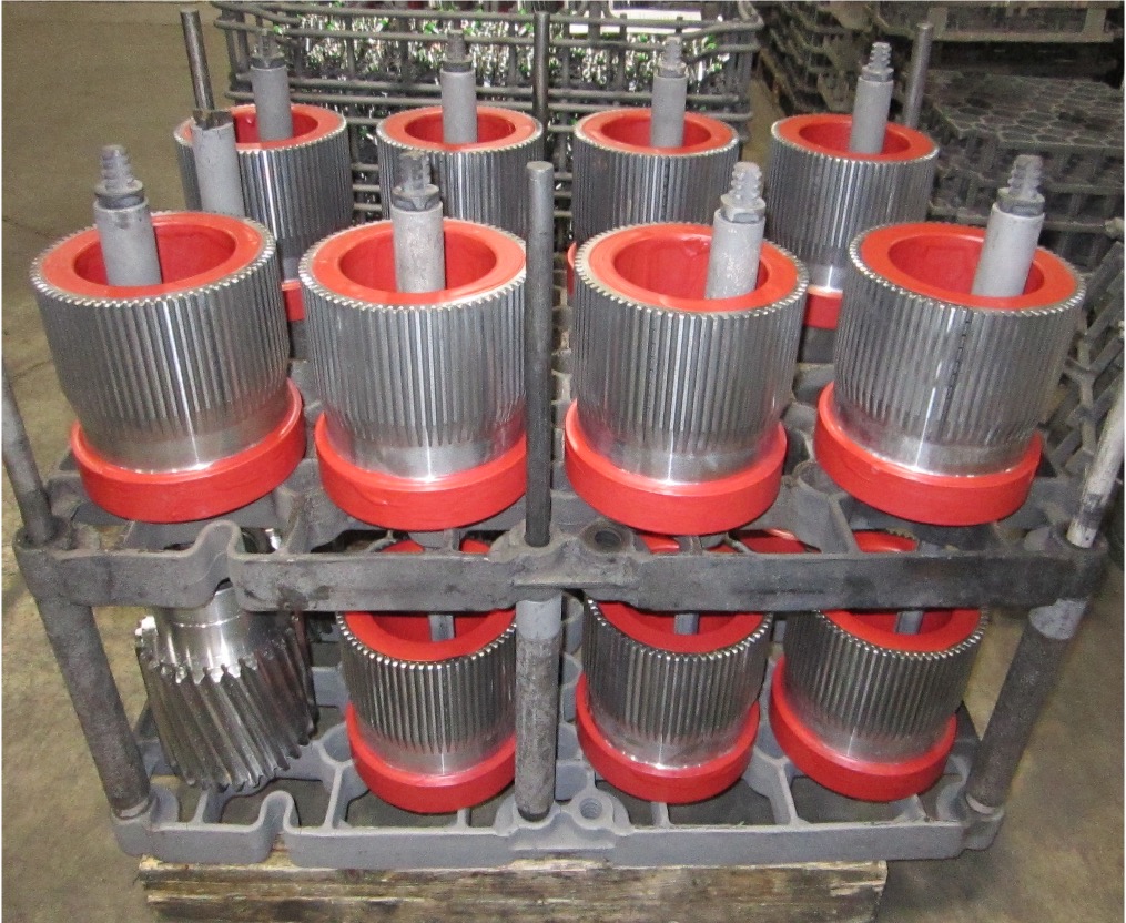
Vacuum processing can be used for most of the atmosphere treatments mentioned in Part One including carburizing (Figure 1). Low pressure carburizing (LPC) is a proven technology and the choice for many advanced applications in aerospace, automotive, off-highway, and motorsports markets, as well as the development of carburizing cycles for high-performance materials (Table A).

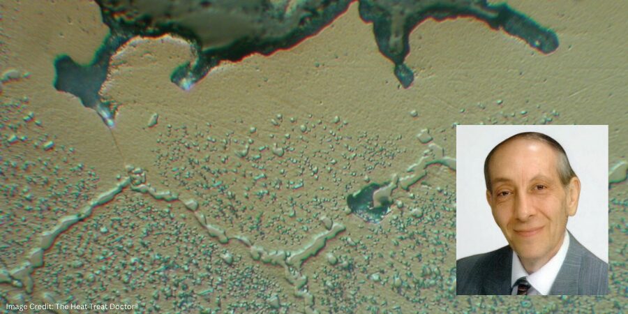
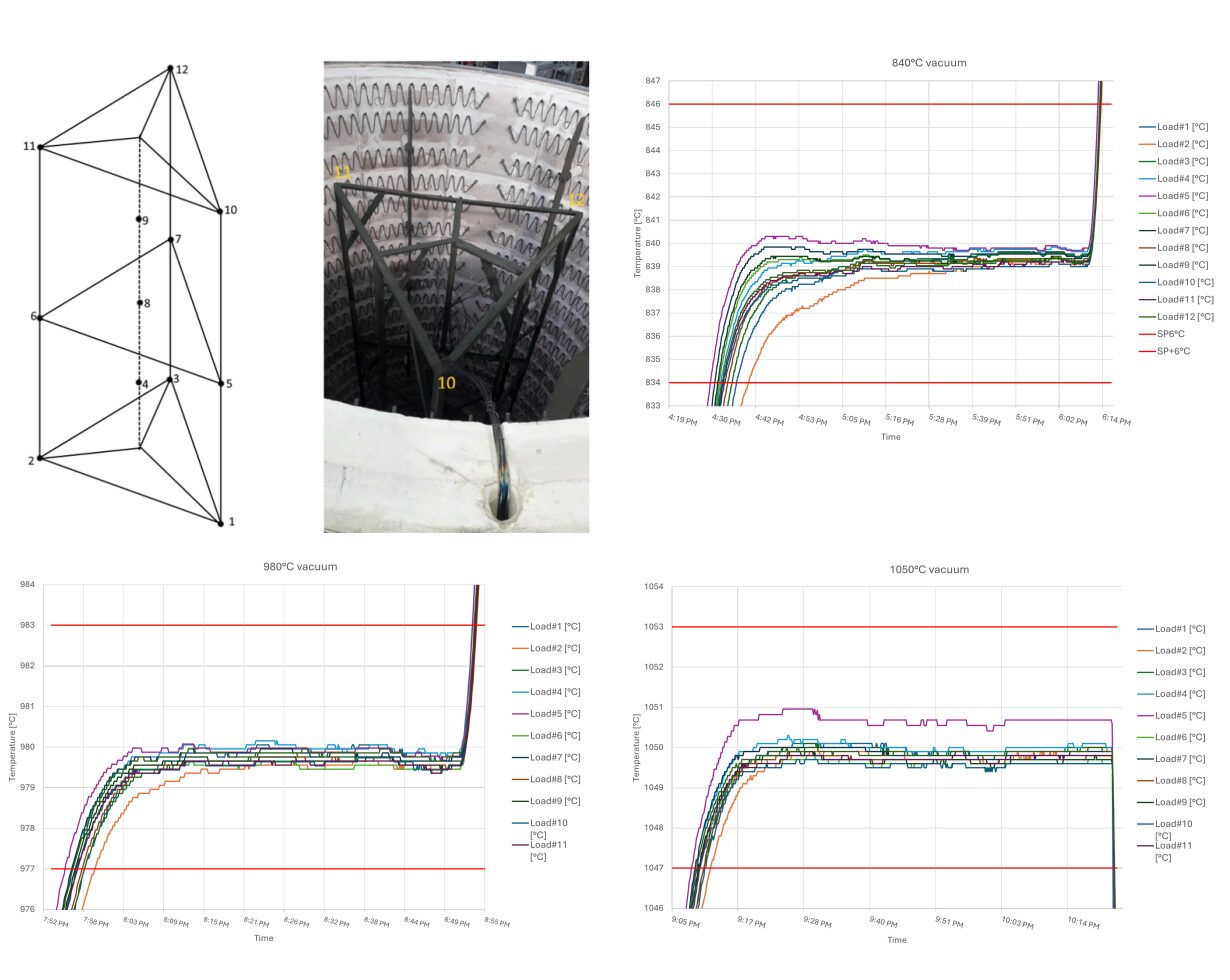
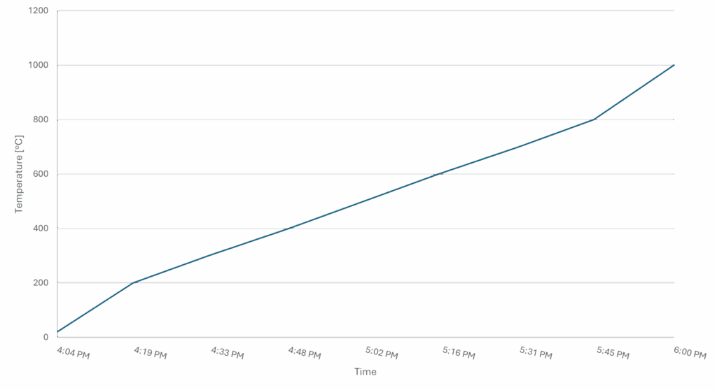
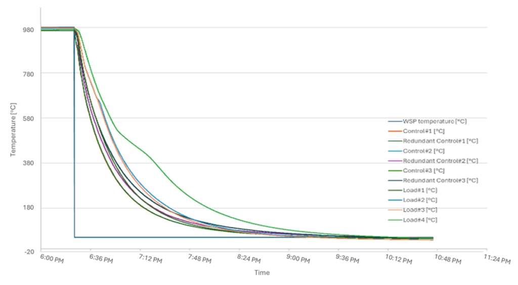
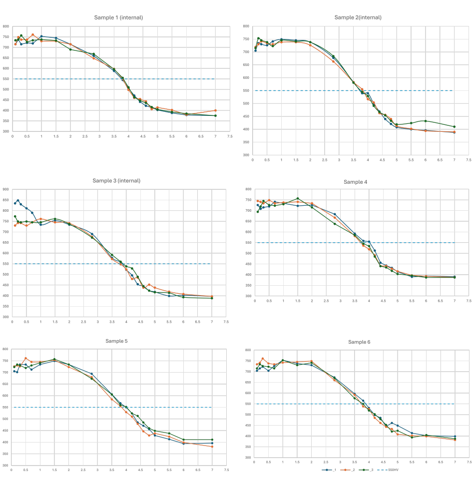
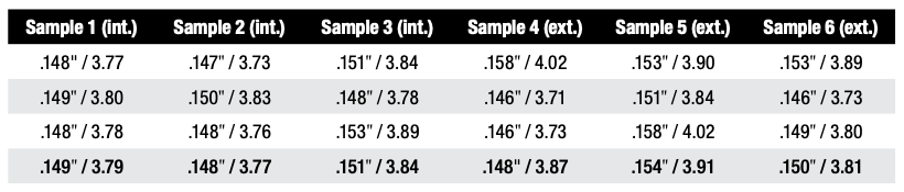
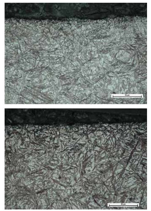
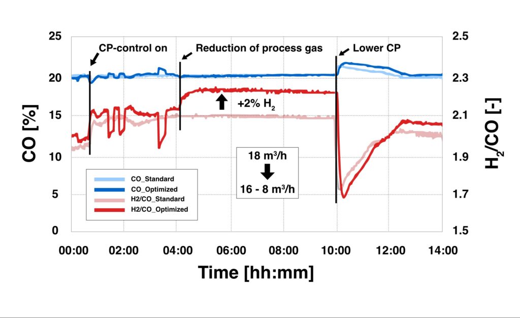
The range of effective case depths for most of these grades can range up to 2.0–3.0 mm (0.080–0.120 inches) without significant sacrifice of microstructure (Figure 2). Furnace variables, such as temperature uniformity (± 3°C or ± 5°F), control of cycle parameters (boost/diffuse times, gas flow rate, pressure, hydrocarbon type) and surface carbon optimize the microstructure, producing case uniformities of ± 0.05 mm (± 0.002 inches). Where permitted, the range of carburizing temperatures now includes the use of high temperature (> 980°C, or 1800°F) techniques.
All these advanced materials required extensive development testing to produce custom designed recipes to optimize cycle parameters. Also, quenching methods (Otto and Herring 2002) have improved, allowing us to achieve desired core properties with quenching parameter selection (high-pressure gas or oil) for distortion-sensitive and distortion-prone part geometries (Otto and Herring 2005, 2008).
Induction Hardening Methods
Various methods of hardening via applied energy are used in manufacturing gears, including flame hardening, laser surface hardening, and induction hardening.
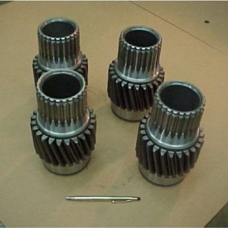
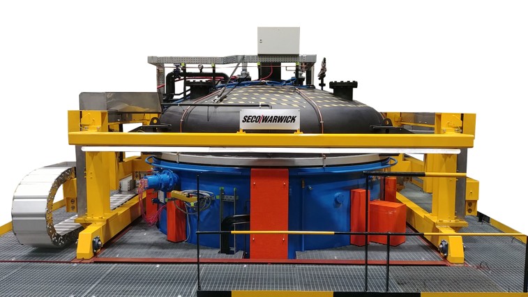
Of the various types of applied energy processing, induction hardening is the most common. Induction heating is a process that uses alternating electrical current that induces a magnetic field, causing the surface of the gear teeth to heat. The area is then quenched resulting in an increase in hardness within the heated area. This process is typically accomplished in a relatively short time. The final desired gear performance characteristics are determined not only by the hardness profile and stresses but also by the steel composition and prior microstructure. External spur and helical gears, bevel and worm gears, racks, and sprockets are commonly induction hardened. Typical gear steels include AISI/SAE grades 1050, 1060, 1144, 4140, 4150, 4350, 5150, and 8650.
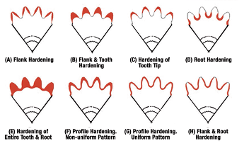
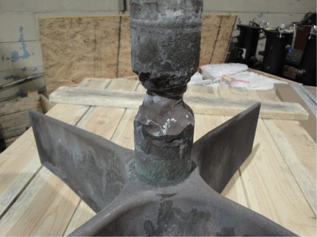
The hardness pattern produced by induction heating (Figure 3) is a function of the type and shape of inductor used, as well as the heating method. Quenching or rapidly cooling the workpiece can be accomplished by spray or submerged quench. The media typically used for the quench is a water-based polymer. The severity of this quenchant can be controlled by the polymer’s concentration. Cooling rates are usually somewhere in between what would be obtained from pure water and oil. In some unusual situations compressed air or nitrogen is used to quench the part.
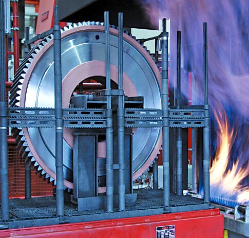
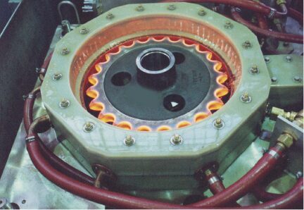
The most common methods for hardening gears and sprockets are by single shot (Figure 4) or the tooth-by-tooth method (Figure 5). Single shot often requires large kW power supplies but results in short heat/quench times and higher production rates. This technique uses a circumferential copper inductor, which will harden the teeth from the tips downward.
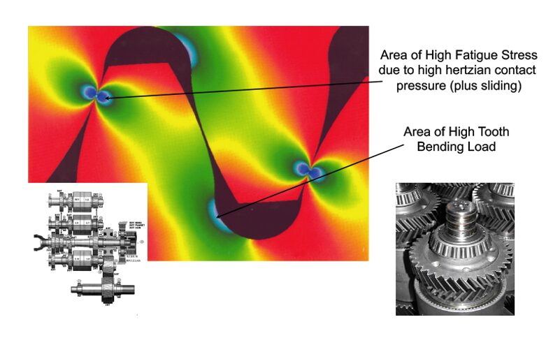
The larger and heavier loaded gears (where pitting, spalling, tooth fatigue, and endurance are issues) need a hardness pattern that is more profiled like those produced by carburizing, which can be obtained by tooth-by-tooth hardening. This method is limited to gear tooth sizes with modulus 4.23–5.08 (6 or 5 DP) using frequencies from 2 to 10 kHz and about 2.54 (10 DP) using a range of 25 to 50 kHz.
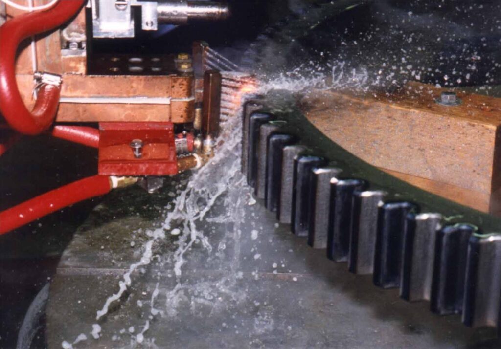
The lower the frequency, the deeper the case depth. Tooth-by-tooth hardening is a slow process and usually reserved for gears and sprockets that are too large to single shot due to power constraints. The process involves heating the root area and side flanks simultaneously, while cooling each side of the adjacent tooth to prevent temper-back on the backside of each tooth. The induction system moves the coil at a pre-programmed rate along the length of the gear. The coil progressively heats the entire length of the gear segment while a quench follower immediately cools the previously heated area. The distance from the coil to the tooth is known as coupling or air gap. Any changes in this distance can yield variation in case depth, hardness, and tooth distortion. The gear is indexed after each tooth has been hardened, often skipping a tooth. This requires at least two full revolutions in the process to complete the hardening of all teeth. Straight, spur, and helical gears up to 5.5 m (210 inches) weighing 6,800 kg (15,000 lb) have been processed with this method. The entire process yields a repeatable soft tip of the tooth with hard root and flank. In other applications, the tip and both flanks can be hardened simultaneously and yield a soft root.
In Summary
Today’s design engineer has the good fortune of being able to choose from a number of heat treatment technologies for any given type of gear material and design. When selecting a gear hardening method, it is essential to specify not only the desired mechanical and metallurgical properties, but the critical dimensions that must be held and even the desired stress state of the gears themselves. The secret to success is understanding the advantages and limitations of each technology and taking these into consideration when determining the overall cost of gear manufacturing.
References
Herring, Daniel H. 2004a. “Gear Heat Treatment: The Influence of Materials and Geometry.” Gear Technology, March/April.
Herring, Daniel H. 2004b. “Reducing Distortion in Heat-Treated Gears.” Gear Solutions, June.
Herring, Daniel H. 2007a. “Oil Quenching Technologies for Gears.” With Steven D. Balme. Gear Solutions, July.
Herring, Daniel H. 2007b. “Heat Treating Heavy Duty Gears.” With Gerald D. Lindell. Gear Solutions, October.
Herring, Daniel H. 2012–2016. Vacuum Heat Treatment. Vols. 1–2. BNP Media Group.
Herring, Daniel H. 2014–2015. Atmosphere Heat Treatment. Vols. 1–2. BNP Media Group.
Herring, Daniel H., Gerald D. Lindell, D. J. Breuer, and B. Matlock. 2001. “Atmosphere vs. Vacuum Carburizing.” Heat Treating Progress, November.
Herring, Daniel H., Gerald D. Lindell, D. J. Breuer, and B. Matlock. 2002. “An Evaluation of Atmosphere and Vacuum Carburizing Methods for the Heat Treatment of Gears.” In Off-Highway Conference Proceedings. SAE International.
Otto, Frederick J., and Daniel H. Herring. 2002a. “Gear Heat Treatment: Today and Tomorrow, Part 1.” Heat Treating Progress, June.
Otto, Frederick J., and Daniel H. Herring. 2002b. “Gear Heat Treatment: Today and Tomorrow, Part 2.” Heat Treating Progress, July/August.
Otto, Frederick J., and Daniel H. Herring. 2005. “Vacuum Carburizing of Aerospace and Automotive Materials.” Heat Treating Progress, January/February.
Otto, Frederick J., and Daniel H. Herring. 2007. “Advancements in Precision Carburizing of Aerospace and Motorsports Materials.” Heat Treating Progress, May/June.
Otto, Frederick J., and Daniel H. Herring. 2008. “Improvements in Dimensional Control of Heat Treated Gears.” Gear Solutions, June.
Rudnev, V. 2000. “Gear Heat Treating by Induction.” Gear Technology, March/April.
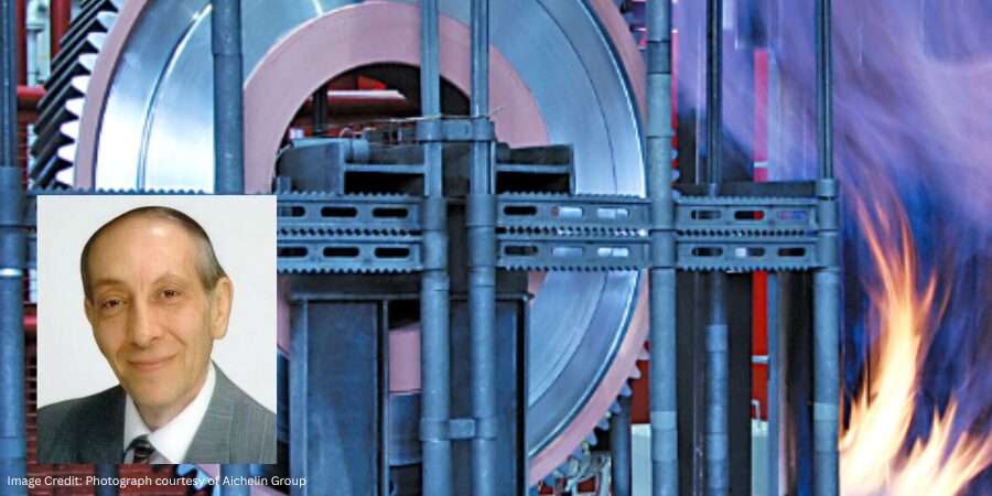
About the Author

“The Heat Treat Doctor”
The HERRING GROUP, Inc.
Dan Herring has been in the industry for over 50 years and has gained vast experience in fields that include materials science, engineering, metallurgy, new product research, and many other areas. He is the author of six books and over 700 technical articles.
For more information: Contact Dan at dherring@heat-treat-doctor.com.
For more information about Dan’s books: see his page at the Heat Treat Store.

Ask The Heat Treat Doctor®: Why and How Do We Heat Treat Gears? Part Two Read More »