Achieving the elimination of oxidation during thermal treatment has driven heat treaters for decades and resulted in a wide variety of approaches. The obvious method is to flow an inert gas such as nitrogen into the furnace in order to drive out both air and moisture. By itself, however, this technique is inadequate.
The zirconia carbon sensor has been used for nearly three decades to control the carbon potential in many carburizing applications. Today’s best of the web article examines the use of the zirconia carbon sensor in a variety of annealing and special treatment applications and considers how the sensor millivolt output is preferred because it relates directly (not empirically) to the free oxygen concentration in the surrounding environment.
An Excerpt:
“While it is desirable to avoid oxidation during thermal treatment, the achievement of adequate control using one of the ‘getter’ gases requires that the sensor millivolts achieved be established at some value higher than the vee formed by the iron reaction at temperatures below 1375ºF and the carbon reaction above that temperature. The vee will demonstrate the lower limit, but the practical level should be established by evaluation of product quality, getter cost and possible sooting. The appropriate level will be limited by such things as furnace leaks, atmosphere agitation, work porosity, time of treatment, etc.”
The future of heat treating requires new manufacturing solutions like robotics that can work with modular design. Yet so also does temperature monitoring need to be seamless to know how effectively your components are being heat treated — especially through being quenched.In this Technical Tuesday,learn more abouttemperature monitoring through the quench process.
Gas Carburization
Contact us with your Reader Feedback!
Carburizing has rapidly become one of the most critical heat treatment processes employed in the manufacture of automotive components. Also referred to as case hardening, it provides necessary surface resistance to wear, while maintaining toughness and core strength essential for hardworking automotive parts.
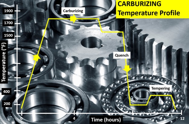
Figure 1. Typical carburizing heat treat temperature profile showing the critical temperature/time steps: (i) carburization, (ii) quench, and (iii) temper. (Source: PhoenixTM)
The carburizing process is achieved by heat treating the product in a carbon rich environment (Figure 1), typically at a temperature of 1562°F–1922°F (850°C–1050°C). The temperature and process time significantly influence the depth of carbon diffusion and other related surface characteristics. Critical to the process is a rapid quenching of the product following the diffusion in which the temperature is rapidly decreased to generate the microstructure, giving the enhanced surface hardness while maintaining a soft and tough product core.
The outer surface becomes hard via the transformation from austenite to martensite while the core remains soft and tough as a ferritic and/or pearlitic microstructure. Normally, carburized microstructures following quench are further tempered at temperatures of about 356°F (180°C) to transform some of the brittle martensite into tempered martensite to enhance ductility and grindability.
Critical Process Temperature Control
As discussed, the success of carburization is dependent on accurate, repeatable control of the product temperature and time at that temperature through the complete heat treatment process. Important to the whole operation is the quench, in which the rate of cooling (product temperature change) is critical to achieve the desired changes in microstructure, creating the surface hardness. It is interesting that the success of the whole heat treat process can rest on a process step which is so short (minutes), in terms of the complete heat teat process (hours). Getting the quench correct is not only essential to achieve the desired metal microstructure, but also to ensure that the physical dimensions and shape of the product are maintained (no distortion/warping) and issues such as quench cracking are eliminated.
Obviously, as the quench is so critical to the whole heat treat process, the correct quench selection needs to be made to achieve the optimum properties with acceptable levels of dimensional change. Many different quenchants can be applied with differing quenching performances. The rate of heat transfer (quench rate) of quench media in general follows this order from slowest to quickest: air, salt, polymer, oil, caustic, and water.
Technology Challenges for Temperature Monitoring
When considering carburization from an industry standpoint, furnace heat treat technology generally falls into one of two camps, embracing either air quench (low pressure carburization) or oil quench (sealed gas carburization/LPC with integral or vacuum oil quench). Although each achieves the same end goal, the heat treat mechanisms and technologies employed are very different, as are the temperature monitoring challenges.
To achieve the desired carburized product, it is necessary to control and hence monitor the product temperature through the three phases of the heat treat process. Conventionally, product temperature monitoring would be attempted using the traditional trailing thermocouple method. For many modern heat treat processes including carburization, the trailing thermocouple method is difficult and often practically impossible.1 The movement of the product or product basket from stage to stage, often from one independent sealed chamber to another (lateral or vertical movement), makes the monitoring of the complete process a significant challenge.
With the industry driving toward fully automated manufacturing, furnace manufacturers are now offering the complete package with full robotic product loading that includes shuttle transfer systems and modular heat treat phases to process both complete product baskets and single piece operations. Although trailing thermocouples may allow individual stages in the process to be measured, they cannot provide monitoring of the complete heat treat journey. Testing is therefore not under true normal production conditions, and therefore is not an accurate record of what happens in normal day to day operation.
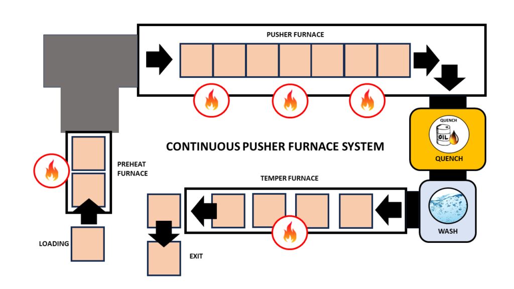
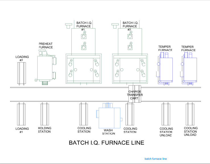
Figure 2 shows schematic diagrams of two typical carburizing furnace configurations that would not be possible to monitor using trailing thermocouples. The first shows a modular batch furnace system where the product basket is transferred between each static heat treat operation (preheat, carburizing furnace, cooling station, quench, quench wash, temper furnace) via a charge transfer cart. The second shows the same heat treat operation but performed in a continuous indexed pusher furnace configuration where the product basket moves sequentially through each heat treat operation in a semi-continuous flow.
Thru-process temperature monitoring as a technique overcomes such technical restrictions. The data logger is protected by a specially designed thermal barrier, therefore, can travel with the product through each stage of the process measuring the product/process temperature with short, localized thermocouples that will not hinder travel. The careful design and construction of the monitoring system is important to address the specific challenges that different heat treat technology brings including modular batch and continuous pusher furnace designs (Figure 2).2
The following section will focus specifically on monitoring challenges of the sealed gas carburizing process with integral oil quench. Technical challenges of the alternative low pressure carburizing technology with high pressure gas quench have previously been discussed in an earlier publication.3
Monitoring Challenges of Sealed Gas Carburization — Oil Quench
Figure 3. “Thru-process” temperature monitoring system for use in a sealed carburizing furnace with integral oil quench — (3.1) Monitoring system entering furnace with thermocouple fixed to automotive gears, product test pieces (3.2) System exiting oil quench tank (3.3) System inserted into wash tank with product basket (Source: PhoenixTM)
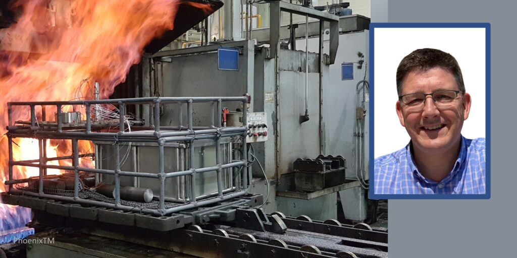
Presently, the most common traditional method of gas carburizing for automotive steels is often referred to as sealed gas carburizing. In this method, the parts are surrounded by an endothermic gas atmosphere. Carbon is generated by the Boudouard reaction during the carburization process, typically at 1562°F–1832°F (850°C –1000°C). Despite the dramatic appearance of a sealed gas carburizing furnace, with its characteristic belching flames (Figure 3), from a monitoring perspective, the most challenging aspect of the process is not the heating, but the oil quench cooling. For such furnace technology, the historic limitation of “thru-process” temperature profiling has been the need to bypass the oil quench and wash stations, missing a critical process step from the monitoring operation. Obviously, passing a conventional hot barrier through an oil quench creates potential risk of both system damage from oil ingress and barrier distortion, as well as general process safety. However, the need to bypass the quench in certain furnace configurations by removing the hot system from the confined furnace space could create significant operational challenges, from an access and safety perspective.
Monitoring of the quench is important as ageing of the oil results in decomposition (thermal cracking), oxidation, and contamination (e.g. water) of the oil, all of which degrade the viscosity, heat transfer characteristics, and quench efficiency. Control of physical oil temperature and agitation rates is also key to oil quench performance. Quench monitoring allows economic oil replacement schedules to be set, without risk to process performance and product quality.
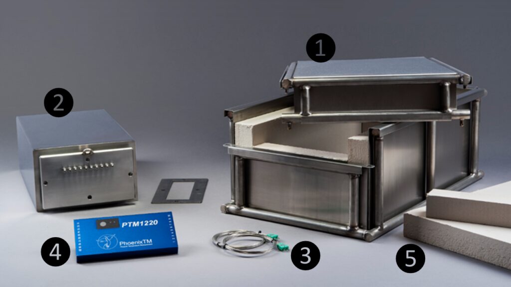
Figure 4. “Thru-process” temperature monitoring system oil quench compatible thermal barrier design: (1) Robust outer structural frame keeping insulation and inner barrier secure; (2) Internal thermal barrier — completely sealed with integral microporous insulation protecting data logger; (3) Mineral insulated thermocouples sealed in internal thermal barrier with oil tight compression fitting; (4) Multi-channel high temperature data logger; and (5) Sacrificial insulation blocks replaced after each run.
(Source: PhoenixTM)
To address the process challenges, a unique thermal barrier design has been developed that both protects the data logger in the furnace (typically three hours at 1697°F/925°C) and also protects during transfer through the oil quench (typically 15 mins) and final wash station (Figure 3). The key to the barrier design is the encasement of a sealed inner barrier with its own thermal protection with blocks of high-grade sacrificial insulation contained in a robust outer structural frame (Figure 4).
Quench Cooling Phases
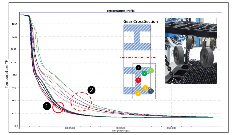
Monitoring the oil quench in carburization gives the operator a unique insight into the product’s specific cooling characteristics, which can be critical to allow optimal product loading and process understanding and optimization. From a scientific perspective, the quench temperature profile trace, although only a couple of minutes in duration, is complex and unique. From a zoomed in quench trace (Figure 5) taken from a complete carburizing profile run, the three unique heat transfer phases making up the oil quench cool curve can be clearly identified:
Figure 5. Oil quench temperature profile for different locations on an automotive gear test piece shows the three distinct heat transfer phases: (1) film boiling “vapor blanket”, (2) nucleate boiling, and (3) convective heat transfer. (Source: PhoenixTM)
Film boiling “vapor Blanket”: The oil quenchant creates a layer of vapor (Leidenfrost phenomenon) covering the metal surface. Cooling in this stage is a function of conduction through the vapor envelope. Slow cool rate since the vapor blanket acts as an insulator.
Nucleate boiling: As the part cools, the vapor blanket collapses and nucleate boiling results. Heat transfer is fastest during this phase, typically two orders of magnitude higher than in film boiling.
Convective heat transfer: When the part temperature drops below the oil boiling point. the cooling rate slows significantly. The cooling rate is exponentially dependent on the oil’s viscosity.
From a heat treat perspective, the quench step relative to the whole process (hours) is quick (seconds), but it is probably the most critical to the performance of the metallurgical phase transitions and achieving the desired core microstructure of the product without risk of distortion. By being able to monitor the quench step, the process can be validated for different products with differing size, form, and thermal mass. As shown in Figure 6, the quench curve profile over the three heat transfer phases is very different for two different automotive gear sizes.
Figure 6. Oil quench temperature profile for different automotive gear sizes (20MnCr5 case hardening steel) with different thermal masses: Passenger Car Gear (2.2 lbs) and Commercial Vehicle Gear (17.6 lbs) (Source: PhoenixTM)
Summary
As discussed in this article, one of the key process performance factors associated with gas carburization is the control and monitoring of the product quench step. Employing an oil quench, the measurement of such operation is now very feasible as part of heat treat monitoring. Innovations in thru-process temperature profiling technology offer specific system designs to meet the respective application challenges.
References
[1] Dr. Steve Offley, “The light at the end of the tunnel – Monitoring Mesh Belt Furnaces,” Heat Treat Today, February 2022, https://www.heattreattoday.com/processes/brazing/brazing-technical-content/the-light-at-the-end-of-the-tunnel-monitoring-mesh-belt-furnaces/.
[2] Michael Mouilleseaux, “Heat Treat Radio #102: Lunch & Learn, Batch IQ Vs. Continuous Pusher, Part 1,” interviewed by Doug Glenn, Heat Treat Radio, October 26, 2023, audio, https://www.heattreattoday.com/media-category/heat-treat-radio/heat-treat-radio-102-102-lunch-learn-batch-iq-vs-continuous-pusher-part-1/.
[3] Dr. Steve Offley, “Discover the DNA of Automotive Heat Treat: Thru-process Temperature Monitoring,” Heat Treat Today, August 2023, https://www.heattreattoday.com/discover-the-dna-of-automotive-heat-treat-thru-process-temperature-monitoring/.
About the Author
Dr Steve Offley (“Dr O”), Product Marketing Manager, PhoenixTM
Dr. Steve Offley, “Dr. O,” has been the product marketing manager at PhoenixTM for the last five years after a career of over 25 years in temperature monitoring focusing on the heat treatment, paint, and general manufacturing industries. A key aspect of his role is the product management of the innovative PhoenixTM range of thru-process temperature and optical profiling and TUS monitoring system solutions.
Our readers and Heat Treat Radiolisteners will remember a recent episode entitled "Heat Treat Radio #102: Lunch & Learn, Batch IQ Vs. Continuous Pusher, Part 1." Today's Technical Tuesday article is a continuation of this dialog, with Michael Mouilleseaux, a boot-on-the-ground North American heat treat expert from Erie Steel here to answer your questions on the maintenance of batch and continuous pusher furnace systems.
Doug Glenn, Heat TreatToday's publisher,Karen Gantzer, associate publisher/editor-in-chief, join in this Technical Tuesday article.
Stay tuned for a Part 2 continuation of the Lunch and LearnHeat Treat Radio episode, coming to Heat Treat Radio in a couple weeks.
Below, you can watch the video or read from an edited transcript.
Michael Mouilleseaux
General Manager at Erie Steel, Ltd.
Sourced from the author
Introduction to Maintenance
Doug Glenn: We would like to move on to maintenance of the batch furnace and the continuous furnace. What is the cost of maintaining and operating these furnaces?
Michael Mouilleseaux: When they are utilized in a carburizing environment, there is always excess carbon that falls out or precipitates out of the atmosphere, and it ends up as elemental carbon in the bottom of the furnace.
What do you do with that? In furnaces that are using a carburizing environment, the burnout of the furnace is easily the single most important piece of preventative maintenance that you can perform. How is that performed? First, the furnace is vacated; there is no product in the furnace, the temperature is reduced — typically, you want it down around 1500°F or 1550°F — and you introduce room air into the furnace. The room air ignites the carbon. It’s a very primitive operation.
So, what temperature does carbon burn at? It burns at 3000°F.
You need to be very careful. It’s a controlled burn because you can actually damage the furnace through refractory, through the alloy that’s in the furnace, or it can get away. How do you do control it? On one level, you’re just looking at the temperature control. If you have it set at 1550, you’re going to say, “I’m only going to put air as long as the temperature of the furnace does not go up more than 25°F or 50°F.” It’s somewhat dependent upon the piece of equipment and is one of those things that you learn empirically; there is not a hard and fast rule for it.
Then, you can shut off the air. If there is no oxygen, then the source for combustion is taken away and you stop that operation. If you need to do it more rapidly than that, you may need to flood the furnace with nitrogen. Typically, if you have to flood the furnace with nitrogen to do it, you’ve been a little too aggressive in your burnout.
How long do you perform that? The great thing with oxygen probes is that you can utilize your oxygen probe to help you learn when you have burnt out the furnace. You’re not getting an actual carbon atmosphere, but what you do get is a readout from the probe. What you can do is perform the burnout operation until you attain that level and then you know that you’ve done a sufficient job in burning it out. That’s the single most important piece of preventative maintenance that’s done on a furnace used for carburizing.
Doug Glenn: Is that both in batch and in continuous?
Michael Mouilleseaux: Identical, yes.
Doug Glenn: I’ve got a couple other questions about furnace burnouts as someone who’s not a furnace operator. You said that there’s “carbon dropout” in the furnace. I know that in some furnaces, parts of the atmosphere may precipitate onto the coolest part of the furnace. Is that what is happening, or are we talking about carbon powder at the bottom of a furnace?
Michael Mouilleseaux: It is carbon powder, and it becomes more egregious. The powder then begins to accumulate into pebbles, nuggets, and larger size pieces. That’s more problematic. When it is in a powdered form, that is the best.
The question will be: How often do you have to do this? As with everything, the answer is — it depends. It depends on what you’re doing; it depends on how aggressive you are in your carburizing.
In the boost phase, we talked about carburizing at upwards of 1%. As soon as you exceed the saturation level of carbon, you’re going to precipitate out the excess carbon. What is that number? It’s different for every temperature. At 1500°F, it’s .9 or .85; at 1750°F, it’s 1.25. But to attain that, you’re actually putting natural gas into the furnace, and the amount of natural gas that you put into the furnace and its dissociation rate — the rate that it breaks down — can then subsequently be diffused into the parts; all of that comes into play.
With saturation levels of carburizing, there is always some residual carbon that’s in the furnace.
Doug Glenn: You mentioned that carbon burns at around 3,000 degrees. Are you taking the furnace up to that temperature?
The great thing with oxygen probes is that you can utilize your oxygen probe to help you learn when you have burnt out the furnace. You’re not getting an actual carbon atmosphere, but what you do get is a readout from the probe. What you can do is perform the burnout operation until you attain that level and then you know that you’ve done a sufficient job in burning it out. That’s the single most important piece of preventative maintenance that’s done on a furnace used for carburizing
Michael Mouilleseaux: No. The burnout cycle is at 1500 or 1550. You raise that carbon to that level and introduce oxygen, and what you want is a slow burn.
We next think about the systems involved in the furnace. First there is the heating system. In a gas-fired furnace, some critical things to consider are burner recovery, burner adjustment, and the amount of excess air that results in that burner adjustment. That’s a preventative maintenance operation that needs to be performed on a regular basis. It probably doesn’t need to be done daily, but monthly is optimal. If everything is very steady, including the barometric pressure, then you don’t need to do all of those adjustments.
Now, electric furnaces have SCRs that fire the elements, and you have to pay attention to the tuning of those things to make sure that they’re operating at optimum performance. One of the ways that you can do that, in a batch furnace, is if you look at the recovery time.
For example, if you have a load that weighs 4000 lbs. and you put it in the furnace and you know that it takes an hour and a half for the furnace to recover to temperature, but then all of a sudden, it takes an hour and 45 minutes, or an hour and 50 minutes, or two hours, obviously the burners are not producing the same amount of heat. The burners are not pumping the requisite amount of BTUs to achieve that recovery time. Could that be related furnace circulation? Could it be related to the insulation in the furnace? At an extreme, it could. Typically, though, it’s related to burner or SCR tuning.
Those are the kinds of things that are very easy to pay attention to.
"Electric furnaces have SCRs that fire the elements, and you have to pay attention to the tuning of those things to make sure that they’re operating at optimum performance. One of the ways that you can do that, in a batch furnace, is if you look at the recovery time."
Setting up PM Through Controls System
The control schemes in the PLC are typically very robust. So, you can establish a program and the PLC is going to say, “I want to heat it at this rate, I want the carbon potential to be .4%, I want to hold this at two hours at temperature, and then I want to initiate a quenching cycle.” Typically, PLCs are quite robust.
The thing you have to be careful with is obviously not just power outages, but brownouts. Brownouts are when you don’t quite lose all voltage, but you lose some of it. If you don’t have some kind of a filter on the power you can mitigate with, or have an uninterruptable power supply for the PLC, you can damage those things, resulting in some major work on the PLC.
The other part of that is the furnace circulation. We’ve got fans in these furnaces, and we circulate the atmosphere. The primary stages of heating in the furnace are convection, until we get to 1200 degrees. How do we convect the heat? We have the atmosphere in the furnace, the fan circulates, it washes the atmosphere down the radiant tubes, it heats up the atmosphere, the atmosphere comes into contact with the components, and we’re convection-heating the parts.
Once we get to 1200 degrees or more, then the primary method of heating becomes radiant heating. That’s where the radiant tubes are then the primary means of transferring energy. But the fans become very important. Are they balanced? Is the RPM correct? Is the amp reading on the fan? Those are areas to look at.
You have to understand how the furnace operates when it’s healthy — the furnace manufacturer can help you and/or you just learn empirically. For instance, what would it mean if, all of a sudden, I’m drawing much fewer amps on a circulating fan and it’s running very rough? Quite possibly, we’ve lost a fan blade.
Then there is the atmosphere control system. All that we just described is applicable to both continuous and batch furnaces. The furnace needs to be sealed and you want a couple inches of water column pressure — excess pressure — in the furnace relative to atmosphere pressure, since safety is the number one concern.
The atmosphere that we’re talking about in most of these furnaces is endothermic atmosphere. It’s a reducing atmosphere, meaning that it’s combustible. If, of course, we have combustion in a closed vessel, that’s called an explosion.
The reducing atmosphere, in and of itself, is if you look in a furnace that is at anything above 1200 degrees where it’s red, up to 1700–1800 degrees where it’s going to be yellow to white — and there is no flame . . . . People are absolutely amazed when they look in an atmosphere furnace and they see no flame. What you should see is everything in a relative, uniform color. The parts should be a uniform color. If you look at the tubes, they should be a little lighter because the tubes will always be somewhat above the temperature of the parts . . . .
Back to the atmosphere: We want to be sure that the atmosphere stays in the furnace and that we maintain that pressure in the furnace. So, what would be a cause to lower the pressure in the furnace? A door leak or a leak in a fan. It could be, if you have a mechanical handling system, a leak through that system. Those are all places to look.
The PM on that? For maintaining the level of lubrication in the fan bearings, see that they’re cooled so that the outlet temperature of the coolant — be it air or water — should be higher than the inlet temperature; that shows that they’re being cooled.
I can’t tell you an absolute number, but I can say that for the equipment that we have, we have numbers that we’ve developed; we know that if the outlet temperature of the water is 20 degrees higher than it is going in, we’re doing a good job of cooling the bearings.
The door seals in furnaces, typically, are brick on brick. Typically, they use a wedge system to seal the doors in the furnace. But, of necessity, these are wear items. Therefore, in preventative maintenance, you might notice a burnout around a door where you hadn’t had one before. That tells you that atmosphere is leaking out of that door and so a repair is needed in the near future.
An interesting thing about a batch furnace: Most of them only have one door. So, it’s quite easy — you can open the vestibule and, in a maintenance operation, if you gassed up the furnace, you could see.There is always going to be some atmosphere coming around the door because that’s where the atmosphere goes into the vestibule, but it should be at the top; it shouldn’t be around the sides, and it definitely shouldn’t be at the bottom. It should be very consistent.
That’s one of those things that, again, you empirically learn. You look at it — it’s a visual operation to say what you’re doing.
There are two other systems: First, the quench system. We talked about how critical the quench system is. The RPMs of the prop, the amp draw of the motors for the props — those things should be very consistent. I think they should be monitor and data logged. The reason for that is you want to know when you quench a load that the RPMs of those props are what you have set it for. When you introduce a load into the quench, the amp draw is, of necessity, going to increase. That’s because you’ve put something in the path of the quenchant so, in order to maintain that flow, you’ve increased the amount of work that it takes to rotate those props.
That’s the kind of thing that you want to monitor. If the amp draw is changing, that means that there’s something in the quench system. Could it be the bearings? Could it be the motor? Those are some things that you’d need to take a look at and be certain of. Obviously, the props need to be in balance; you don’t want any vibration in them.
Doug Glenn: This is also true on the continuous furnace. You’ve got three or four green props in the batch furnace, and it would be the same in the continuous furnace.
Source: Erie Steel, Ltd
Maintenance of Quenchant
Michael Mouilleseaux: Also, there is the maintenance of the quenchant. I’m of the belief that the quench should be continuously filtered. I’m not a fan of batch filtering. I’ve been doing this long enough that I’ve done that, and it just isn’t successful. Quite possibly there are operations that allow it.
If you’re carburizing, you’re going to have particulate in the quenchant because that same atmosphere precipitation of carbon finds its way into the quench. It’s going to be on the parts, it’s going to be on the trays, it’s going to be dragged in there. So, you have this particulate carbon in the quench and it acts as a catalyst to break down the oil.
One way to extend the life of the oil is to make sure that you’re continuously filtering that out. People say 50 microns or 100 microns or 25 microns. Experientially, I’m going to say that it’s going to be 25 microns. If you have a 100-micron filter, that’s great for getting the pebbles out of the quench or the scale, if that were to be an issue with your customer’s parts, but that’s not sufficient to filter out the particulate that’s going to be of the size that’s going to catalyze the breakdown of your quenchant.
Doug Glenn: I assume that if you’re providing for some sort of continuous filtering of your quench, that’s built into the quench structure. The quench tank is built for that, right, and you’re continually flowing it through this filter?
Michael Mouilleseaux: I’m not going to say that no manufacturers offer sufficient quench filtering, but I am not aware of anyone that offers a quench filtration system that’s sufficient. Most of these things end up being standalone. You want to draw the quenchant from the bottom of the tank in one quarter, you want to put it through a series of filters, and you want to put it back into the furnace at the opposite end of the quench tank.
I can say with certainty, that a batch furnace which has not been filtered well, if you remove the quenchant from the furnace after six months — definitely after 12 months — of using it in daily carburizing, you’re going to take 55-gallon drums of sludge out of the furnace, and the sludge is essentially carbon that’s mixed in with the oil.
For that same furnace, with a sufficient quench filtration system, there will be little pockets in the four corners of the quench tank, but that’s about it.
CQI-9, Nadcap and all of those standards have a requirement for monitoring of quenchant. One of the monitors should be particulate because that lets you know how good a job you’re doing in filtering.
Having done it properly, one can say, “Well, I have to replace my quench oil,” — fill in the blank — “once a year, once every six months, once every two years.” Properly maintained and filtered, the quenchant does not have to be replaced very often.
You’re going to drag out a little oil on every load. You want to let the load drip so that you’re not taking that precious quench oil and just putting it in the wash and washing it off. But in a batch furnace, you could have a couple hundred gallons a month to four hundred gallons, depending on the size of the furnace, of add-back that you’re putting in there. Is that sufficient to maintain all of the additives that are in the quenchant? Is that something that you need to monitor? Typically, the manufacturer can do that for you. You get monitoring and you see what the quench speed is, what is the viscosity, flash – all of those important pieces of information.
Now, it doesn’t come for free. A filtration system is costly, and the filters are costly. A year’s worth of quenchant is five years’ worth of filters. In my mind, that’s a good tradeoff.
Karen Gantzer: So, Michael, when the process is filtering the quench, does this happen during production downtime?
Karen Gantzer
Associate Publisher/ Editor in Chief
Heat Treat Today
Michael Mouilleseaux: No, it’s done continuously. Even when the furnace is not running on the weekend, you’re still filtering the oil. You’re going to be taking 20-50 gallons out of the quench tank but you’re putting it right back in. It just passes through filters.
Some people have utilized centrifuges. It’s a very successful way of filtering out carbon particles in oil. The caveat on that is you don’t want the oil above 140 degrees. If you get the oil above 140 degrees and for every 20 degrees you go up, you start doubling the oxidation rate of the oil.
In high-temperature oil, we do a fair amount of modified marquenching. We do it in closed canisters. The seals must be temperature-tolerant, but it is very successful.
The last part is going to be the quench heating and cooling. Typically, at the first part of the week when you’re starting up the furnace or if you’re going from operation A to operation B and it requires a higher temperature quenchant, you’re going to use either gas or electric elements that are going to heat it. Those things need to be monitored so that they’re available when you need them. The last thing that you want to do is start out the week and find out that the quench heaters don’t work; then, you’re trying to find a couple of dummy loads that you can heat up to put into the quench to heat up the quenchant before proceeding with operations.
Then, of great, importance is quench cooling. In petroleum-based quenchants, you’ve got a flashpoint of 400 degrees plus or minus — could be 350, could be 450, depending upon the quenchant that you’re using. You don’t want the temperature of that oil to approach that flashpoint. You do that by using a quench-cooling system. It’s a big radiator. You’ve got a pump, and you set it when you want the pump to go on. You pump the oil out to the quench coolant, and when it comes back, once you’ve attained what your temperature is, then you stop.
Doug Glenn: I’ve got a couple quick questions on this. First, is the quench heater an immersion tube?
Michael Mouilleseaux: Yes. Gas-fired tubes and gas-fired units are very small u-tubes that go into the quench tank. Electrical units have got elements that are tolerant to that.
Doug Glenn: Typically, you’re using those because you’re actually using the quenchant and always putting hot things into it, so once the quench fluid is up to temperature, it’s not a problem. You’re using that quench heater just to get the thing up to temperature. So after that, most of the time, you’re using the cooler to keep it cool, correct?
Michael Mouilleseaux: Absolutely. That’s a control scheme. The last thing that you want to do is set the quench heater so that it’s within five degrees of setpoint and set the quench cooling so that it’s within five degrees of setpoint — then, the temperature just sits there, with heating and cooling fighting each other. You’re heating and cooling oil unnecessarily. You want to give yourself some bandwidth on that.
Material Handling System
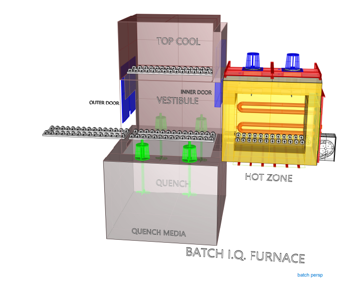
Last is going to be the material handling system. In the batch furnace, many have what we call a “rear handler.” We saw the cart and it would push the load into the vestibule, the inner door would open, and it would push the load into the furnace. It’s always preferable to push hot loads, not to pull on them. The reason is that the base trays are alloy and the compressive strength is much higher than the tensile strength is. If you’re pulling on loads, you’re going to break trays.
Once the load is in the furnace, you would have a rear handler so when the cycle is terminated and the inner door opens, you would have a mechanism — it may have a flat bar that’s half the width of the tray — that actually pushes the load into the quench vestibule.
There it’s pushed by the charge car and the inner door is open. That same handler, from the charge car, pushes it into the furnace. Now, when the cycle is terminated, there is a handler in the rear of the furnace that pushes it into the vestibule for quenching.
The exception is right here: When it’s taken out of the vestibule, typically the charge car goes in and grabs it and pulls it out. But, at that point, you’re at 100 or 200 degrees so, at that temperature, you have no material effect upon the strength of the alloy.
Doug Glenn: Okay, the motion it took it from the tray on the left inside is going to push it in and then the next step it’s also going to push it into this “hot zone,” correct?
Michael Mouilleseaux: Yes.
Doug Glenn: But what you’re saying is, when it’s coming out of the hot zone, there’s probably a mechanism on the far righthand side of the hot zone that’s going to push it back. Nothing is going in to pull it out because it’s hot.
Michael Mouilleseaux: Extended reach cars put the load into the vestibule and then put it into the hot zone.
There are some rear handlers that, rather than being a simple push function, have a dog mechanism that allows them to go and get the load in the vestibule and pull it into the furnace. Personally, I am not a fan of that; I like the extended reach car because when you’re pushing something, it is very easy to determine if you’ve put it in the right location. If you grab a load and pull it, you could lose the attachment on that load and then it’s not put exactly where you want it to be.
You can put amp meters on these things so that the amount of force that the motors require to pull in or push out a load. The one thing you need to be cognizant of is that it’s going to take more power — a higher amp draw — to push a 4000-pound load than it is a 2000-pound load. Once you understand what that is, you can monitor these furnaces and then they start making sense to you.
During the day-to-day operation of heat treat departments, many habits are formed and procedures followed that sometimes are done simply because that’s the way they’ve always been done. One of the great benefits of having a community of heat treaters is to challenge those habits and look at new ways of doing things. Heat TreatToday‘s 101 Heat TreatTips, tips and tricks that come from some of the industry’s foremost experts, were initially published in the FNA 2018 Special Print Edition, as a way to make the benefits of that community available to as many people as possible. This special edition is available in a digital format here.
Today, we begin an intermittent series of Technical Tuesday posts of the 101 tips by category, starting with Atmosphere Control.
Atmosphere Control
Heat TreatTip 5
Out of Control Carburizing? Try This 11-Step Test
When your carburizing atmosphere cannot be controlled, perform this test:
Empty the furnace of all work.
Heat to 1700°F (926°C).
Allow endo gas to continue.
Disable the CP setpoint control loop.
Set generator DP to +35°F (1.7°C).
Run a shim test.
The CP should settle out near 0.4% CP.
If CP settles out substantially lower and the CO2 and DP higher, there’s an oxidation leak, either air, water or CO2 from a leaking radiant tube.
If the leak is small the CP loop will compensate, resulting in more enriching gas usage than normal.
Sometimes but not always a leaking radiant tube can be found by isolating each tube.
To try and find a leaking radiant tube, not only the gas must be shut off but combustion air as well.
So you just ran a batch and the parts are bad. Now what? According to Jim Oakes at Super Systems Inc., here is a good checklist to use to start isolating the problem. While not exhaustive, this list can at least take you through a progression of steps to help start identifying the culprit.
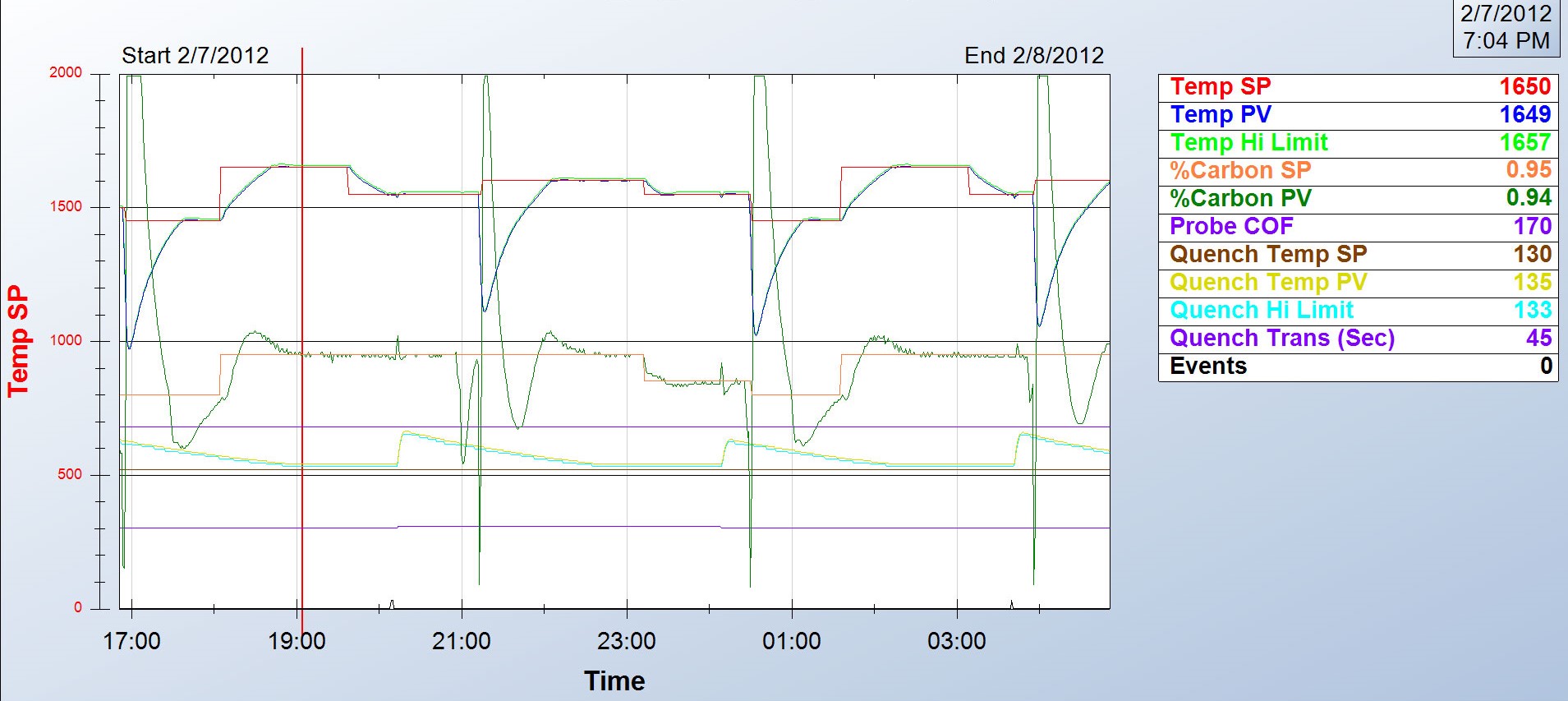
Step 1: Review the process data for abnormalities. Did the setpoint for temperature and atmosphere get set properly? Does the process chart show good control of the temperature and atmosphere? Was the time at heat correct? Was the quench and temper processes run properly?
Step 2: Check the generator to make sure it was pumping out the right atmosphere.
Step 3: Check the furnace atmosphere. Even if the generator is working, there may be leaks in the furnace.
Step 4: Check carbon controller to make sure it matches furnace atmosphere reading. Verify probe accuracy and adjust carbon controller.
Step 5: Do probe troubleshooting. And if all else fails . . .
Step 6: Replace the probe or call Super Systems for help.
Many factors can contribute to why parts are not meeting the correct hardness readings. According to Super Systems Inc., here is a quick checklist of how to start narrowing down the culprit:
Review process data for abnormalities: The first thing to do is make sure the parts were exposed to the right recipe. Check the recorders to make sure the temperature profile and atmosphere composition were correct. Make sure all fans and baffles were working correctly. Determine if any zones were out of scope and that quench times were acceptable. If any red flags appear, hunt down the culprit to see if it may have contributed to soft parts.
Check the generator. Next, check the generator to make sure it is producing the gas composition desired for the process. If available, check the recorders to make sure the gas composition was on target. If not, check the generator inputs and then the internal workings of the generator.
Check the furnace atmosphere. If the generator appears to be working correctly, the next step would be to check the furnace itself for atmosphere leaks. Depending on what type of furnace you have, common leak points will vary; for continuous furnaces, common leak points are a door, fan, T/C, or atmosphere inlet seals. Other sources of atmosphere contamination may be leaking water cooling lines in water-cooled jackets or water-cooled bearings. More than likely, if the generator is providing the correct atmosphere but parts are still soft, there is a leak into the furnace. This will often be accompanied by discolored parts.
Check carbon controller to make sure it matches furnace atmosphere reading (verify probe accuracy and adjust carbon controller). This can be done using a number of different methods: dew point, shim stock, carbon bar, 3 gas analysis, coil (resistance), etc. Each of these methods provides a verification of the furnace atmosphere which can be compared to the reading on the carbon controller. If the atmosphere on the carbon controller is higher than the reading on the alternate atmosphere check, that would indicate the amount of carbon available to the parts is not as perceived. The COF/PF on the carbon controller should be modified to adjust the carbon controller reading to the appropriate carbon atmosphere. If the reading is way off, it may require the probe to be replaced.
Configuring your atmosphere controller to ensure the correct carbon potential readings can sometimes be tricky. We suggest you double check your atmosphere control settings to make sure they are set up correctly. Before making a change to the carbon controller, make sure the atmosphere that the carbon probe and carbon controller are reading is matching up to an alternate method of atmosphere. This can be done using a number of different methods: dew point, shim stock, carbon bar, 3 gas analysis, coil (resistance), etc. Each of these methods provides a verification of the furnace atmosphere which can be compared to the reading on the carbon controller. The COF/PF on the carbon controller should be modified to adjust the carbon controller reading to the appropriate carbon atmosphere.
It is important to make sure that the alternate method of verifying atmosphere is done properly (sampling ports, time for atmosphere exposure, sample prep, etc).
The calculation of carbon in the atmosphere using a carbon/oxygen probe is based on the output millivolts — created based on the partial pressure of oxygen in the reference air versus partial pressure of oxygen in the furnace, the temperature of the furnace, and a calculation factor referred to as COF (CO Factor), PF (Process Factor), or Gas Factor.
The carbon controller can be modified so the COF/PF value can be changed to match up with the alternate reading. A furnace calculator on the SSI website or mobile app can help determine what these settings should be. It is important to note that you should not change these values to the point where you are masking another issue such as a bad probe or a furnace/generator issue.
Again, if the reading is way off (a setting of a COF below 130, for example), it may require the probe to be replaced.
If you’re having atmosphere problems with a furnace that has been operating normally for some time, avoid the temptation to remove the carbon probe. There are several tests you can run on nearly all carbon probes while the probe is still in the furnace, at temperature, in a reducing atmosphere. Super Systems Inc. provides an 11-step diagnostic procedure in a white paper on their website, in a paper titled, “Carbon Sensor Troubleshooting” by Stephen Thompson.
Atmosphere furnace pressure should be only slightly above ambient. The range should be between 0.25 – 0.35 inches water column. Higher pressures in multiple zone pusher furnaces will cause carbon control issues. High pressures in batch furnaces will cause high swings when doors and elevators move.
Wisdom dictates a trust-but-verify approach to your endothermic generator. Although your generator is supposed to crank out a consistent endo atmosphere, we suggest periodically verifying the integrity of that atmosphere with a dewpoint analyzer or a 3-gas analyzer. Generator control systems provide control of air gas ratio and possibly a trim system, used to maintain a dew point that could be rich (too much gas) or lean (too much air). The dew point range could typically be between 30°F and 50°F. Flowmeters are provided to maintain a base ratio (2.7 : 1) for the air/gas mixture supplied to a retort filled with nickel-coated catalyst. The gas is then passed through an air cooler (some older systems used water) to freeze the reaction so the gas can be transported through a header system to furnaces. The ratio at which the gas is generated offers a dew point that can be measured. The makeup of the endothermic gas provided by a generator is typically 40% hydrogen, 40% nitrogen, and 20% carbon monoxide. Maintaining these percentages will result in a carburizing atmosphere that is conducive to best carburizing practices.
Non-dispersive infrared analyzer (NDIR) systems are invaluable when trying to troubleshoot generator issues. The analyzer will typically measure CO, CO2, and CH4. As mentioned earlier, if we know that 20% CO is being generated, we can cross check the air/gas ratio and sticking flow meters, or determine that an adjustment of the air and/or gas ratio is required. The measurement for indication of sooted or nickel depleted catalyst can also be achieved by using an analyzer. If the indicated measurement of CH4 is higher than .5%, a burnout of the catalyst is required, using the manufacturer’s required procedures. If after a burnout the CH4 level is still high, the catalyst may need to be replaced altogether.
If you have any questions, feel free to contact the expert who submitted the Tip or contact Heat TreatToday directly. If you have a heat treat tip that you’d like to share, please send to the editor, and we’ll put it in the queue for our next Heat TreatTips issue.