AEROSPACE HEAT TREAT TECHNICAL CONTENT

CFC Fixturing — Sustainability Through Efficiency

Carbon fiber-reinforced carbon (CFC) fixtures significantly enhance sustainability in heat treatment by reducing material usage, lowering energy consumption, and enabling higher part loading with improved process efficiency. In this Technical Tuesday installment, Dr. Jorg Demmel, founder, owner, and president of High Temperature Concept, highlights how CFC delivers high dimensional stability, reduced distortion, and longer fixture life, resulting in better product quality, lower costs, and more ergonomic operations.

This informative piece was first released in Heat Treat Today’s May 2026 Sustainable Heat Treat Technologies print edition.


Introduction

Sustainability in industrial manufacturing is commonly defined as the ability to meet and present environmental, social, and economic needs without compromising those of future generations. Leveraging over 30 years of industry experience, the following article examines the role of carbon fiber-reinforced carbon (CFC) fixtures in heat treatment applications, including their impact on sustainability through increased efficiency, resource utilization, and performance.

This article expands on a previous two-part discussion of CFC fixtures (Heat Treat Today November 2022, March 2023) to focus on the main advantages of CFCs through a sustainability lens.

CFC Compared to Other High-Temperature Materials

Figure 1. Phasic diagram depicting “usable” strength over temperature change for many materials (Schröder 2022) | Image Credit: High Temperature Concept

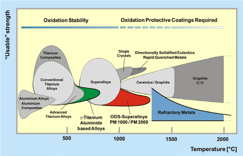
Figure 1 shows useable strength of high-temperature materials over temperature. From aluminum and aluminum alloys at the bottom left up to C/C (CFC), graphite and CFCs reach the highest “usable” strength of all materials at temperatures up to around 2000°C and higher.

Are CFC Fixtures Sustainable and Efficient?

Sustainability in the economical sense means using fewer resources per unit of output. This definition is directly related to efforts to increase efficiency across heat treatment processes.

To begin, it’s necessary to define heat treatment furnace fixtures and their main functions. Fixtures can be defined as follows (Demmel 2002):

  • Fixtures are manufacturing aids that are attached to workpieces and directly related to the work process. They serve to position and hold the workpieces.
  • They serve to bring workpieces into a working-ready position: to position them quickly, accurately, and as automatically as possible, and to hold and/or guide them in this position.

The main functions of CFC fixtures include:

  1. Force absorption and transmission: the weight of the workpieces as well as the handling and transportation forces.
  2. Defining interfaces: position/fastening of the fixture structure, connecting base grid, moving base and entire structure, position and locating the workpieces, support and limitation to the furnace, and ergonomics/weight for staff.
  3. Influence on heat treatment result: Good flowability through the fixture, good heating/cooling, no influence on atmosphere/media, no other interaction with workpieces as intended.
Figure 2. Specific strength of heat treatment fixture materials | Image Credit: High Temperature Concept

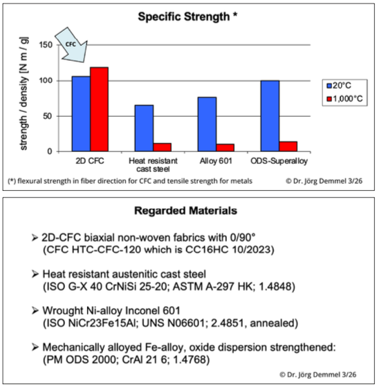
Figure 2 shows the “specific strength” defined as strength per density of four heat treatment fixture materials.

It can be observed that, especially at high temperatures greater than 1000°C (1832°F), the strength of CFC is 9 to 12 times greater than metal counterparts. This indicates that CFC fixtures need much less material to hold the same workpieces. In practice, fixture volume could be reduced up to 95% with certain high-end CFC, a drastic improvement in material savings.

Figure 3a-b. CFC trays in a monolithic design (left) and in a modular design (right)

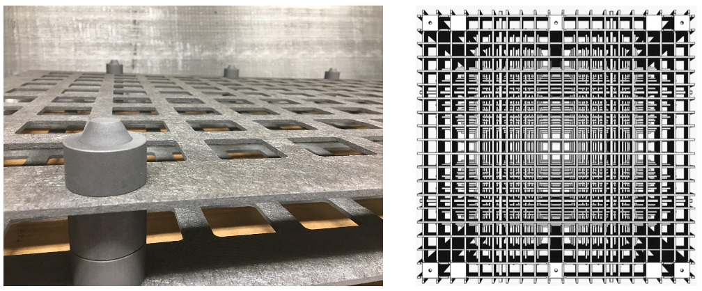
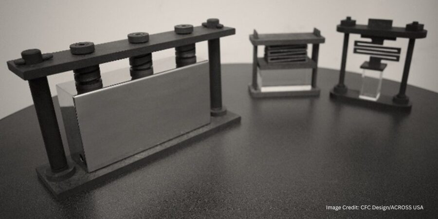
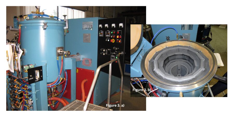
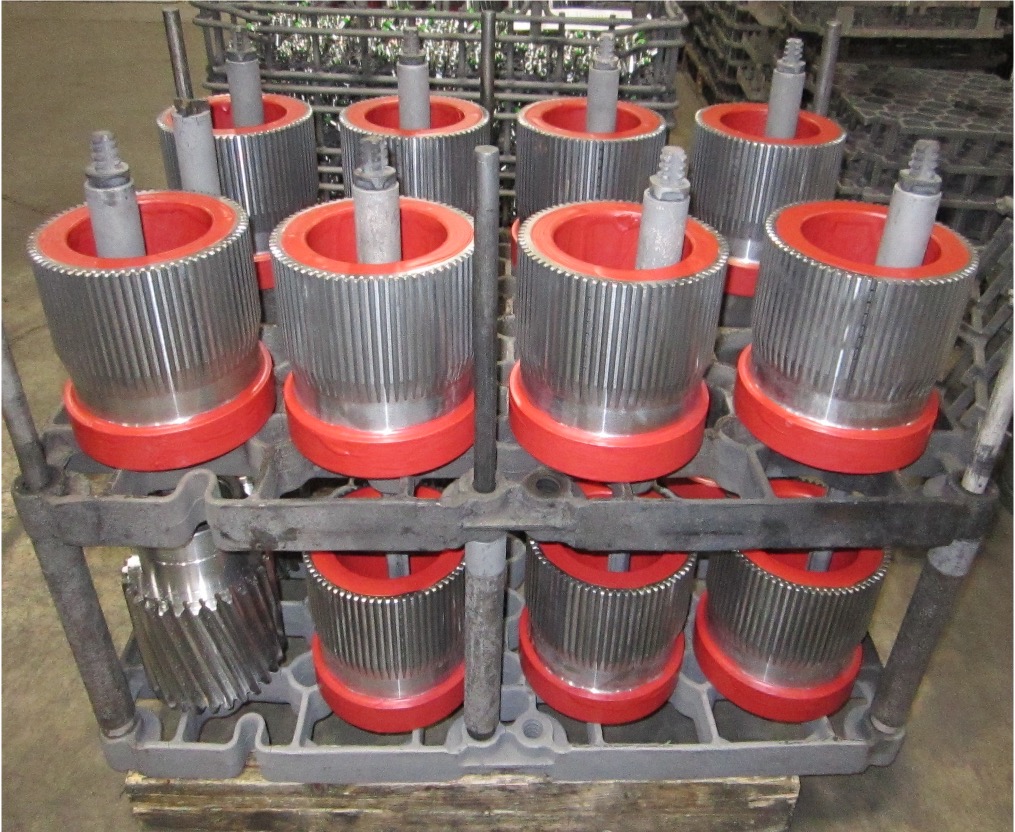
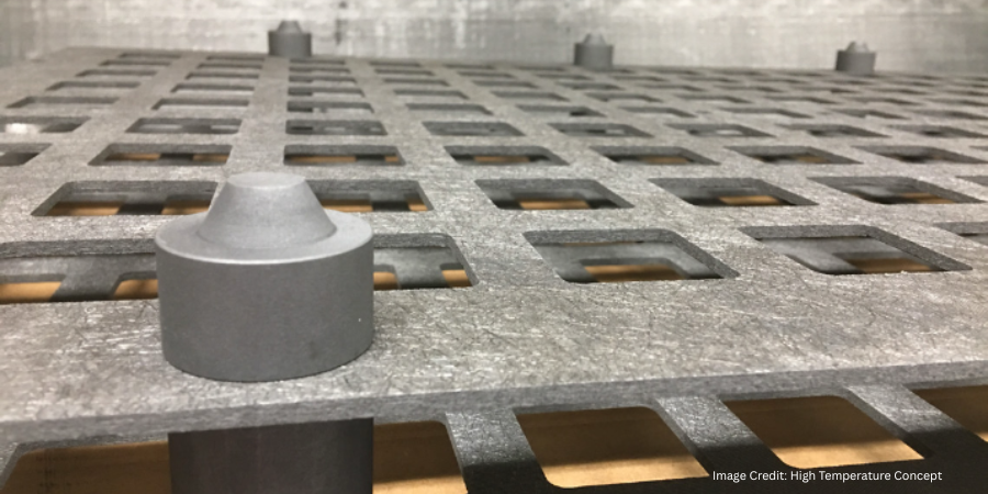
This effect for heat treatment fixtures is illustrated in Figure 3. It shows on the left a monolithic CFC tray for nitrocarburizing gear parts. The CFC plates are only around 5 mm (.5 in) thick, a width unachievable with steel or other metal alloys. Figure 3b is a top view “through” a four-level CFC rack with dimensions in length and width of 1,200 x 1,200 mm (47.2 x 47.2 in) for a net load of 1,340 kg (2,954 lb.) at maximum sintering vacuum process temperatures 1400°C (2552°F). Such an open design for best gas and heat transfer through the rack is impossible with racks made of steel or metal. The grid height used for that requirement is 60 mm (2.36 in).

Less fixture material usage means less energy consumption for the fixture and therefore a reduced pollution of the environment. Testing has shown that energy savings are around 60 to 80% for the fixture itself.

Figure 4. Before and after of fixture capacity improvement at Modine Europ (left); steel graphite racking (right) | Image Credit: High Temperature Concept

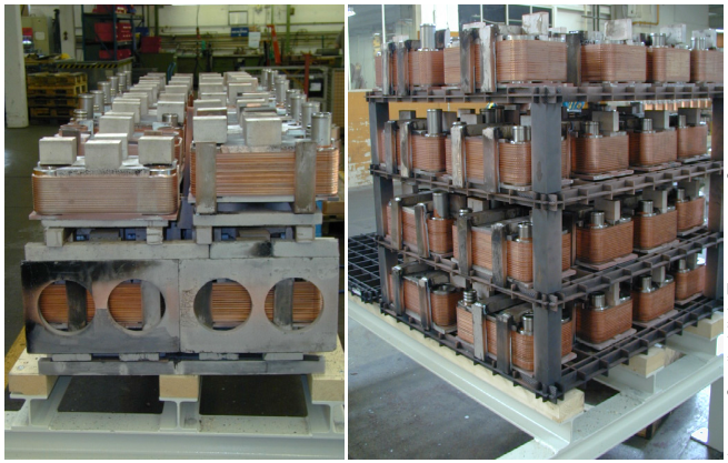
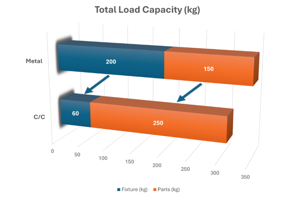
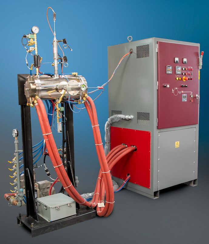
One of the most significant economic benefits of CFC fixtures compared to steel fixtures is the increase of part loading for each fixture of up to 100%. Figure 4 shows this comparison in racking heat exchangers for vacuum brazing at around 1120°C (2048°F). By using CFC fixtures with dimensions of 2,000 x 1,000 x 1,000 mm (78.74 x 39.37 x 39.37 in) for a total weight of up to 3,000 kg (6,614 lb.), furnace capacity roughly doubled. Additional results included:

  • Reduced fixture weight by 50%
  • Improved handling
  • Enhanced product quality
  • Reduced part costs by 15%
  • Reduced process time by 20%
  • Profitable in less than 1 year
Figure 5. Annealing of Allen keys at Wiha, Germany, with original fixturing (top) versus with updated CFC trays (bottom) | Image Credit: High Temperature Concept

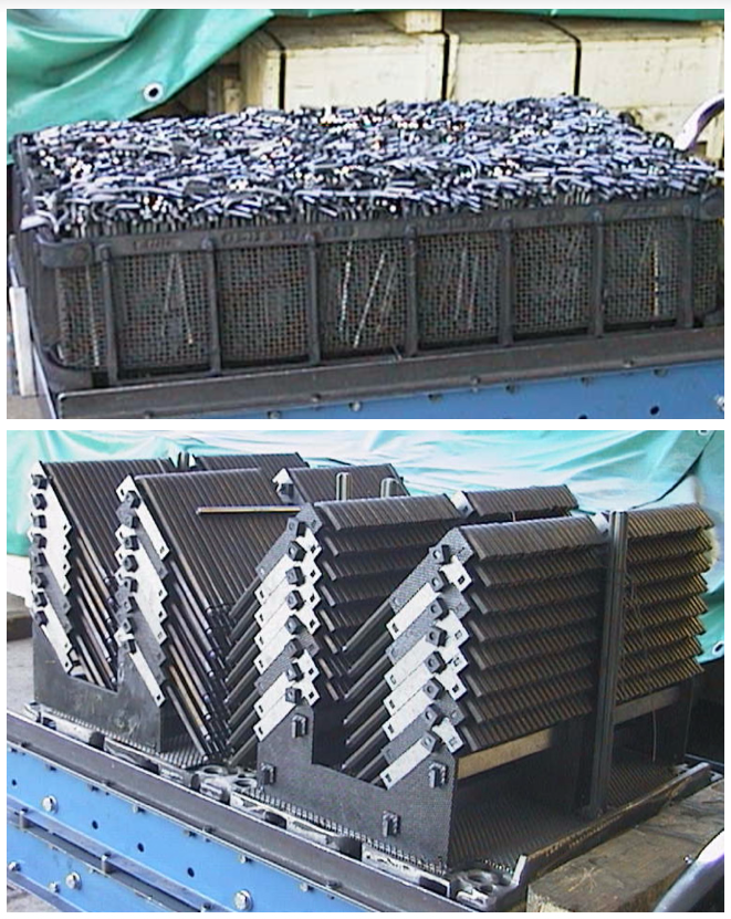
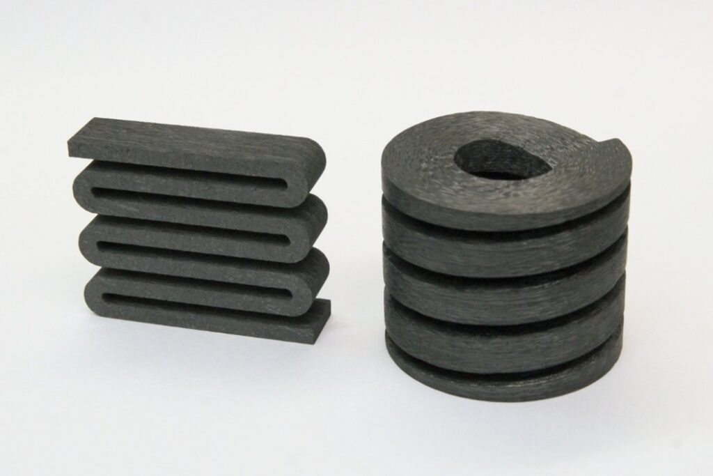
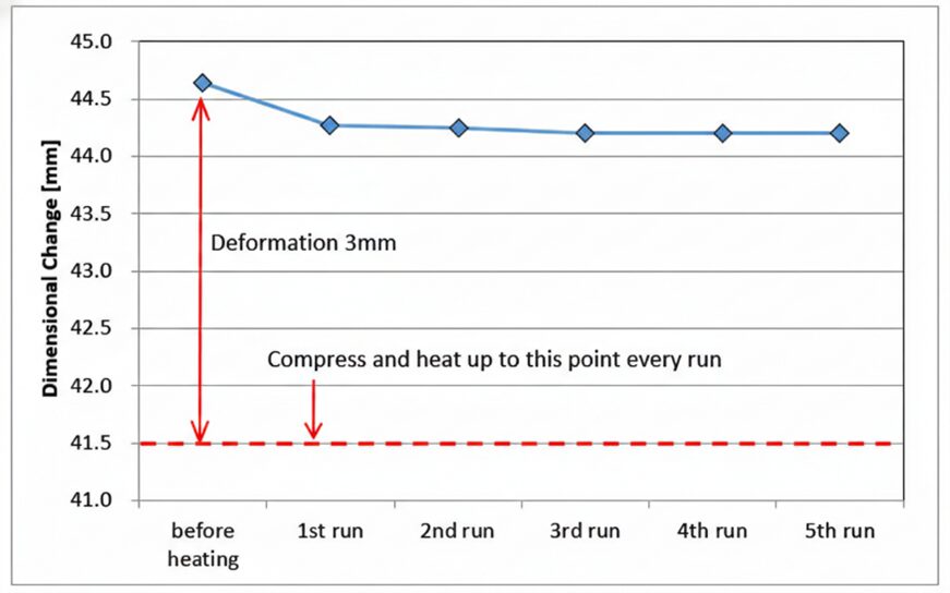
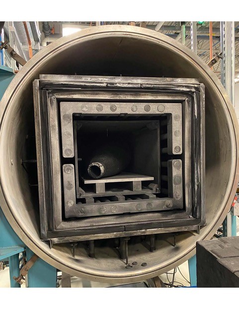
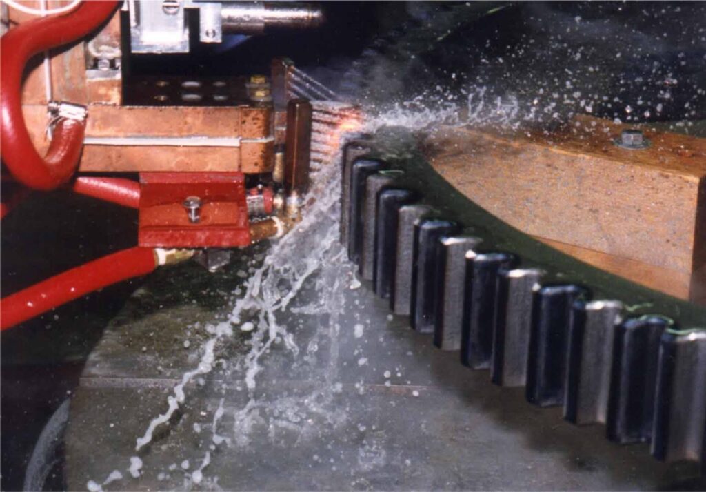
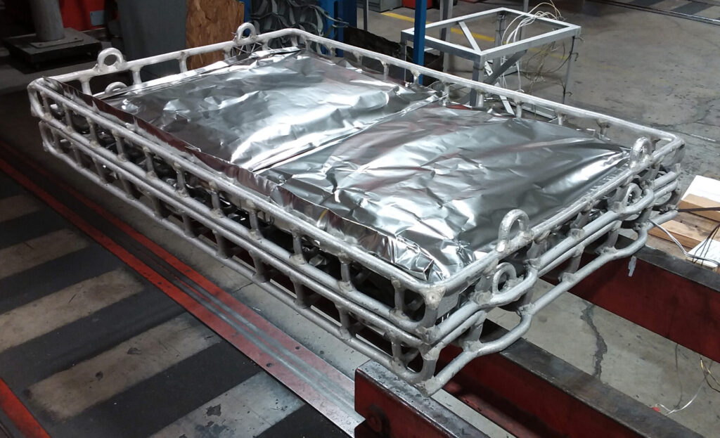
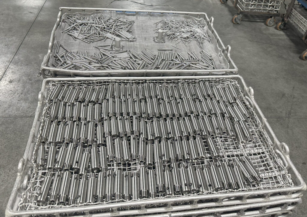
Another relevant application is in the case of oil quenching Allen keys at 870°C (1598°F) (Figure 5). In this process use case, casted steel baskets had been used. When CFC tray replaced these fixtures, an average 70% net load increase was realized. Additional results included:

  • Enhanced product quality — 90% less part distortion
  • Improved loading/unloading parts handling
  • Reduced part costs
  • Profitable within 1.5 years

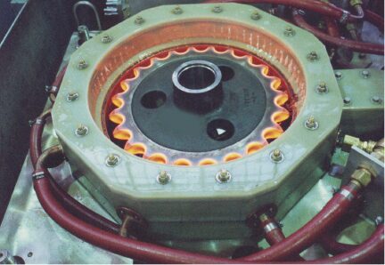
CFC fixtures offer high dimensional stability and retain their shape cycle after cycle. Parts loaded on CFC fixturing tend to have less distortion after processing. Therefore, very low dimensional change or distortion is the target for the heat treatment of parts like turbine blades, engine castings, engine stator rings, gear and transmission parts, and ceramic brake discs in the aerospace industry. Eliminating risks (e.g., decarburization, oxidation, and alpha case) is also critical.

Figure 6. CFC rack for titanium aerospace engine blades | Image Credit: High Temperature Concept

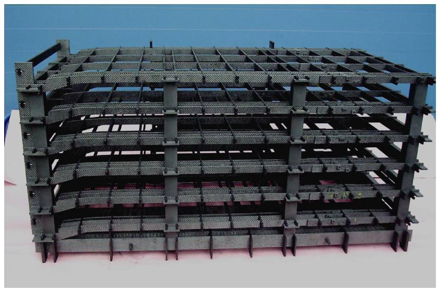
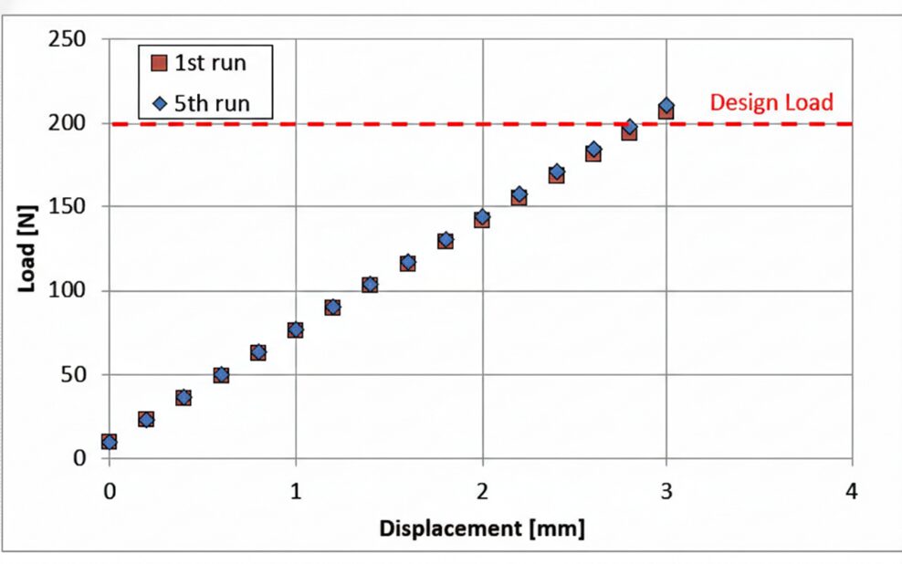
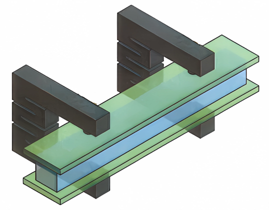
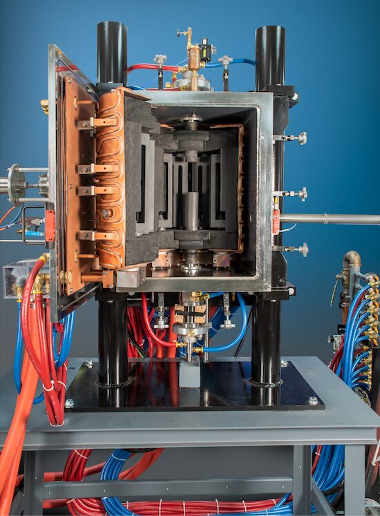
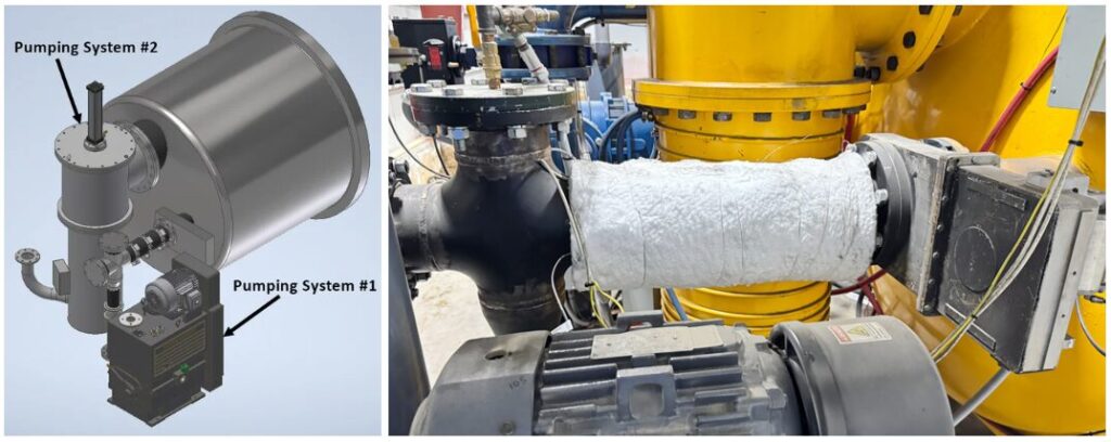
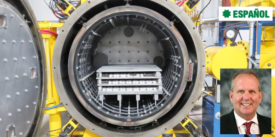
A third successful application is for hot isostatic pressing (HIPing) aerospace components. The first CFC custom fixture for HIPing titanium blades was built to reduce part distortion, hard machining, and rework (Figure 6). The fixture design is modular with high rigidity and high vertical openness to create a uniform heat transfer and argon gas flow and pressure. One special feature was the near net shape form of the grids, which conformed to the exact form of workpieces.

Conclusion

All three applications — brazing heat exchangers, annealing hand tools, and HIPing turbine blades — show that the higher the product quality and accuracy through a higher form and dimensional stability of the fixture and the workpieces, the more uniform the heat treatment process, allowing for less distortion and less rework of the parts. Avoiding the number one pitfall for heat treaters — inconsistent mechanical properties (Van Dyke 2025) — means realizing consistent mechanical part properties like hardness or toughness.

The use cases in this article show that the handling of the fixture and components in it (e.g., grids, trays, or posts) could be improved. Due to the light weight of CFC and a better design of the fixture itself, a more ergonomic fixture design helps reduce workload for employees. This is a social aspect, in that it improves the overall health of the employees.

Another important aspect to consider when investing in CFC is that these fixtures have very low and even zero CTE value (coefficient of thermal expansion) compared to all metal alternatives.

Because CFC is chemically inert in vacuum or protective atmospheres, has an excellent thermal shock resistance, and does not grow, creep, or age like metals, CFC fixtures run with more accuracy and stability in form and dimensions over many years, resulting in longer fixture life cycles (up to > 5 times). These characteristics make automatic workpiece and fixture handling possible (see use case in Tivnan 2026), resulting in better performance, higher savings, and more ergonomic workplaces for employees.

References

Deutsches Institut für Normung (DIN). 2017. Heat Treatment of Ferrous Materials—Terms and Definitions of Atmospheres. DIN 6300. Berlin: DIN.

Demmel, J. 2002. Material Scientific Aspects of the Development of New Fixtures for High Temperature Processes Made of Fiber-Composite Ceramics C/C and Other High Temperature Materials. Dissertation, Technical University Mining Academy Freiberg, Germany.

Verein Deutscher Ingenieure (VDI). 2019. Heat Treatment of Metallic Materials—Terms and Definitions of Atmospheres. VDI 6032. Düsseldorf: VDI.

Schröder, Johannes H. 2002. “New Application Possibilities for Dispersion-Strengthened Materials.” Paper presented at seminar Trends in High Temperature Processes, organized by J. Demmel, Fraunhofer Technology Development Group, Stuttgart, March 15.

Tivnan, Chris. “Optimized Heat Treat Results Start with Optimized Cleaning.” Heat Treat Today, April 2026.

Van Dyke, Ryan. 2025. “5 Heat Treating Pitfalls — And How to Avoid Them.” Heat Treat Today, July 2025.

About The Author:

Dr. Jorg Demmel
Founder, Owner, and President
High Temperature Concept

Dr. Jorg Demmel is the founder, owner, and president of High Temperature Concept. He received his Ph.D. in Engineering with a concentration in CFC fixtures, worked as a research associate at the Fraunhofer Society, and held various senior positions at Volkswagen before moving to the U.S. in 2018.

For more information: Contact Jorg Demmel at info@cfcfixtures.com.

CFC Fixturing — Sustainability Through Efficiency Read More »

C/C Composite Fixturing: Optimizing Precision Brazing for Aerospace Components

Advanced carbon-fiber-reinforced carbon (C/C) composites are redefining fixturing performance in high-temperature aerospace heat treating and furnace brazing. In this feature article, Hirotaka Nagao, Ph.D., technical expert at CFC Design Inc., explores how C/C composites maintain strength and dimensional stability at extreme temperatures while reducing fixture mass, improving thermal uniformity, and increasing furnace productivity.

This informative piece was first released in Heat Treat Today’s March 2026 Annual Aerospace Heat Treating print edition.


The Challenge of High-Temperature Integrity

In aerospace heat treating, and specifically furnace brazing, traditional metal fixturing often acts as a bottleneck for productivity. While stainless steel and super-alloys like Inconel or Hastelloy are common, they lose significant strength and begin to deform at temperatures above 700°C (1292°F), making them suspect for precision fixtures. For vacuum brazing processes involving aluminum and copper radiators or oil coolers, maintaining precise dimensional tolerance is a critical requirement for part performance and safety.

The emergence of carbon-fiber-reinforced carbon (C/C) composites offers a transformative solution, as these materials maintain high strength and rigidity at temperatures exceeding 2000°C (3632°F).

The Evolution of C/C Composites

C/C composites consist of high-strength carbon fibers reinforcing a carbon matrix, a combination that provides a unique set of mechanical properties. These materials first appeared in the 1960s and found practical use in specialized aerospace applications, such as spacecraft nose caps, wing leading edges, and aircraft brake materials by the 1980s. Historically, the cost of C/C composites limited their use to government-funded aerospace programs, but modern manufacturing advancements have brought the price range within the scope of general industrial applications.

Compared to graphite, C/C composites possess several times the strength and elastic modulus while offering far superior fracture resistance. Unlike traditional ceramics like silicon nitride or zirconia, which are vulnerable to thermal shock and can be fragile to handle, C/C composites offer high toughness and excellent resistance to radiation and corrosion.

While C/C composites offer exceptional thermal stability, their implementation requires careful management of specific material sensitivities. The primary concern is oxidation; in oxygen-rich environments, the material begins to degrade at temperatures exceeding 350°C (660°F), necessitating protective coatings or inert atmospheres. Furthermore, the initial capital investment for C/C components is significantly higher than that of graphite or standard metals, though this is typically balanced by their superior service life.

In high-temperature vacuum or atmosphere furnaces, direct contact between C/C composites and iron-containing metals must be avoided above 1000°C (1832°F) to prevent eutectic reactions; this is managed through physical separation or the application of barriers like boron nitride. Finally, for particulate-sensitive environments like semiconductor manufacturing, the inherent tendency of C/C composites to produce carbon dust is mitigated by applying specialized carbon coatings to seal the surface.

Figure 1. Comparison of total load capacity of C/C fixture and metal fixture | Image Credit: CFC Design/ACROSS USA

Material Performance: A Technical Comparison

The decision to switch from metal or ceramic to C/C composites involves a detailed understanding of the thermal and mechanical limits of each material class.

  • Heat-resistant alloys: Maximum service temperatures for standard heat-resistant alloys are often capped at 400°C (752°F) before mechanical properties degrade.
  • Super-alloys: Even advanced materials like Inconel and Hastelloy lose significant strength and suffer from permanent deformation above 700°C (1292°F), rendering them ineffective as springs or precision supports in high-heat environments.
  • Ceramics: While they offer high heat resistance, ceramics are vulnerable to thermal shock and can break when repeatedly cycled at temperatures exceeding 1000°C (1832°F). They also lack the toughness required for heavy industrial handling.
  • C/C composites: Advanced materials that combine carbon fibers with a carbon matrix offer an exceptional balance of lightweight strength and thermal resilience. These materials maintain their characteristics and mechanical strength from room temperature up to 2000°C (3632°F).

Structural Advantages of C/C Composite Fixtures

A primary advantage of C/C precision braze fixturing is the drastic reduction in “gross weight” within the furnace, which directly impacts the economics of the heat treat cycle.

  • Mass reduction: C/C material is approximately 20% the weight of metal, which drastically reduces the dead weight the furnace must heat.
  • Increased capacity: In a specific industrial application, C/C fixtures weighing 66 kg (145 lb) replaced 200 kg (440 lb) stainless-steel fixtures.
  • Loading efficiency: In a furnace with a 350 kg (772 lb) total load capacity, this weight reduction allowed the “parts weight” to increase from 150 kg to 250 kg per cycle — a 66% increase in productivity.
  • Productivity gains: The ratio of total fixture weight to total load capacity was reduced by 70%, enabling more components to be processed in a single cycle.
  • Energy efficiency: Reducing the fixture weight lowers the total heat capacity of the load, allowing for faster heating times and a drastic reduction in the cost of energy per part.

Thermal Uniformity and Defect Reduction

Traditional metal fixtures often require supplementary “dead weights” to apply constant pressure during the brazing process. These weights, which can reach 20 kg or more, introduce significant thermal challenges:

  • Thermal shadowing: Large metal weights tend to block radiant heat waves, creating “shadows” that compromise heating uniformity.
  • Defect rates: Inconsistent heating leads to defective brazed parts and necessitates spacing parts further apart to ensure uniformity, which further limits productivity.
  • C/C solution: The compact design of C/C fixtures, combined with lightweight springs (weighing only 70 grams), eliminates these thermal barriers. This allows for a decrease in the defect rate and an increase in total process quantity.

The Physics of C/C Spring Technology

To replace heavy dead weights, engineers utilize C/C spring technology to apply a constant load throughout the heating cycle. These springs maintain their force as temperature increases, and the brazing begins once the melting point of the filler metal is reached.

1. Continuous Fiber Coil Springs

Figure 2. (left) New Z-type plate spring innovated for mass production and (right) continuous fiber coil spring

Modern C/C coil springs are manufactured such that the long carbon fibers are spirally continuous and not segmented during the machining process. Early C/C composite coil springs were fabricated by cutting shapes out of two-dimensionally reinforced long-fiber C/C blocks. This method had a significant drawback: the reinforcing fibers were segmented during processing. Because the fibers were cut, the material could not exhibit its full structural strength, leading to a decrease in the spring constant after repeated use in high-temperature environments.

To compensate for these limitations, a proprietary spring type was developed using long carbon fibers that are spirally continuous in one direction (Figure 2). Because these fibers are not segmented, they fully demonstrate their role as a reinforcing medium, resulting in a product that maintains a stable spring constant even after repeated cycles exceeding 1000°C (1832°F).

  • Durability: Because the reinforcing fibers are not cut, the spring fully demonstrates its strength and maintains a stable spring constant even after repeated use.
  • Performance: A single carbon spring can generate up to 24.5 kg of force while weighing only 26–84 grams. This provides an equivalent load to metal weights that are hundreds of times heavier.

2. New Type C/C Composite Spring: “Z-Type” Spring

While continuous-fiber coil springs are highly effective, they possess inherent manufacturing disadvantages. Neatly arranging long fibers in a spiral shape is complex and difficult to scale for mass production. Furthermore, because the spring size depends on specific mold dimensions, it has historically been difficult to produce a diverse variety of spring strengths and sizes.

To address the mass-production limitations and molding size constraints of coil-shaped springs, the “Z-type” plate spring was engineered to support large loads using a more efficient manufacturing process (Figure 2). Instead of a coiled architecture, this spring is fabricated in a zig-zag, serpentine pattern using a C/C composite plate.

  • Material design: The zig-zag pattern is achieved by using laminated plates where short carbon fibers are randomly oriented in a two-dimensional XY plane.
  • Shear modulus: This random orientation dramatically improves the in-plane shear modulus, allowing the Z-spring to support larger loads and offer a larger deflection allowance than coil-shaped versions.
  • Stability: In repeated load tests at 1250°C (2282°F), Z-type springs show a minimal 1% decrease in natural length during the first run and zero “setting” or deformation in subsequent cycles.
  • Mass production: Unlike coil springs, Z-type springs can be mass produced through water-jet machining from large C/C laminate plates.

Figure 3 shows the displacement-load curve of the Z-type C/C composite spring. From this figure, satisfactory spring characteristics are exhibited, even in repeated load tests.

Figure 3. Displacement-load curve of the Z-type C/C composite spring | Image Credit: CFC Design/ACROSS USA
Figure 4. Z-type C/C composite spring dimensions after heating and subsequent heating runs | Image Credit: CFC Design/ACROSS USA

After heating the Z-type C/C composite spring in a compressed state at 1250°C (2282°F) for 30 minutes in a nitrogen atmosphere, spring characteristics were measured at room temperature and a repeated heating test was performed.

A decrease of about 1% in the natural length was observed only during the first heating run. However, the natural length did not change even if the heating was repeated after, and it was found that there was no setting at all.

Compared to coil-type C/C composite springs, C/C composite springs made from short-fiber reinforcing materials are characterized by very few shape restrictions and various configurations are achievable.

Advanced Applications: Clips, Bolts, and Large-Scale Fixtures

Figure 5. C/C clips in a sandwich arrangement. This design enables load application while bypassing the need for intricate custom fixture. | Image Credit: CFC Design/ACROSS USA

The versatility of C/C machining allows for specialized components that simplify complex furnace operations:

  • C/C clips: Developed to simplify fixturing, these clips act as integrated springs that sandwich parts directly, eliminating the need for complicated, heavy clamp structures.
  • Thermal expansion absorption: In high-temperature furnaces, graphite heaters can deform under their own weight or fail due to thermal stress at joint points. C/C bolts with a “notched” design act as integrated springs to absorb dimensional changes caused by thermal expansion, preventing damage to electrodes and joints.
  • Large-scale serpentine springs: Z-springs can be manufactured in large serpentine shapes, achieving deflections of up to 22% of their natural length (e.g., a 50 mm deflection on a 230 mm spring) while maintaining satisfactory spring characteristics.

Improving Plant Economics

The transition from heavy metal fixturing to high-performance C/C composites is no longer just a technical preference but a necessity for modern plant economics. For aerospace components that demand zero-distortion and high-precision brazing, C/C fixturing provides the thermal and mechanical stability required for 21st-century manufacturing.

About The Author:

Hirotaka Nagao, Ph.D., is a technical expert at CFC Design Inc. specializing in the development of advanced carbon-fiber-reinforced carbon (C/C) composite materials. With a doctorate in material science, his research focuses on high-temperature applications and improving production efficiency through innovative C/C fixture and spring designs for furnace brazing and heat treatment environments.

For more information: Contact ACROSS USA at www.acrosscc.com.

C/C Composite Fixturing: Optimizing Precision Brazing for Aerospace Components Read More »

Hypersonics Come Alive with Vacuum and Controlled Atmosphere Furnaces

Hypersonic vehicles and missiles operating at Mach 5 and beyond place unprecedented thermal and environmental demands on aerospace materials. In this Technical Tuesday installment, Scott Robinson, product manager of ceramics and powder metallurgy at Centorr Vacuum Industries, examines how vacuum and controlled-atmosphere furnaces support the research, prototyping, and production of ultrahigh-temperature ceramics, carbon–carbon composites, and other advanced materials used in hypersonic applications.

This informative piece was first released in Heat Treat Today’s March 2026 Annual Aerospace Heat Treating print edition.


Introduction

Hypersonic missiles and vehicles are an emerging class of aerospace technology that is developing rapidly toward active use in military and potentially commercial applications. These machines can achieve sustained speeds of Mach 5 or greater within the Earth’s atmosphere (i.e., at altitudes below about 90 km). While conventional intercontinental ballistic missiles can also achieve hypersonic speeds during atmospheric reentry, they follow a high-arching ballistic trajectory with limited maneuverability, in contrast to the real-time in-flight maneuverability offered by hypersonic systems. As such, military actors prefer hypersonic missiles for precision strikes (Mesa 2024), while in the commercial realm, airliners are excited by the possibility of drastically shortened journey durations with hypersonic vehicles (TomorrowDesk 2025).

Because hypersonic missiles and vehicles move at extreme speeds within Earth’s atmosphere, they are subject to significant atmospheric compression and friction effects (Smith 2021). These effects result in considerable aerodynamic heating of the leading edges, nose tips, and exhaust-washed structures, from 1800°C (3200°F) to more than 3000°C (5400°F).

Traditional aerospace materials such as aluminum, stainless steel, and titanium cannot be used at these elevated temperatures without thermal protection engineering. In contrast, an emerging portfolio of materials including refractory metals, carbon-carbon composites, ultrahigh-temperature ceramics (UHTCs), and ceramic matrix composites (CMCs) can more easily deal with this extreme heat.

UHTCs and CMC materials typically are composed of metal carbides, borides, and nitrides, which means they are traditionally processed at very high temperatures. Currently, the leading candidate materials are silicon carbide (melting/decomposition point: 2730°C, or 4945°F) and zirconium diboride (melting point: ~3246°C, or 5875°F) due in part to their reasonable raw material costs.

Processing of UHTCs, CMCs, and other advanced materials for aerospace applications includes one or more of the following high-temperature processing steps, often using vacuum and controlled atmosphere furnace technology:

  • Chemical vapor infiltration
  • Chemical vapor deposition
  • High-temperature sintering
  • Graphitization
  • Silicon melt infiltration of carbon-carbon composites

Each stage of the product development cycle — from laboratory-scale research and development to prototype development to production-scale manufacturing — requires a portfolio of specialized furnaces to achieve the goals of each stage.

This article takes a closer look at the types of furnace solutions available to develop, process, and commercialize these high-performance materials.

Laboratory-Scale Research and Development


Figure 1. a) Centorr Vacuum Industries’ LF 3000°C (5400°F) graphite vacuum furnace and b) top view of hot zone; 3” x 4” (75 x 100 mm; Ø x h) hot zone. | Image Credit: Centorr Vacuum Industries

Laboratory-scale R&D activities focus mostly on the development, fabrication, and testing of small-scale parts, which require a small, adaptable furnace.

The LF graphite vacuum furnace is an example of the type of furnaces needed for small-scale parts (Figure 1). First designed in 2012, it is a robust, low-cost development furnace with temperature capability up to 3000°C (5400°F) in vacuum or inert gas. This temperature range covers most hypersonic, UHTC, and other applications. For example, current users fit the small 3″ x 4″ (75 x 100 mm; Ø x h) hot zone with small graphite crucibles to fire graphite-based powders for applications in battery and electric vehicle technology.

In another case, Dalhousie University in Nova Scotia, Canada, a research-based university, modified the base LF system by adding a small binder/off-gassing trap and positive pressure exhaust tower for processing of non-oxide ceramics produced by additive manufacturing. These samples include silicon-based ceramics (silicon carbide and silicon nitride), high-entropy ceramics, and cermet systems.

Subsequent laboratory applications require a larger hot zone furnace for processing bigger samples. One example of this type of furnace is the Series 10 graphite tube furnace (Figure 2). This tube furnace is based on a more than 50-year-old furnace design, although the traditional alumina or quartz tube has since been replaced with a solid graphite tube. Operating in vacuum or partial/positive pressures of argon, R&D centers use this furnace to process carbon powder formulations to maximize the percent conversion to graphite, as not all carbon-based starting materials will convert to crystalline graphite.

Figure 2. Series 10 3000°C (5400°F) graphite tube furnace; 4″ x 16″ (100 mm x 400 mm) hot zone diameter and height. Image Credit: Centorr Vacuum Industries

Figure 3. a) Series 45 graphite top-loading furnace and b) top view of hot zone. Used for carbon/graphite work, this model offers a larger useable firing footprint at higher temperatures than the Series 10 furnace. The hot zone diameter and height dimensions approximate 6″ x 6″ (150 mm x 150 mm), and temperature is rated for 3200°C (5790°F). | Image Credit: Centorr Vacuum Industries

As R&D activities begin to focus on particular material compositions, larger furnaces are needed to synthesize meaningful sizes and quantities of candidate materials prior to scaling up for manufacture, like the Series 45 graphite top-loading furnace (Figure 3).

Characterization and Prototyping Stage


Figure 4. Front view of the Series TT Testorr graphite hot zone rated for 2700°C (4890°F) processing temperatures | Image Credit: Centorr Vacuum Industries

Once the final candidate materials are processed, aerospace design engineers need to test meaningfully sized samples of the materials at high temperature under mechanical loading. It is best to have a furnace that can be combined with mechanical test stands to take measurements of mechanical properties. This is the case for Wichita State University’s National Institute for Aviation Research, which leverages multiple Testorr® furnace units to measure tension, compression, and shear properties of ceramic matrix composites, refractory metals, and other materials at high temperature. Rated for temperatures up to 2700°C (4890°F) in vacuum or inert gas, the furnace can better simulate some aspects of hypersonic service environments (Figure 4).

An important task of the R&D and prototyping stages is to work out processing parameters that will be translated to production-scale manufacturing processes. For example, simple carbon structures will react with air during reentry and suffer damaging effects at temperatures as low as 500°C (930°F). Therefore, any carbon-carbon materials or solid carbon shapes used in hypersonic applications must be protected with advanced ceramic coatings for durability and oxidation resistance.

Chemical vapor deposition is one such coating deposition process, and one of the most popular protective coatings is silicon carbide. The coating is deposited on substrate parts by flowing hydrogen gas through a bubbler of liquid methyltrichlorosilane (MTS; CH3SiCl3) gas. Newer systems use a heated evaporator to vaporize the MTS liquid in a hydrogen carrier gas stream. The combination of hydrogen and MTS is introduced at partial pressures into the furnace hot zone inside a graphite retort, where the gases “crack” or decompose, depositing microns-thick coatings of silicon carbide onto the part’s surface.

Production Stage

Once the advanced materials are properly characterized and prototyped, it is time to look at equipment for full-scale production manufacturing. The furnace configurations for these processes can be conventional front-loading designs or may be oriented in vertical top- or bottom-loading designs for floor space savings and gas flow dynamics.


Figure 5. Production-size Sintervac vacuum furnace for processing carbon-carbon melt infiltration composite materials | Image Credit: Centorr Vacuum Industries

The Sintervac® front-loading graphite furnace (Figure 5) has integral graphite retort and dual gas flow to the main chamber and retort. These furnace systems include durable rotary piston pumping systems with inline binder traps and particulate filters to protect the pumping systems from damage from abrasive ceramic particulates. The internal graphite retort compartmentalizes the off-gassing that takes place and prevents it from escaping into the hot zone, where the oxide byproducts can attack and degrade the graphite heating elements and rigid graphite board insulation.

One common application for this type of furnace is melt infiltration of carbon-carbon composites to improve the physical properties and oxidation resistance of the composite. When processed in partial pressures (or even at positive pressures) of argon, silicon will melt at approximately 1450°C (2640°F). The silicon liquid and vapor infiltrate into the void spaces of the porous carbon-carbon composite via capillary action. The infiltrated silicon reacts with the free carbon in the carbon-carbon fiber structure, forming a silicon carbide matrix around the carbon-carbon fiber structure.

Firms like Exothermics (Amherst, NH) use this process for missile and aerospace applications. The silicon carbide matrix structure provides an environmental barrier to oxidation during reentry into Earth’s atmosphere and improves the matrix’s temperature performance to approximately 1600°C (2910°F) in air.

Smaller production units were also developed for carbon-carbon work at temperatures from 2450°C and 2600°C (4440°F and 4710°F). The addition of dedicated water-cooled filtration traps and 10-μ particulate filters helps deal with the heavy off-gassing expected from processing of carbon-carbon materials.

In contrast to melt infiltration, chemical vapor infiltration drives gaseous reactants into the porous matrix where the gas reacts with the porous structure to form a dense matrix. The chemical vapor infiltration process is used to fabricate larger parts for hypersonic applications, such as rocket motors and missile components, and carbon-carbon aircraft brakes. Vertical top- and bottom-loading chemical vapor infiltration units like the example in Figure 6 can be used for these types of applications.


Figure 6. Series 4300 vacuum furnace for chemical vapor infiltration and graphitization. The furnace may be built in a top-loading or bottom-loading configuration; the unit scales from 52″ to 80″ (1,320 mm to 2,000 mm) in diameter and heights from 80″ up to 120″ (2.0 to 3.0 meters). | Image Credit: Centorr Vacuum Industries

In the chemical vapor infiltration process, gases, including hydrogen, methane, and propane, are fed into the furnace chamber at high flow rates and at temperatures approaching 1000°C–1100°C (1830°F–2010°F). The methane and propane gases break down and deposit carbon deep into the matrix of the carbon-carbon fibrous parts. These cycles can be very long, approaching seven to ten days, for the material to fully densify, and multiple cycles are usually necessary.

Low operating pressures require extremely large mechanical pumping systems with large vacuum blowers or boosters. These furnaces include water-cooled “tar” traps (with a heated stripping system) and large Dollinger particulate filters for handling the resin off-gas byproducts.

These furnaces are almost always induction heated, using multizone induction coils and large, thick-wall graphite susceptors for optimal temperature uniformity. The insulation design uses carbon black powder, which is economical and highly efficient for temperature reduction.

While more conventional rigid or flexible graphite board or felt materials can be used, Centorr’s experience has shown that the degree of infiltration of carbon resins over time will affect the density and porosity of the insulation pack (as it does the load material), causing degradation and densification of the insulation. The denser insulation results in high coil water temperatures, which compromises hot zone life. Specialized carbon black installation and removal equipment is required by the end-user to maintain the insulation efficiency of the furnace hot zone. Because gas flow in the furnace is critically important, special diffusor plates or plenums are used to uniformly direct gas flow across the entire geometry of the parts.

Once the advanced materials undergo chemical vapor infiltration, they are still composed of a carbon base material, which needs to be converted to a more orderly crystalline graphite structure to impart the durability and strength required in aerospace applications. To accomplish this conversion, the material needs to be heated at temperatures greater than 2300°C (4170°F), a process called graphitization.

The graphitization process employs similar furnace designs to the chemical vapor infiltration process, but the induction heating power supply is changed to the more conventional single zone coil, and the vacuum pumping systems are smaller with no tar traps needed. Load sizes of 3,000–5,000 lb. (1,360–2,268 kgs) are possible. Both the smaller and larger chemical vapor infiltration and graphitization units have large, water-cooled heat exchangers inline with large cooling fans, which reduce cooling times from ten or more days to less than 175 hours.


Figure 7. a) Series 3800 bottom-loading silicon carbide chemical vapor deposition furnace. b) Series 3800 chemical vapor deposition furnace hot zone with multizone control; 53″ diameter x 83″ height (1,350 mm x 2,108 mm) graphite hot zone furnace rated for 1600°C (2910°F) operation. | Image Credit: Centorr Vacuum Industries

A smaller graphitization unit was also developed in a 30″ diameter x 40″ height (76 mm x 1,000 mm) size rated to 2900°C (5250°F) maximum temperature in a vertical bottom-loading configuration for processing smaller parts in lower volumes for aerospace brakes.

The silicon carbide chemical vapor deposition units for laboratory applications discussed previously are also needed for production-size volumes (Figure 7). Due to tight temperature uniformity requirements, these units are multizone control with graphite hot zones constructed of rigid graphite board for process durability. The pumping systems can be either “dry” or “liquid ring” designs for processing the acidic off-gas materials. A post-exhaust chemical scrubber system is required to safely neutralize the hydrogen chloride off-gases.

Enabling the Next Generation of Aerospace Materials

The difficult design requirements of next-generation aerospace technologies will continue to push the existing limits of material performance. As characterization and development of new materials will be critical to the success of these aerospace programs, vacuum and controlled atmosphere furnaces will play an essential role in the production of such materials.

References

American Elements. n.d.a “Silicon Carbide Data Sheet.” https://www.americanelements.com/silicon-carbide-409-21-2.

American Elements. n.d.b “Zirconium Diboride Data Sheet.” https://www.americanelements.com/zirconium-diboride-12045-64-6.

Mesa, J. 2024. “What’s the Difference Between a Hypersonic Missile and ICBM?” Newsweek, November 21, 2024. https://www.newsweek.com/difference-between-icbm-irbm-missiles-1989780.

Smith, C. R. 2021. “Aerodynamic Heating in Hypersonic Flows.” Physics Today 74 (11): 66–67.

TomorrowDesk. 2025. “Hyperian Aerospace and the Dawn of Hypersonic Flight.” TomorrowDesk, March 29, 2025. https://tomorrowdesk.com/evolution/hyperian-aerospace-hypersonic-flight.

Heat Treat Today thanks the American Ceramic Society for allowing us to print this piece. This article was originally published in ACerS Bulletin, September 2025.

About The Author:

Scott K. Robinson
Product Manager of Ceramics and Powder Metallurgy
Centorr Vacuum Industries

Scott K. Robinson is product manager of ceramics and powder metallurgy at Centorr Vacuum Industries (Nashua, NH).

For more information: Contact Scott Robinson at srobinson@centorr.com.

Hypersonics Come Alive with Vacuum and Controlled Atmosphere Furnaces Read More »

Ask The Heat Treat Doctor®: Why and How Do We Heat Treat Gears? Part Two

Ask The Heat Treat Doctor® has returned to bring sage advice to Heat Treat Today readers and to answer your questions about heat treating, brazing, sintering, and other types of thermal treatments as well as questions on metallurgy, equipment, and process-related issues. In this installment, Dan Herring continues his discussion on gear heat treatment, exploring vacuum and induction hardening methods for gears — from low-pressure carburizing for advanced materials to single shot and tooth-by-tooth induction techniques — and how each can be matched to the specific demands of any gear application.

This informative piece was first released in Heat Treat Today’s March 2026 Annual Aerospace Heat Treating print edition.


In Part One of this discussion (Air & Atmospheres Heat Treating, February 2026), we discussed various gear types, materials, and how they can be atmosphere heat treated. This month, we are focusing on vacuum and induction heat treating methods. Let’s learn more.

Vacuum Heat Treatment Processing Methods

Table A. Advanced Materials Processed by LPC

Vacuum processing can be used for most of the atmosphere treatments mentioned in Part One including carburizing (Figure 1). Low pressure carburizing (LPC) is a proven technology and the choice for many advanced applications in aerospace, automotive, off-highway, and motorsports markets, as well as the development of carburizing cycles for high-performance materials (Table A).

Figure 1. Typical commercial heat treat load of gears for vacuum carburizing (Otto and Herring 2007) | Image Credit: Photo courtesy of Midwest Thermal-Vac
Figure 2. Pyrowear 675 – LPC – anneal – double normalize – harden – anneal – deep freeze – double temper | Image Credit: The HERRING GROUP, Inc.

The range of effective case depths for most of these grades can range up to 2.0–3.0 mm (0.080–0.120 inches) without significant sacrifice of microstructure (Figure 2). Furnace variables, such as temperature uniformity (± 3°C or ± 5°F), control of cycle parameters (boost/diffuse times, gas flow rate, pressure, hydrocarbon type) and surface carbon optimize the microstructure, producing case uniformities of ± 0.05 mm (± 0.002 inches). Where permitted, the range of carburizing temperatures now includes the use of high temperature (> 980°C, or 1800°F) techniques.

All these advanced materials required extensive development testing to produce custom designed recipes to optimize cycle parameters. Also, quenching methods (Otto and Herring 2002) have improved, allowing us to achieve desired core properties with quenching parameter selection (high-pressure gas or oil) for distortion-sensitive and distortion-prone part geometries (Otto and Herring 2005, 2008).

Induction Hardening Methods

Various methods of hardening via applied energy are used in manufacturing gears, including flame hardening, laser surface hardening, and induction hardening.

Of the various types of applied energy processing, induction hardening is the most common. Induction heating is a process that uses alternating electrical current that induces a magnetic field, causing the surface of the gear teeth to heat. The area is then quenched resulting in an increase in hardness within the heated area. This process is typically accomplished in a relatively short time. The final desired gear performance characteristics are determined not only by the hardness profile and stresses but also by the steel composition and prior microstructure. External spur and helical gears, bevel and worm gears, racks, and sprockets are commonly induction hardened. Typical gear steels include AISI/SAE grades 1050, 1060, 1144, 4140, 4150, 4350, 5150, and 8650.

Figure 3. Patterns produced by induction hardening (Rudnev 2000)

The hardness pattern produced by induction heating (Figure 3) is a function of the type and shape of inductor used, as well as the heating method. Quenching or rapidly cooling the workpiece can be accomplished by spray or submerged quench. The media typically used for the quench is a water-based polymer. The severity of this quenchant can be controlled by the polymer’s concentration. Cooling rates are usually somewhere in between what would be obtained from pure water and oil. In some unusual situations compressed air or nitrogen is used to quench the part.

The most common methods for hardening gears and sprockets are by single shot (Figure 4) or the tooth-by-tooth method (Figure 5). Single shot often requires large kW power supplies but results in short heat/quench times and higher production rates. This technique uses a circumferential copper inductor, which will harden the teeth from the tips downward.

Figure 4. Typical single shot induction hardening operation | Image Credit: Photo courtesy of Ajax-Tocco-Magnethermic
Figure 5. Tooth-by-tooth induction hardening of a helical gear | Image Credit: Photo courtesy of Ajax-Tocco-Magnethermic

The larger and heavier loaded gears (where pitting, spalling, tooth fatigue, and endurance are issues) need a hardness pattern that is more profiled like those produced by carburizing, which can be obtained by tooth-by-tooth hardening. This method is limited to gear tooth sizes with modulus 4.23–5.08 (6 or 5 DP) using frequencies from 2 to 10 kHz and about 2.54 (10 DP) using a range of 25 to 50 kHz.

The lower the frequency, the deeper the case depth. Tooth-by-tooth hardening is a slow process and usually reserved for gears and sprockets that are too large to single shot due to power constraints. The process involves heating the root area and side flanks simultaneously, while cooling each side of the adjacent tooth to prevent temper-back on the backside of each tooth. The induction system moves the coil at a pre-programmed rate along the length of the gear. The coil progressively heats the entire length of the gear segment while a quench follower immediately cools the previously heated area. The distance from the coil to the tooth is known as coupling or air gap. Any changes in this distance can yield variation in case depth, hardness, and tooth distortion. The gear is indexed after each tooth has been hardened, often skipping a tooth. This requires at least two full revolutions in the process to complete the hardening of all teeth. Straight, spur, and helical gears up to 5.5 m (210 inches) weighing 6,800 kg (15,000 lb) have been processed with this method. The entire process yields a repeatable soft tip of the tooth with hard root and flank. In other applications, the tip and both flanks can be hardened simultaneously and yield a soft root.

In Summary

Today’s design engineer has the good fortune of being able to choose from a number of heat treatment technologies for any given type of gear material and design. When selecting a gear hardening method, it is essential to specify not only the desired mechanical and metallurgical properties, but the critical dimensions that must be held and even the desired stress state of the gears themselves. The secret to success is understanding the advantages and limitations of each technology and taking these into consideration when determining the overall cost of gear manufacturing.

References

Herring, Daniel H. 2004a. “Gear Heat Treatment: The Influence of Materials and Geometry.” Gear Technology, March/April.

Herring, Daniel H. 2004b. “Reducing Distortion in Heat-Treated Gears.” Gear Solutions, June.

Herring, Daniel H. 2007a. “Oil Quenching Technologies for Gears.” With Steven D. Balme. Gear Solutions, July.

Herring, Daniel H. 2007b. “Heat Treating Heavy Duty Gears.” With Gerald D. Lindell. Gear Solutions, October.

Herring, Daniel H. 2012–2016. Vacuum Heat Treatment. Vols. 1–2. BNP Media Group.

Herring, Daniel H. 2014–2015. Atmosphere Heat Treatment. Vols. 1–2. BNP Media Group.

Herring, Daniel H., Gerald D. Lindell, D. J. Breuer, and B. Matlock. 2001. “Atmosphere vs. Vacuum Carburizing.” Heat Treating Progress, November.

Herring, Daniel H., Gerald D. Lindell, D. J. Breuer, and B. Matlock. 2002. “An Evaluation of Atmosphere and Vacuum Carburizing Methods for the Heat Treatment of Gears.” In Off-Highway Conference Proceedings. SAE International.

Otto, Frederick J., and Daniel H. Herring. 2002a. “Gear Heat Treatment: Today and Tomorrow, Part 1.” Heat Treating Progress, June.

Otto, Frederick J., and Daniel H. Herring. 2002b. “Gear Heat Treatment: Today and Tomorrow, Part 2.” Heat Treating Progress, July/August.

Otto, Frederick J., and Daniel H. Herring. 2005. “Vacuum Carburizing of Aerospace and Automotive Materials.” Heat Treating Progress, January/February.

Otto, Frederick J., and Daniel H. Herring. 2007. “Advancements in Precision Carburizing of Aerospace and Motorsports Materials.” Heat Treating Progress, May/June.

Otto, Frederick J., and Daniel H. Herring. 2008. “Improvements in Dimensional Control of Heat Treated Gears.” Gear Solutions, June.

Rudnev, V. 2000. “Gear Heat Treating by Induction.” Gear Technology, March/April.

About the Author

Dan Herring
“The Heat Treat Doctor”
The HERRING GROUP, Inc.

Dan Herring has been in the industry for over 50 years and has gained vast experience in fields that include materials science, engineering, metallurgy, new product research, and many other areas. He is the author of six books and over 700 technical articles.

For more information: Contact Dan at dherring@heat-treat-doctor.com.

For more information about Dan’s books: see his page at the Heat Treat Store.


Ask The Heat Treat Doctor®: Why and How Do We Heat Treat Gears? Part Two Read More »

Heat Treatment of Carbon and Graphite-Based Materials for Space Travel and Exploration

Carbon and graphite-based materials are among the few engineered materials capable of withstanding the extreme thermal, mechanical, and environmental demands of space travel. In this Technical Tuesday installment, Kimberly Thompson, technology manager at Morgan Advanced Materials, examines how carefully controlled heat treatment directly governs the structure, purity, and performance of these materials and emphasizes the importance of furnace design, atmosphere control, and temperature precision required to achieve reliable properties for aerospace and space exploration applications.

This informative piece was first released in Heat Treat Today’s March 2026 Annual Aerospace Heat Treating print edition.


Space travel presents one of the most extreme operating environments encountered by engineered materials. Launch, orbital operation, atmospheric reentry, and deep space exposure all impose combinations of extreme temperature, rapid thermal cycling, oxidative attack, mechanical stress, and radiation. Among the limited class of materials capable of performing in these challenging conditions, carbon and graphite-based materials have played a critical role for decades, continuing to enable and innovate modern space exploration.

From carbon ablatives, which play a crucial role in heat shields and propulsion systems, to structural graphite components and ultra-pure graphitic elements, carbon materials are uniquely suited to survive and perform in extreme temperature regimes that exceed the limits of metals and ceramics. The performance of these graphite/graphite-like materials is directly linked to the heat treatment (aka graphitization) and processing steps used during their manufacture. The relationship between processing conditions and final product performance is driven by the technical foundations for heat treating carbon and graphite materials for space travel through the conversion, graphitization, and purification steps.

Carbon Materials in Space Applications

Carbon-based materials, such as those produced by the Performance Carbon division of Morgan Advanced Materials (see Figures 1-3), have a long history of being utilized in spaceflight systems due to their exceptional thermal stability, low density and mass, and resistance to thermal shock. Common applications include:

  • Ablative thermal protection systems for atmospheric re-entry
  • Nozzle throats and rocket motor components
  • High temperature insulation and support
  • Structural graphite parts
  • Ultra-pure graphitic components for sensitive electronic or propulsion systems

The performance outcomes required in these applications are diverse but share common demands: survivability at extreme temperature exceeding 2000°C (3630°F) and down to -270°C (-450°F), predictable thermal behavior, low outgassing, and controlled erosion or sublimation rates. Achieving these characteristics relies heavily on heat treatment processing conducted through both low and high temperatures.

Figure 1. Carbon cloth | Image Credit: Morgan Advanced Materials
Figure 2. Felted rayon billets | Image Credit: Morgan Advanced Materials
Figure 3. Rayon felt | Image Credit: Morgan Advanced Materials

As the material is heat treated and temperatures increase, the carbon structure will undergo progressive stabilization. Precursor conversion or pre-carbonization will occur during low temperature thermal processing. Fundamental transformation will occur as the disordered carbon structure reorganizes into graphitic planes through realignment of aromatic carbon layers. The planes become progressively ordered in the presence of elevated temperatures, increasing crystallographic alignment. The transition from carbon to graphite is gradual and highly reliant on heat treatment process capability to maintain thermal uniformity throughout all process stages.

The extent of graphitization is typically tailored to meet specific application requirements, as carbon and graphite structures each offer distinct performance advantages. In certain applications, a predominately carbon structure is preferred due to its higher bulk density and superior mechanical strength as compared to graphite. These characteristics can be advantageous in space applications where structural integrity, load bearing capability, or erosion resistance under mechanical stress are primary concerns. However, carbon materials generally exhibit slightly lower carbon yield and may experience higher erosion or mass loss when exposed to extreme thermal flux or oxidative stress.

In contrast, materials processed to a graphitic structure offer enhanced thermal stability at elevated temperatures, improved resistance to thermal shock, and reduced impurity content due to high temperature volatilization of contamination. Graphite materials typically demonstrate superior performance in applications requiring sustained exposure to ultra high temperature or rapid thermal cycling. This benefit, however, is often accompanied by lower density and reduced mechanical strength relative to their carbon counterparts, which can limit their use in mechanically demanding roles.

Ultimately, the selection of a carbon- or graphite-based structure involves balancing thermal performance, mechanical requirements, erosion behavior, and environmental exposure. Heat treatment parameters must be carefully engineered to achieve the desired degree of structural ordering, ensuring that the final material delivers optimal performance for its intended spaceflight application.

Low Temperature Thermal Processing

Most engineered carbon precursors, such as cellulose, phenolic resin, acrylic (polyacrylonitrile), or pitch-based materials, require conversion into carbon through a sequence of controlled thermal processes. The first conversion process is considered low temperature in terms of graphite processing. During this process, hydrogen, oxygen, and nitrogen content decreases, volatile species are driven off, and the aromatic carbon structures begin to form. The thermal processing profile through this low temperature conversion is critical. Careful control of heat treatment parameters, tailored to the material system, supports uniform carbon conversion and minimizes defects as the foundational microstructure is established.

At these processing temperatures, a wide range of conventional heat treatment equipment can be effectively used. Because the operating temperatures remain below the limits of most metallic alloys, furnaces equipped with metal-based heating elements, structural components, and containment systems are generally suitable for this phase of processing. Additionally, these furnaces may be configured as batch or continuous systems, depending on part geometry, production volume, and process control requirements. Heat input is achieved through established industrial thermal processing approaches, with system selection guided by requirements for temperature uniformity, process control, and operational considerations. Regardless of the configuration, the selected furnace must be capable of maintaining stable inert or reducing atmospheres to prevent oxidation of the carbon precursor during thermal decomposition.

Successful low temperature processing demands a strong foundational understanding of carbonization mechanisms combined with sound materials science principles. As organic precursors are heated, complex chemical reactions occur that result in the formation of increasingly ordered carbon structures. The heating rate and soak durations must be carefully engineered to accommodate these reactions while minimizing internal stresses, distortion, or excessive porosity. Improper ramp rates or insufficient soak times can result in non-uniform shrinkage and irreversible defects that propagate through later processing stages.

Equally critical is the furnace’s ability to execute the programmed temperature profile with a high degree of precision and repeatability. Accurate control of heating ramps, dwell temperatures, and cooling rates is essential, as even modest deviations can alter the evolving microstructure of the material. Temperature overshoot, uncontrolled gradients, or localized hot spots can lead to uneven carbon yield, variations in density, and inconsistent mechanical or thermal properties in the final product. Consistency of temperature accuracy within the furnace ensures that the entire product load processes uniformly, reducing variation in the material to allow for uncompromised performance in demanding aerospace applications.

High Temperature Thermal Processing

Materials that have completed precursor conversion or pre-carbonization are subsequently subjected to high temperature thermal processing to complete carbonization or to initiate and advance graphitization, thereby establishing the final material structure and properties. Although the carbon microstructure continues to evolve significantly during this stage, the material experiences minimal additional mass loss, shrinkage, or chemical decomposition compared to earlier processing stages. Most volatile species have already been removed, resulting in a comparatively stable structure that is less susceptible to distortion, cracking, or dimensional change. As a result, parts processed in this temperature regime typically exhibit improved dimensional stability and reduced sensitivity to heating rates when compared to low-temperature carbonization operations.

High-temperature processing can be conducted at temperatures well above the lower temperature processing. At these elevated temperatures, the available furnace technologies become significantly limited. Conventional metal or ceramic based furnace systems are no longer suitable due to material degradation, contamination risk, and structural instability under these conditions. Instead, furnaces designed for high-temperature carbon and graphite processing are typically induction or resistance (i.e., vacuum furnace) heated and constructed primarily from graphite-based components.

These furnace systems are specifically engineered to withstand extreme temperatures while maintaining thermal uniformity and chemical compatibility with the carbon materials being processed. The use of graphite heating elements, insulation, and structural components minimizes contamination and allows operation in inert or controlled atmospheres required for carbon and graphite processing.

As relatively little chemical decomposition occurs during this phase, high-temperature processing cycles can often be completed more rapidly than low-temperature carbonization cycles. Additionally, moderate temperature variations within the furnace are less likely to produce significant variability in final material properties. However, precise temperature control remains critical, as the peak temperature achieved during processing largely determines the degree of carbonization or graphitization and, consequently, the final microstructure and performance characteristics of the material.

Continuous monitoring and accurate measurement of operating temperatures are therefore essential. Even small deviations in maximum temperature can lead to meaningful differences in crystallinity, density, thermal conductivity, and mechanical behavior. For space applications, where consistency and reliability are paramount, ensuring that each component reaches the intended peak temperature is a defining requirement of high-temperature thermal processing. As space missions continue to demand materials capable of performing in the most extreme environments, advanced heat treatment remains a critical enabler of reliability and innovation.

About The Author:

Kimberly Thompson
Technology Manager
Morgan Advanced Materials

Kimberly Thompson holds a bachelor’s degree in chemical engineering from Purdue University and a master’s degree in materials engineering from Auburn University. With nearly nine years with Morgan Advanced Materials, she currently serves as technology manager leading new product development and has spent six years as the technical resource for rayon-based carbon and graphite materials supporting space industry applications.

For more information: Contact Kimberly Thompson at Kimberly.Thompson@morganplc.com.

Heat Treatment of Carbon and Graphite-Based Materials for Space Travel and Exploration Read More »

IN 718 Part 2: Heat Treatment

Today’s Technical Tuesday highlights the second installment in a multi-part series by Nikolai Alexander and The Heat Treat Doctor® Daniel H. Herring, diving into the controlled heat treatment strategies required to unlock IN 718’s exceptional high-temperature strength, toughness, and corrosion resistance. From solution annealing and duplex aging to hot isostatic pressing and additive manufacturing considerations, the authors explore how precise process control and equipment selection directly shape microstructure and performance in critical applications.

This informative piece is from Heat Treat Today’s March 2026 Annual Aerospace Heat Treating print edition. For part 1 on the history, production, and general applications, read Heat Treat Today’s February 2026 Annual Air & Atmosphere Heat Treating print edition.


Introduction

IN 718 was developed for and is extensively used in the aerospace industry. Today, the superalloy and its modifications are heavily relied upon, including IN 718Plus® (US Patent No. 6.730.264 B2), which is designed for operating service temperature to 705°C (1300°F), approximately 55°C (100°F) above that of IN 718. (IN 718Plus will be the subject of a future article by the authors). This article reviews the heat treatment of IN 718 and the need to control both equipment and process variability. Also discussed is the method of additive manufacturing (AM) to produce component parts and the heat treat challenges it poses, including the need to HIP (hot isostatically press) the material to achieve maximum property benefits.

Heat Treatment of IN 718

Figure 1. Typical vacuum furnace used for heat treating IN 718 | Image Credit: Solar Manufacturing

IN 718 is typically heat treated in a vacuum furnace given that it is a sensitive alloy and easily oxidized. Processing in an all-metal shielded furnace (Figure 1) offers advantages for keeping the parts bright after the aging process, without the need to wrap them.

Graphite-lined vacuum furnaces, often with molybdenum heating elements, can also be used provided appropriate precautions are taken. The furnace must be extremely leak tight with a rate of rise under 5 microns Hg per hour. Processing in vacuum is typically done in the 10⁻⁵ torr range. Argon as a partial pressure or cooling gas is necessary to avoid nitriding or oxidation. An alternative, albeit older technology, approach is the use of a vacuum-purged argon atmosphere box furnace with a retort.

From a metallurgical perspective, the amount, morphology, and distribution of the delta (δ) phase have a great influence on the properties of IN 718. During heat treatment, delta phase is extremely important for optimizing mechanical properties, particularly at high temperatures to control migration and precipitation in IN 718. The delta phase inhibits grain growth (by pinning the grain boundaries) and enhances creep and fatigue performance. However, excessive or poorly controlled precipitation is detrimental to other properties like ductility and fracture toughness.

Optimization of delta phase distribution includes selecting the proper solutionizing temperature, between 980–1040°C (1800–1900°F) depending primarily on nickel content, where the delta phase is stable (and thus precipitates out). Thermomechanical working can also achieve this effect by forming more globular-shaped particles rather than acicular (needle-like) ones (Guan, et al. 2023).

There are a number of heat treatments that can be performed on IN 718, including stress relief, homogenizing, solution annealing, precipitation hardening (aka aging), and HIP.

Stress Relief

Stress relief is typically performed at the mill and is a compromise between the amount of residual stress one would like to remove and the possibly harmful effects to both high temperature properties and corrosion resistance. For wrought alloys, stress relief at full annealing temperature is recommended since intermediate temperatures might cause aging. Hold times are one hour per inch of section thickness. For castings, stress relief is especially important when dealing with complex shapes, which may be prone to cracking in subsequent operations or when dimensional control is important.

Homogenization

Homogenization heat treatment is applied to IN 718 for the uniform distribution of alloying elements and dissolution of detrimental phases after its processing through casting and additive manufacturing (AM) routes. There is a definite relationship between laves phase fraction (i.e., the brittle intermetallic compound formed due to niobium segregation during solidification) and homogenization time at various temperatures 1140–1170°C (2085–2140°F). With an increase in homogenization temperature, the time required for dissolution of laves phase and reduction in laves phase fraction reduces drastically. Also, at a given temperature the reduction in laves phase fraction has been shown to occur with the increase of time (Eliasen and Somers 2010).

Full Annealing

Figure 2. Full annealing of IN 718 alloy bars | Image Credit: Solar Atmospheres, Inc.

The process of full annealing involves complete recrystallization and dilution of all or most of the secondary phases to reach maximum softness (Figure 2).

The process is typically run at 955°C (1750°F) holding one hour per inch of cross-sectional area. If welding is to be performed on the component, annealing should be performed immediately after the welding operation. It is noteworthy that niobium additions help overcome cracking problems during welding.

Solution Annealing

Solution annealing (aka solution heat treating) is designed to dissolve secondary phases to prepare the alloy for age hardening and produce maximum corrosion resistance. An added benefit is homogenization of the microstructure.

Figure 3. Standard heat treatment cycle of IN 718 | Image Credit: Polasani and Dabhade 2024

A typical heat treatment of IN 718 involves a two-step process — solution heat treating and then age hardening — to control the mechanical property response of the material (Figure 3).

For bar stock, a typical cycle might involve solution annealing at 955°C (1750°F) followed by a 2-bar quench under argon or nitrogen (which can be used if post machining will be performed). This is followed by duplex aging at 730°C (1350°F) for eight hours followed by a vacuum or rapid cool to avoid surface reactions (such as oxidation) and (depending on whether further precipitation is needed) to 650°C (1150°F) and another hold for eight hours followed by a gas fan quench.

Solution annealing at 925–1010°C (1700–1850°F) with its corresponding aging treatment is considered the optimum heat treatment for IN 718, where a combination of rupture life, notch rupture life, and rupture ductility is of greatest concern. The highest room-temperature tensile and yield strengths are also associated with this treatment. In addition, because of the fine grain developed, it produces the highest fatigue strength (Herring 2019).

By contrast, solution annealing at 1040–1065°C (1900–1950°F) with its corresponding aging treatment is the treatment preferred in tensile-limited applications because it produces the best transverse ductility in heavy sections, impact strength, and low-temperature notch tensile strength. However, this treatment tends to produce notch brittleness in stress rupture (Herring 2019).

Aging/Duplex Aging

Figure 4. Duplex aging of IN 718 land-based turbine rods | Image Credit: Solar Atmospheres, Inc.

The aging process is designed to strengthen the material, forming precipitates from the supersaturated solid solution mastic from the solution annealing step.

Duplex aging (Figure 4) involves a two-step heat treatment process and on IN 718 is performed around 730°C (1350°F) for eight hours followed by a vacuum cool or in some cases a rapid cool to avoid surface reactions (such as oxidation) and (depending on whether further precipitation is needed) down to 620°C (1150°F) and another hold for eight hours. This is followed by a gas fan quench. The first soak temperature is intended to initiate precipitation of phases influencing strength and hardness properties. The second soak temperature further refines the microstructure and optimizes the material’s properties based on the phases developed in the initial aging and cooling stages.

Hot Isostatic Pressing

Figure 5. Typical HIP furnace capable of high temperature/pressure | Image Credit: AVS Inc.

Hot isostatic pressing (HIP) combines high pressure and high temperature to influence the density and microstructure of IN 718 (Figure 5). It is critically important to improve the mechanical strength of shape cast and additive manufactured components to homogenize the as-built microstructure and minimize variation in mechanical properties. It helps to eliminate residual stresses, close pores, close cracks and ensures the material is properly fused (Shipley 2023).

For example, it has been reported (Lee, et al. 2006) that four hours at 2155°F (1180°C) under a pressure of 25.5 ksi (175 MPa) is optimal to improve the microstructure (grain size and segregation) along with tensile properties of IN 718 castings.

Future Outlook

Additive manufacturing (AM) of IN 718 (and superalloys in general) is becoming an increasingly important method for component part manufacturing. It allows complex 3D shapes to be formed without the difficulties inherent in casting, forming, and machining of these alloys.

Electron beam-powder bed fusion (E-PBF) and laser-beam powder bed fusion (L-PBF) have shown great promise for processing IN 718 and other nickel-based superalloys. An absolutely necessary, if not critical, step in the process is post-HIP to heal cracks and homogenize the microstructure.

Heat treating will continue to play an important role in enhancing the properties of IN 718. It will be necessary to update the standard heat treatment requirements (e.g., AMS5662 and AMS5663) to incorporate powder metallurgy (PM) and AM technologies to optimize properties for components made by these methods.

More investigation is needed to optimize solutionizing and aging temperatures for modified IN 718 chemistries. For example, the effect of the cooling rate after aging treatments on the precipitate size and morphology and subsequent mechanical properties of the alloy must be explored in more detail (Eliasen and Somers 2010). And from a heat treatment perspective there is interest in case hardening (nitriding, low-temperature carburizing) of IN 718 (Sharghi-Moshtaghin, et al. 2010, Eliasen and Somers 2010).

Finally, AM processes rely on layer-upon-layer melting. As such, modeling, sensor technology, process temperature monitoring and control of surface displacement improve the build. Emerging trends suggest that the integration of machine learning and artificial intelligence for real-time quality control and process optimization will be a key part of the manufacturing strategy moving forward (Babu, et al. 2018).

References

Akca, Enes, and Gursel, Ali. 2015. “A Review on Superalloys and IN718 Nickel-Based INCONEL Superalloy.” Periodicals of Engineering and Natural Sciences 3 (1): 15–27.

ASM International. 2016. ASM Handbook, Volume 4E: Heat Treating of Nonferrous Alloys. ASM International.

Babu, S. S., N. Raghavan, J. Raplee, S. J. Foster, C. Frederick, M. Haines, R. Dinwiddie, M. K. Kirka, A. Plotkowski, Y. Lee, and R. R. Dehoff. 2018. “Additive Manufacturing of Nickel Superalloys: Opportunities for Innovation and Challenges Related to Qualification.” The Minerals, Metals & Materials Society and ASM International: 3764–3780.

Bradley, Elihu F., ed. 1988. Superalloys: A Technical Guide. ASM International.

del Bosque, Antonio, Fernández-Arias, Pablo, and Vergara, Diego. 2025. “Advances in the Additive Manufacturing of Superalloys.” Journal of Manufacturing and Materials Processing 9 (215): 1–31.

Chandler, Harry, ed. 1996. Heat Treater’s Guide: Practices and Procedures for Nonferrous Alloys. ASM International.

Croft Systems. n.d. “The Difference between a Wellhead & Christmas Tree.” https://www.croftsystems.net/oil-gas-blog/the-difference-between-a-wellhead-christmas-tree/.

Decker, R. F. 2006. “The Evolution of Wrought Age-Hardenable Superalloy.” Journal of The Minerals, Metals & Materials Society, September: 32–36.

Eliasen, K. M., T. L. Christiansen, and M. A. J. Somers. 2010. “Low-Temperature Gaseous Nitriding of Ni-Based Superalloys.” Surface Engineering 26 (4): 248–255.

Guan, Hao, Wenxiang Jiang, Junxia Lu, Yuefie Zhang, and Ze Zhang. 2023. “Precipitation of δ Phase in Inconel 718 Superalloy: The Role of Grain Boundary and Plastic Deformation.” Materials Today Communications 36 (August).

Herring, Daniel H. 2011. “Stress Corrosion Cracking.” Industrial Heating, October: 22–24.

Herring, Daniel H. 2012. Vacuum Heat Treating: Principles, Practices, Applications. BNP Media II, LLC.

Herring, Daniel H. 2019. “The Heat Treatment of Inconel 718.” Industrial Heating, June: 12–14.

Lee, Gang Ho, Ang Ho, Minha Park, Byoungkoo Kim, Jong Bae Jeon, Sanghoon Noh, and Byung Jun Kim. 2023. “Evaluation of Precipitation Phase and Mechanical Properties According to Aging Heat Treatment Temperature of Inconel 718.” Journal of Materials Research and Technology 27 (Nov–Dec): 4157–4168. https://doi.org/10.1016/j.jmrt.2023.10.196.

Lee, Shin-Chin, Shih-Hsien Chang, Tzu-Piao Tang, Hsin-Hung Ho, and Jhewn-Kuang Chen. 2006. “Improvements in the Microstructure and Tensile Properties of Inconel 718 Superalloy by HIP Treatment.” Materials Transactions 47 (11): 2877–2881.

Loria, Edward A. 1988. “The Status and Prospects of Alloy 718.” Journal of Materials, July: 36–41.

Polasani, Ajay, and Vikram V. Dabhade. 2024. “Heat Treatments of Inconel 718 Nickel-Based Superalloy: A Review.” Metals and Materials International: 1204–1231.

Sharghi-Moshtaghin, Reza, Harold Kahn, Yindong Ge, Xiaoting Gu, Farrel J. Martin, Paul M. Natishan, Arrell J. Martin, Roy J. Rayne, Gary M. Michal, Frank Ernst, and Arthur H. Heuer. 2010. “Low-Temperature Carburization of the Ni-Base Superalloy IN718: Improvements in Surface Hardness and Crevice Corrosion Resistance.” Metallurgical and Materials Transactions A 41A (August): 2022–2032.

Shipley, Jim. 2023. “Hot Isostatic Pressing and AM: How to Improve Product Quality and Productivity for Critical Applications.” Metal AM 9 (3).

U.S. Patent No. 3,046,108.

Acknowledgments: This paper would not have been possible without discussions, guidance and contributions from a number of individuals in both the heat treat industry and academia.

Special Note: Inconel® is a registered trademark of Special Metals Corporation group of companies.

About the Authors:

Dan Herring
“The Heat Treat Doctor®”
The HERRING GROUP

Dan Herring, who is most well known as The Heat Treat Doctor®, has been in the industry for over 50 years. He spent the first 25 years in heat treating prior to launching his consulting business, The HERRING GROUP, in 1995. His vast experience in the field includes materials science, engineering, metallurgy, equipment design, process and application specialist, and new product research. He is the author of six books and over 700 technical articles.

Nikolai Alexander Hurley
Intern
The Heat Treat Doctor®

Nikolai Alexander Hurley is a young academic, interning with The Heat Treat Doctor®.

For more information: Contact Dan at dherring@heat-treat-doctor.com.

IN 718 Part 2: Heat Treatment Read More »

Achieving Accurate Measurements in Real Heat Treat Production

Following tight standards might not mean your heat treat process is truly accurate…if your instrumentation does not see the full picture. In this Technical Tuesday installment, Dr. Steve Offley, product marketing manager with PhoenixTM Ltd., discusses how combining accurate data loggers, high-quality thermocouples, and linear interpolation of correction factors ensures consistent compliance with AMS2750H and delivers trustworthy survey results. The article further explores how thermocouple behavior and real-world processing conditions necessitate careful attention to each thermocouple junction.

This informative piece was first released in Heat Treat Today’s March 2026 Annual Aerospace Heat Treating print edition.


Introduction

In the world of heat treatment, temperature measurement accuracy is critical, whether performing process monitoring or temperature uniformity surveys (TUS) as part of AMS2750. Measurement accuracy is defined as the degree to which the result of a measurement, calculation, or specification conforms to the correct value or standard. Without confidence in the accuracy of your measurement, you are working in the dark and could be deceiving yourself and possibly others.

The requirement of ±0.1°F readability first referenced in the F revision of AMS2750 pyrometry standard has garnered much debate and critical discussions throughout the years. Although helpful in resolving confusion in what option to record and removing discrepancies in recording temperatures in metric versus Imperial units, this solution does not necessarily guarantee instrumentation accuracy working in a real-world heat treat operation settings.

The following article introduces important considerations to be made when performing the temperature monitoring operation with reference to measurement accuracy in a real-world test environment — on a shop floor, not just a stable controlled calibration laboratory.

Monitoring & TUS Methodology

Traditionally, TUS are performed using a field test instrument, which in most situations will be a temperature data logger. For static batch ovens, a static data logger is positioned externally to the furnace. Long thermocouples are trailed into the furnace heating chamber connected directly to the TUS frame.

Figure 1. Typical TUS setup for a static batch furnace. Twenty channel external data loggers connected directly to a nine-point TUS frame used to measure the temperature uniformity over the volumetric working volume of the furnace. | Image Credit: PhoenixTM
Figure 2. Thru-process TUS monitoring system. The data logger shown is located inside the thermal barrier, which travels with the TUS frame through the furnace. | Image Credit: PhoenixTM

For continuous or semi-continuous modular processes, this trailing thermocouple method is difficult if not impossible. For these furnaces, the preferred method of temperature monitoring is “thru-process”: the data logger is connected to a TUS frame, traveling with the load through the furnace. To protect the data logger from the hostile process conditions (including heat, pressure, steam, water, salt, or oil) the data logger is encased in a thermal barrier designed for the process in hand (Figure 2).

Calibration Accuracy Requirements

In either static or continuous processing conditions, the accuracy of the temperature monitoring system is dependent upon the combined accuracy of the field test instrument (data logger) and the temperature sensor thermocouples.

Both aspects of the monitoring system must be strictly controlled for AMS2750H compliance. The field test instrument data logger needs to have a calibration accuracy of ±1.0°F or ±0.1% of temperature reading, whichever is greater (Table 7 in AMS2750H), and a readability of ±0.1°F. The most common base metal thermocouples (K and N) used will themselves need to have a calibration accuracy of ±2.0°F or ±0.4% (percent of reading or correction factor °F, whichever is greater) as defined in Table 1 of the AMS2750H specification.

Field Measurement Accuracy

For process monitoring, thermocouples are generally the preferred temperature sensor when considering accuracy, robust operation, cost, and availability. It is important to fully understand the working limitations of the sensor technology from measurement accuracy attainable on the heat treat shop floor to ensure they are compensated for.

The theory of the thermocouple is traced back to a German Physicist, Thomas Seebeck in 1821. The “Seebeck effect” describes the generation of electrical voltage when a temperature difference exists between two dissimilar electrical conductors (metals). The resulting milivoltage (mV) is defined by actual temperature experienced at the measurement junction. For any given thermocouple, the measured mV can be converted to a temperature using standardized Seebeck voltage curves, commonly documented in thermocouple reference tables.

Figure 3. Basic thermocouple measurement circuit showing critical hot and cold junctions. Image Credit: PhoenixTM

Using the Seebeck principle, the thermocouple consists of two wires of dissimilar metals joined at the measurement point, known as the hot junction. The output voltage from the sensor is proportional to the temperature difference between the hot junction and the point of voltage measurement, known as the cold junction. It is important to recognize that a thermocouple measures temperature difference, not an absolute temperature. The basic principle of how a thermocouple measurement circuit operates is shown in Figure 3.

Critical Cold Junction Measurement

A common misconception is that thermocouple accuracy only needs to be accounted for at the hot junction. As previously mentioned, the thermocouple measurement is reliant on the temperature reading at the hot junction offset against the temperature of the cold junction. From an electronics level, the cold junction is where the thermocouple wires connect to the copper/copper connection on the electronic circuit. The cold junction therefore may be inside the data logger or on the outside of the data logger, if universal thermocouple connectors are used (Cu sockets).

Therefore, to get a consistent accurate reading from the hot junction, it is important to consistently and accurately monitor the cold junction temperature so the measurement can be corrected using a method known as “cold junction compensation.” It is critical that the cold junction temperature sensor is located correctly to ensure that the true cold junction temperature is measured and applied.

Essential Accuracy in Real World

While the accuracy of many data loggers may appear to be acceptable on paper, this may not reflect the real world situation. Data logger temperature may not be stable, which can compromise temperature accuracy when proper cold junction compensation is not implemented. The calibration accuracy in a stable temperature-controlled laboratory, or while performing an in-situ calibration, is one thing, but is the field test instrument able to work accurately on the production floor with significant swings in temperature over the survey period? Do you know what temperature changes the data logger may be experiencing on your process floor (e.g., climatic variation during day/furnace heat up, loading and unloading actions)?

Remember, only a few degree change in the cold junction temperature may compromise the measurement accuracy enough to fail the TUS level being tested, if no compensation is undertaken or if the compensation temperature used does not accurately reflect the live cold junction temperature.

Cold Junction Compensation Logger Data

Data loggers designed with an essential accurate cold junction compensation technology, like those created by PhoenixTM, maintain measurement accuracy in every changing industrial environments. This design allows the data logger accuracy to be quoted at ±0.5°F (K and N) over the full operating temperature range of the PhoenixTM data logger family. For standard data loggers used in conventional thermal barriers (phase change heat sink), the accuracy is maintained over the operating range of 32°F to 176°F. For high temperature data loggers used in phased evaporation thermal barriers (water tank protection), the accuracy is provided over the operating range of 32°F to 230°F. As designed, the data logger will operate at 212°F (boiling water), so cold junction compensation is critical with the data logger ambient temperature changing from 70°F to 212°F during normal operation.

Take for example an external data logger with cold compensation technology with an operating temperature range of 32°F to 131°F (see PTM4220 in Figure 1). On a production floor, users can safely operate, relying on the cold junction compensation to address temperature fluctuations in the processing environment.

Figure 4. Effect of changing physical data logger temperature on the thermocouple measurement with and without cold junction compensation measure a stable process temperature of 1470°F. Image Credit: PhoenixTM

Additionally, the thermocouple socket in the data logger case is connected directly to the measurement board of the data logger using thermocouple wire of the designated type (e.g., type K). A thermistor temperature sensor accurately monitors the connector temperature (±0.18°F) providing an accurate record of the cold junction. The connector is located inside the data logger cavity, protected from rapid environmental temperature changes, and is compact and isothermal. As such, the thermistor temperature accurately reflects the cold junction of each unique thermocouple connection. This temperature provides an accurate cold junction temperature compensation to maintain measurement accuracy with any internal data logger temperature variation (Figure 4).

Thermocouple Accuracy

Figure 5. Nonexpendable mineral insulated thermocouple type K (0.06 inch) or N (0.08 inch). UHT alloy sheathed insulated hot junction, terminating in miniature plug. Maximum temperature 2192°F ANSI MC96.1 Special Limits (±2.0 °F or ± 0.4%, whichever is highest). Image Credit: PhoenixTM

To maximize measurement accuracy, it is important that thermocouples are selected with the highest accuracy and manufactured to resist damage from thermal cycling at elevated temperatures.

For thru-process monitoring, short thermocouple lengths are required to connect the data logger within the thermal barrier and the TUS frame. As such, nonexpendable (see AMS2750H 2.2.36, Table 3) thermocouples can be employed with ease. Robust mineral insulated thermocouples (MIMS) (Figure 5), typically type K or N, can be permanently fixed to the TUS frame. This both reduces setup time and guarantees that thermocouple positions are consistent for periodic TUS work as defined (see AMS2750H 3.1.7, Table 5).

Barring physical damage, the mineral insulated thermocouples can be used unrestricted for up to three months (type K) and three months or longer (type N) if recalibration is successful at the three-month check.

Data Logger and Thermocouple Correction Factors

The PhoenixTM system allows both data logger and thermocouple correction factors to be applied automatically to the raw survey temperature data, maximizing measurement accuracy. The data logger correction factors can be read directly from the onboard digital data logger calibration file. Thermocouples are available with comprehensive calibration certificates providing corrections factors at multiple set temperatures across the required measurement range.

Figure 6. Schematic of the linear interpolation method (AMS2750 accepted) of calculating thermocouple correction factors over the entire calibration range of the thermocouple. Every TUS measurement in therefore corrected accurately against matching calibration offset data. Image Credit: PhoenixTM

For both data logger and thermocouples, correction factors are interpolated across the complete calibration range using the linear method as permitted by AMS2750H 3.1.4.8 (Figure 6). This approach means that the accuracy of the entire TUS dataset is guaranteed compared to applying a single correction factor calculated at a single nominated temperature, which may not truly reflect the complete temperature range.

Summary

To guarantee the accuracy of both temperature profile and TUS data, it is important that the field test instrument data logger not only provides the desired calibration accuracy but is able to work accurately in a production environment. For thermocouple systems, accurate cold junction compensation offers critical peace of mind to correct for changes in the operating temperature characteristics of the data logger during use.

Data logger and thermocouple correction factors should be implemented to maximize measurement accuracy. As discussed, the use of linear interpolation method ensures that correction factors calculated over the entire measurement range are implemented providing full data accuracy.

About The Author:

Dr. Steve Offley
Product Marketing Manager
PhoenixTM Ltd.

Dr. Steve Offley, “aka Dr O” is a product marketing manager with PhoenixTM Ltd. with 30 years of experience of temperature monitoring in the industrial thermal processing market.

For more information: Contact Steve Offley at steve.offley@phoenixtm.com.

Achieving Accurate Measurements in Real Heat Treat Production Read More »

A Welcome Diversion: Smart Pump System Revolution for Self-Cleaning Furnaces

What if your vacuum furnace could clean itself? In this Technical Tuesday installment, Bob Hill, FASM, president of Solar Atmospheres of Western PA and Michigan, explores a revolutionary dual roughing pump configuration that eliminates the need for solvents, foil wrapping, and manual pre-cleaning.

This informative piece was first released in Heat Treat Today’s December 2025 Annual Medical & Energy Heat Treat print edition.

Para leer el artículo en español, haga clic aquí.


Introduction

Vacuum furnaces require an exceptionally clean environment to process critical components, from medical devices to aerospace. But laborious, time-consuming component cleaning to ensure purity of the furnace and parts does not necessarily need to be done by people. With the right pumps, your vacuum furnace can clean itself. Explore what a fully integrated, vacuum-based cleaning cycle could look like by leveraging an innovative dual roughing pump configuration.

In the vacuum heat treating world, where critical components are often near-net-shape with minimal to zero stock removal, the surface aesthetics of the final product are critical to the end user. Across industries like aerospace, medical devices, and power generation, vacuum processing has become increasingly valued — not only for its precision, but also for its ability to eliminate downstream operations, ultimately saving cost and time.

Given these benefits, clients are frequently willing to pay a premium for bright, clean work. To achieve these pristine results, vacuum heat treaters insist that incoming parts must be clean and oil-free. However, what qualifies as “clean” in a manufacturing environment rarely meets the exacting standards required for vacuum thermal processing. As a result, many commercial heat treaters adopt secondary cleaning measures to ensure part cleanliness and to protect their vacuum furnaces from contamination by machining oils, lubricants, Dykem, oxidation, or polishing compounds.

Figure 1. Vacuum degreasing furnace. Source: Solar Atmospheres

Pre-Heat Treatment Cleaning: Traditional Challenges

Before any vacuum heat treatment, components must be thoroughly cleaned to remove organic and inorganic contaminants. Common practices include solvent immersion, drying, and vapor degreasing. This cleaning step is designed to eliminate residues that can volatilize and redeposit within the vacuum furnace, potentially compromising part quality and damaging the vacuum furnace hot zone and cold wall.

However, commonly used cleaning agents are often flammable, toxic, environmentally regulated, and costly to dispose of when spent.

Figure 2. (Left) Vapor degreaser and solvent cleaning and (right) foil wrapping station. Source: Solar Atmospheres
Figure 3. As a defensive measure to prevent furnace damage from potential upstream sourced contaminants, parts ready for heating are wrapped in stainless steel foil. Source: Solar Atmospheres

Given that commercial heat treaters process parts from thousands of upstream operations, each introducing its own set of contaminants, cross-contamination becomes a significant risk. Stainless steel foil wrapping is often used as a defensive measure, isolating parts from the furnace environment. While wrapping is often effective, it can be labor-intensive, expensive, and even potentially hazardous. Even with the proper PPE, the foil edges are razor-sharp. Foil wrapping continues to be a top health and safety concern for employees.

The MIM Furnace: A Catalyst for Innovation

Five years ago, Solar Atmospheres of Western Pennsylvania was tasked with sintering pre-sintered metal injection molding (MIM) parts at 2200°F. The binders present in these firearm parts volatilized during processing and heavily contaminated the vacuum furnace, resulting in extensive downtime and maintenance.

Figure 4. Bright, clean 17-4PH stainless steel parts post heat treatment in a vacuum degreasing furnace. Source: Solar Atmospheres

Instead of constructing a traditional “cold trap” to capture volatiles, CEO William Jones developed a more innovative solution: a “hot trap” designed to divert and capture contaminants before they could deposit inside the furnace. This proactive adaptation has proven to drastically improve part quality while eliminating the laborious and frequent cleaning of hot zones and cold walls.

After that MIM job ended, the underutilized furnace prompted experimentation. This adapted furnace proved to perform well on unwanted binders. So, we set out to test how this same system could be adapted to remove impurities from everyday production parts. After extensive trials using noncritical PH-grade stainless steel components, a fully integrated, vacuum-based cleaning and aging cycle was perfected. This development has since replaced traditional expensive pre-cleaning methods and dangerous foil wrapping, producing consistently clean and bright 17-4 PH aerospace components.

The Self-Cleaning Vacuum Furnace: How It Works

The key innovation lies in a dual roughing pump configuration.

(Left) Figure 5. Two-stage pumping system. (Right) Figure 6. Heated exit port on Pumping System #1.
Source: Solar Atmospheres

Pumping System #1 — Initial Pump-Down and Contaminant Removal:

  • Components are loaded into the furnace unwrapped and uncleaned.
  • Only Roughing Pump #1 is activated during the initial pump-down.
  • A slow temperature ramp allows contaminants to vaporize and exit the hot zone through a heated port into Pump #1.
  • Contaminants are safely trapped in the pump’s oil — the “hot trap.”

Pumping System #2 — Transition to Heat Treatment:

  • After off gassing is complete, Pump #1 is isolated.
  • Pump #2 system, which includes a roughing pump, booster, diffusion, and holding pump, takes over.
  • The chamber is then brought to 1 x 10⁻⁵ Torr and the standard vacuum thermal cycle proceeds.

This two-stage pumping sequence cleans both the parts and the chamber prior to heat treatment without ever opening the furnace door.

Results and Benefits

This newly developed vacuum furnace and process produces the following:

  • Cleaner parts: Vacuum cleaning penetrates blind holes, threads, and keyways more effectively than traditional solvent or vapor degreasing methods.
  • Injury reduction: The process eliminates the need for hazardous foil wrapping, significantly improving employee safety.
  • Environmental and cost advantages: The process reduces or eliminates chemical solvent use, cuts labor associated with pre-cleaning and wrapping, and reduces hazardous waste and disposal costs.
  • Furnace maintenance improvements: Hot zones and cold walls remain pristine — no weekly teardowns. Pump #1 oil is changed biweekly, eliminating roughing pump seizure concerns due to contaminated oil.

Conclusion: A Breakthrough in Vacuum Processing

Historically, part cleanliness in vacuum heat treating has been a persistent challenge — one often addressed through costly labor, chemicals, and dangerous stainless steel or titanium foil wrapping. Solar Atmospheres’ innovative dual-pump vacuum cleaning system, integrated seamlessly with a standard vacuum heat treatment cycle, redefines industry best practices.

This “self-cleaning furnace” concept not only delivers superior part finishes but also enhances safety, reduces environmental impact, and cuts operating costs. In a world where precision, cleanliness, and sustainability matter more than ever, this advancement may very well create a revolution in clean vacuum processing.

About The Author:

RObert (Bob) Hill PresidentSolar Atmospheres Michigan Source: Solar Atmospheres
Robert (Bob) Hill, FASM
President
Solar Atmospheres of Western PA and Michigan
Source: Solar Atmospheres

Bob Hill, FASM, president of Solar Atmospheres of Western PA and Michigan, began his career with Solar Atmospheres in 1995 at the headquarters plant located in Souderton, Pennsylvania. In 2000, Mr. Hill was assigned the responsibility of starting Solar Atmospheres’ second plant, Solar Atmospheres of Western PA, in Hermitage, Pennsylvania, where he has specialized in the development of large furnace technology and titanium processing capabilities. Additionally, he was awarded the prestigious Titanium Achievement Award in 2009 by the International Titanium Association. In 2022, Bob became president of his second plant, Solar Atmospheres of Michigan.

For more information: Contact Solar Atmospheres or visit www.solaratm.com.

A Welcome Diversion: Smart Pump System Revolution for Self-Cleaning Furnaces Read More »

Un Giro Bienvenido: Autolimpieza en Hornos revolucionado por Sistema de Bombas Inteligentes

¿Y si su horno de vacío pudiera limpiarse automáticamente? En esta entrega de Technical Tuesday, Bob Hill, FASM, presidente de Solar Atmospheres of Western PA and Michigan, explora una revolucionaria configuración de bomba de vacío doble que elimina la necesidad de disolventes, envoltura con lámina metálica y prelimpieza manual.

Este artículo informativo se publicó por primera vez en Heat Treat Today’s December 2025 Annual Medical & Energy Heat Treat print edition. Traducido por Víctor Zacarías.

To read this article in English, click here.


Introducción

Los hornos de vacío requieren un entorno excepcionalmente limpio para procesar componentes críticos, desde dispositivos médicos hasta componentes aeroespaciales. Sin embargo, la limpieza de componentes, laboriosa y que consume mucho tiempo para garantizar la pulcritud del horno y las piezas, no tiene por qué ser necesariamente realizada por personas. Con las bombas adecuadas, su horno de vacío puede limpiarse automáticamente. Descubra cómo sería un ciclo de limpieza al vacío totalmente integrado mediante una innovadora configuración de doble bomba de vacío primario.

En el ámbito del tratamiento térmico al vacío, donde los componentes críticos suelen tener una forma casi final con una mínima o nula eliminación de material, la estética superficial del producto final es fundamental para el usuario final. En sectores como el aeroespacial, el de dispositivos médicos y el de generación de energía, el procesamiento al vacío se ha vuelto cada vez más valioso, no solo por su precisión, sino también por su capacidad para eliminar operaciones posteriores, lo que en última instancia ahorra tiempo y dinero.

Dadas estas ventajas, los clientes suelen estar dispuestos a pagar un precio premium por un trabajo limpio y brillante. Para lograr estos resultados perfectos, las empresas de tratamiento térmico al vacío exigen que las piezas recibidas estén limpias y libres de aceite. Sin embargo, lo que se considera “limpio” en un entorno de fabricación rara vez cumple con los exigentes estándares requeridos para el procesamiento térmico al vacío. Por ello, muchos tratadores térmicos adoptan medidas de limpieza secundarias para garantizar la limpieza de las piezas y proteger sus hornos de vacío de la contaminación por aceites de maquinado, lubricantes, tintas, oxidación o compuestos de pulido.

Figura 1. Horno de desengrasado al vacio. Fuente: Solar Atmospheres

Limpieza previa al tratamiento térmico: desafíos tradicionales

Antes de cualquier tratamiento térmico al vacío, los componentes deben limpiarse a fondo para eliminar contaminantes orgánicos e inorgánicos. Las prácticas habituales incluyen inmersión en disolvente, secado y desengrasado por vapor. Esta limpieza tiene como objetivo eliminar los residuos que pueden volatilizarse y depositarse dentro del horno de vacío, lo que podría comprometer la calidad de la pieza y dañar la zona caliente y la pared fría del horno.

Sin embargo, los productos de limpieza de uso común suelen ser inflamables, tóxicos, estar sujetos a regulaciones ambientales y su eliminación resulta costosa una vez empleados.

Figura 2. (Izquierda) Desengrasante de vapor y limpieza con solvente y (derecha) estación de envoltura con papel aluminio. Fuente: Solar Atmospheres
Figura 3. Como medida de protección para evitar daños en el horno por posibles contaminantes procedentes de fuentes anteriores, las piezas listas para el tratamiento térmico se envuelven en papel de aluminio. Fuente: Solar Atmospheres

Dado que las plantas de tratamiento térmico comerciales procesan piezas procedentes de miles de operaciones previas, cada una con su propio conjunto de contaminantes, la contaminación cruzada representa un riesgo significativo. El embalaje con lámina de acero inoxidable se utiliza a menudo como medida de protección, aislando las piezas del ambiente del horno. Si bien el empaque suele ser eficaz, puede ser laborioso, costoso e incluso potencialmente peligroso. Aun con el equipo de protección personal adecuado, los bordes de la lámina son extremadamente filosos. El embalaje con lámina sigue siendo una de las principales preocupaciones en materia de salud y seguridad para los empleados.

El horno para MIM: el catalizador para la innovación

Hace cinco años, Solar Atmospheres, con sede en el oeste de Pensilvania, recibió el encargo de sinterizar piezas pre-sinterizadas mediante moldeo por inyección de metal (MIM) a 1200 °C. Los aglutinantes presentes en estas piezas de armas de fuego se volatilizaron durante el proceso y contaminaron gravemente el horno de vacío, lo que ocasionó largos periodos de inactividad y mantenimiento.

Figura 4. Piezas de acero inoxidable 17-4PH brillantes y limpias tras el tratamiento térmico en un horno de desengrasado al vacío. Fuente: Solar Atmospheres

En lugar de construir una trampa fría tradicional para capturar los volátiles, el director ejecutivo, William Jones, desarrolló una solución más innovadora: una trampa caliente diseñada para desviar y capturar los contaminantes antes de que se depositaran dentro del horno. Esta adaptación proactiva ha demostrado mejorar drásticamente la calidad de las piezas, eliminando la laboriosa y frecuente limpieza de las zonas calientes y las paredes frías.

Tras finalizar ese trabajo de MIM, el horno subutilizado impulsó la experimentación. Este horno adaptado demostró un buen rendimiento con aglutinantes no deseados. Así pues, nos propusimos probar cómo adaptar este mismo sistema para eliminar impurezas de piezas de producción diaria. Tras exhaustivas pruebas con componentes no críticos de acero inoxidable grado PH, se perfeccionó un ciclo de limpieza y envejecimiento totalmente integrado, basado en vacío. Este desarrollo ha sustituido desde entonces a los costosos métodos tradicionales de prelavado y al peligroso envoltorio en aluminio, produciendo componentes aeroespaciales 17-4 PH consistentemente limpios y brillantes.

Horno de vacío autolimpiante: Cómo funciona

La innovación clave reside en una configuración de doble bomba de vacío primario.

(Izquierda) Figura 5. Sistema de bombeo de dos etapas.
(Derecha) Figura 6. Salida calefactada del sistema de bombeo n.° 1.
Fuente: Solar Atmospheres

Sistema de bombeo n.° 1: Bombeo inicial y eliminación de contaminantes:

  • Los componentes se cargan en el horno sin envolver ni limpiar.
  • Durante el bombeo inicial, solo se activa la bomba de vacío primario n.° 1.
  • Un aumento gradual de la temperatura permite que los contaminantes se vaporicen y salgan de la zona caliente a través de un puerto calefactado hacia la bomba n.° 1.
  • Los contaminantes quedan atrapados de forma segura en el aceite de la bomba, la «trampa caliente».

Sistema de bombeo n.° 2: Transición al tratamiento térmico:

  • Una vez completado el bombeo, se aísla la bomba n.° 1.
  • El sistema de bombeo n.° 2, que incluye una bomba de vacío primario, una bomba de refuerzo, una bomba de difusión y una bomba de mantenimiento, entra en funcionamiento.
  • A continuación, la cámara se lleva a 1 x 10⁻⁵ Torr y se inicia el ciclo térmico de vacío estándar.

Esta secuencia de bombeo en dos etapas limpia tanto las piezas como la cámara antes del tratamiento térmico sin necesidad de abrir la puerta del horno.

Resultados y beneficios

Este horno de vacío y proceso recientemente desarrollados producen lo siguiente:

  • Piezas más limpias: La limpieza por vacío penetra en barrenos ciegos, roscas y chaveteros con mayor eficacia que los métodos tradicionales de desengrase con solventes o vapor.
  • Reducción de lesiones: El proceso elimina la necesidad de envolver con lámina metálica, lo que mejora significativamente la seguridad de los empleados.
  • Ventajas ambientales y económicas: El proceso reduce o elimina el uso de solventes químicos, disminuye la mano de obra asociada con la limpieza previa y el embalaje, y reduce los costos de disposición de residuos peligrosos.
  • Mejoras en el mantenimiento del horno: Las zonas calientes y las paredes frías se mantienen impecables, sin necesidad de desmontajes semanales. El aceite de la bomba n.° 1 se cambia cada dos semanas, lo que elimina los problemas de bloqueo de la bomba de vacío debido a la contaminación del aceite.

Conclusión: Un avance revolucionario en el procesamiento al vacío

Históricamente, la limpieza de las piezas en el tratamiento térmico al vacío ha sido un desafío constante, a menudo abordado con mano de obra costosa, productos químicos y el peligroso uso de lámina de acero inoxidable o titanio para su envoltura. El innovador sistema de limpieza al vacío de doble bomba de Solar Atmospheres, integrado a la perfección con un ciclo estándar de tratamiento térmico al vacío, redefine las mejores prácticas de la industria.

Este concepto de “horno autolimpiante” no solo ofrece acabados superiores en las piezas, sino que también mejora la seguridad, reduce el impacto ambiental y disminuye los costos operativos. En un mundo donde la precisión, la limpieza y la sostenibilidad son más importantes que nunca, este avance podría crear una revolución en el procesamiento al vacío limpio.

Acerca del autor:

RObert (Bob) Hill PresidentSolar Atmospheres Michigan Source: Solar Atmospheres
Robert (Bob) Hill, FASM
Presidente
Solar Atmospheres de Western Pensilvania y Michigan
Fuente: Solar Atmospheres

Bob Hill, FASM, presidente de Solar Atmospheres de Western Pensilvania y Michigan, comenzó su carrera en Solar Atmospheres en 1995 en la planta principal ubicada en Souderton, Pensilvania. En 2000, el Sr. Hill fue designado para la puesta en marcha de la segunda planta de Solar Atmospheres, Solar Atmospheres of Western PA, en Hermitage, Pensilvania, donde se especializó en el desarrollo de tecnología de hornos de gran tamaño y procesamiento de titanio. Además, en 2009 recibió el prestigioso Titanium Achievement Award de la International Titanium Association. En 2022, Bob asumió la presidencia de su segunda planta, Solar Atmospheres de Michigan.

Para más información: Contacte con Solar Atmospheres o visite www.solaratm.com.

Un Giro Bienvenido: Autolimpieza en Hornos revolucionado por Sistema de Bombas Inteligentes Read More »

Customize To Build Better Furnaces

Custom furnace design isn’t just about performance upgrades — it’s about process reliability. Vacuum furnaces built for general use, however, often fall short in high-precision industries. This Technical Tuesday installment comes to us from Scott Herzing, vice president of Engineering at Paulo. Explore how purposeful furnace design, smarter controls, and targeted customization can transform vacuum heat treatment.

This informative piece was first released in Heat Treat Today’s November 2025 Annual Vacuum Heat Treating print edition.


The reliability and consistency of vacuum heat treatment processes depend heavily on furnace design and performance. Standard furnace configurations typically serve general heat treating applications adequately. However, for industries with extremely demanding requirements, such as aerospace, automotive, and power generation, small variations in furnace design can lead to substantial impacts on part quality, increasing risks and costs. Achieving exceptional process control and repeatability often requires custom furnace modifications tailored specifically to the unique requirements of each process.

Extensive customization of vacuum furnaces can initially seem costly and complex. It takes experience operating and refining vacuum furnaces to know which adjustments deliver the greatest impact. This article taps into the more than fifty years of heat treating wisdom from Paulo with six key factors that drive better furnace performance, enhance reliability, reduce downtime, and create measurable efficiency gains.

Why Customization Matters

Conventional vacuum furnace models offered by manufacturers are generally designed to meet broad market demands. This often results in equipment that effectively balances functionality, affordability, and ease of use for a wide range of applications. However, certain high-precision thermal processing applications, especially those involving aerospace components like single-crystal turbine blades demand much stricter temperature uniformity, controlled quenching rates, and near-perfect repeatability from cycle to cycle.

In these cases, standard configurations can introduce variability that compromises quality. A better path is a case-by-case approach, evaluating specific process risks and targets critical components for modification. Precision upgrades can be integrated where they have the greatest impact, achieving the required level of process control. This makes it possible to achieve near-zero scrap rates, dramatically boost reliability, and achieve repeatability that far exceeds industry norms.

Interior of vacuum furnace

Advanced Pressure and Cooling Control

Repeatable quench dynamics is a game-changer when it comes to part quality. Integrating advanced gas control capabilities that extend beyond basic pressure management can help you improve heat treating results. To do this, you need to precisely control the rate at which gas is introduced into the vessel using proportioning valves, not just the pressure setpoint. For controlled cooling cycles, systems also need to manage the fan start speed, allowing you to tailor the convective heat transfer to the geometry and mass of each part. This level of precision ensures consistent metallurgical results and protects part integrity.

Automation-Ready Resilience

In multi-furnace environments that rely on automation and minimal staffing, power-failure restart behavior cannot be left to chance. Adding dedicated PLC logic for restart allows the system to record the exact state at interruption, verify safe conditions on recovery (atmosphere, temperature, motion, interlocks), and automatically sequence a safe restart when criteria are met. This reduces scrap risk, protects equipment, and stabilizes throughput, especially when only a few operators are covering many furnaces.

Hot Zone Design and Material Selection

A major component directly influencing furnace reliability and overall performance is the hot zone. As the central area where thermal processing occurs, the hot zone repeatedly experiences extreme temperature fluctuations, making its design crucial to operational efficiency and product quality.

Standard vacuum furnaces use thinner insulation layers and lower-cost materials to control initial investment costs. However, advanced hot zones can dramatically outperform these standards by incorporating thicker insulation layers, strategically placed air gaps, and specialized insulation materials, such as high-quality molybdenum, graphite felt, or carbon-fiber-carbon (CFC) boards.

Vacuum furnace hot zone

These advanced materials not only prolong hot zone life but also substantially reduce heat loss, minimizing energy consumption and improving thermal uniformity. The enhanced durability also results in fewer service interruptions, less downtime, and lower long-term maintenance costs, ultimately justifying the higher initial investment. At Paulo, this is how we’re able to reliably run around 29,000 cycles per year in over thirty furnaces at our Cleveland facility.

Additionally, the hot zone’s construction details, including how insulation and heating elements are attached, can significantly affect longevity and reliability. Standard fasteners or attachment mechanisms may perform well in general applications but frequently deteriorate under high-stress thermal cycling. High-performance fasteners specifically engineered for high-temperature stability reduce the risk of premature failure and minimize downtime.

Enhanced Sensor Integration

Furnace reliability and consistency rely heavily on the accuracy, quantity, and strategic placement of sensors within the furnace chamber. Manufacturers’ vacuum furnace designs typically include a limited number of sensors monitoring basic parameters, such as temperature, pressure, and vacuum levels. Increasing the number and distribution of sensors throughout the furnace interior allows for a more detailed and accurate understanding of conditions during processing. By placing multiple sensors at critical points within the hot zone and throughout key furnace components, operators can detect subtle differences in temperature distribution, heat flow, gas pressures, and quench rates that might otherwise go unnoticed. This enhanced sensor density provides the detailed data necessary for real-time process adjustments, early detection of equipment issues, and predictive maintenance interventions, significantly improving process reliability and part consistency.

In addition, the rich data captured by a denser sensor network improves traceability and enables rapid identification of root causes when process deviations occur, ultimately reducing the risk of quality issues and equipment downtime.

Centralizing Your Control System

One often-overlooked factor in achieving highly consistent heat treating results is the adaptability and responsiveness of furnace control systems. Modern furnace control architectures benefit from a centralized SCADA layer with deep PLC integration. By recording every PLC input (thermocouples, switches, interlocks, drives, flows, pressures), the system enables technicians to diagnose issues without walking out to the furnace and manually testing components. With complete signal histories available, furnace issues can often be diagnosed and resolved remotely in minutes, improving first-pass resolution and minimizing production disruption.

Integrated control software should do more than log data; it should actively protect quality:

  • Automated compliance control: Continuously track process parameters, alarm on deviations, and initiate quality quarantines when limits are exceeded to prevent suspect parts from re-entering the supply chain.
  • Element-health monitoring: Monitor heating-element resistance to detect early signs of a heating system issue. If an anomaly is detected, automatically stop the heating process to protect parts and prevent secondary furnace damage.

These safeguards shift intervention upstream and reduce reliance on manual inspection alone.

Extending Auxiliary Equipment Life with VFDs

Variable-frequency drives (VFDs) on pumping systems can substantially extend motor and bearing life by matching speed to process demand and reducing mechanical stress. When control logic conditions are met, slowing pumps lowers load, heat, and vibration, which are key contributors to premature failures.

  • Without VFDs: Bearings on 615 blowers typically require replacement every 1–2 years, and motor failures occur more frequently than acceptable.
  • With VFDs + logic-based speed reduction: Bearing-change intervals extend to 10–20 years, with no motor problems, reflecting a step-change in reliability and lifecycle cost.

This targeted upgrade is a practical, high-ROI improvement that also helps decrease unplanned downtime.

Practical Realities and Final Considerations

Extensive furnace customization offers clear advantages, but it is not always practical for every operation or budget. In many cases, targeted, incremental upgrades — such as refining hot-zone insulation and attachment methods, adding or repositioning select sensors, or phasing in improved control software and deeper data storage/analysis — deliver measurable gains in reliability and process quality without large upfront costs.

Another practical path is to partner with a commercial heat treater that has already engineered and validated these enhancements at an industrial scale. This option can accelerate access to higher levels of precision and repeatability without requiring capital investment, engineering bandwidth, and learning curve of doing it all in-house.

Ultimately, achieving reliable and repeatable heat treatment results involves careful consideration of furnace design and functionality, aligned closely with your process requirements and economic realities. While extensively customized furnaces represent the ideal for particularly demanding applications, understanding the targeted areas where smaller customizations can yield significant improvements empowers heat treaters across the industry.

About The Author:

Scott Herzing
Vice President of Engineering
Paulo

Scott Herzing is vice president of Engineering at Paulo. He leads the company’s metallurgical, project and automation engineering, fabrication, and lean technology groups. With over 27 years at Paulo, Scott applies his passion for leadership, engineering, and problem-solving to help customers achieve advanced heat treating outcomes.

For more information: Contact Scott Herzing at sherzing@paulo.com.

Customize To Build Better Furnaces Read More »