HARDENING TECHNICAL CONTENT

Thermal Processing for EV Components

The advent and increasing adoption of electric vehicles (EVs) has brought a wave of change to the automotive supply chain, including the heat treating industry. While the internal combustion engine (ICE) and all its related components may one day become a thing of the past, there are several key areas of every vehicle that aren’t going anywhere fast. In this Technical Tuesday article, Rob Simons, metallurgical engineering manager at Paulo, discusses the difference between EV and ICE vehicles and the latest heat treating trends to be aware of.


ICE vs. EV Technology

The most apparent difference between EVs and ICE vehicles is that, with EVs, fuel and internal combustion engines are no longer needed. The two vehicle types rely on different sets of key components, and when it comes to making the cars run, EVs use fewer parts that require heat treatment.

Table 1. Existing ICE technology vs. EV technology

Without ICE systems, EVs require fewer fasteners, shafts, gears, and rods — all parts that are typically heat treated. But that doesn’t mean heat treatment is less critical for EVs. In fact, certain parts require additional attention on EVs when compared to ICE vehicles, and many safety-critical parts remain the same across both categories. Let’s begin our discussion with the differences in braking systems between the two technologies and what that means for heat treatment.

Latest Trends in Disc Brake Rotors

How EV Brake Systems Work

There’s no question that electric power innovations have completely revolutionized the way vehicles (and the automotive industry) operate. The regenerative braking system is just one aspect of this. Instead of relying on the conventional hydraulic system every time you press the brakes (which uses friction to decelerate), manufacturers have found a way to use the vehicle’s kinetic energy to put the electric motor into reverse, slowing down the vehicle and returning energy to the battery.

Although regenerative braking is more efficient, hydraulic braking still has one key advantage: stopping power. EVs today are equipped with conventional braking mechanisms for emergency purposes.

The Rust Conundrum

To address recurring rotor corrosion, heat treaters introduced ferritic nitrocarburizing (FNC). FNC is a thermal process traditionally used for case hardening, and for brake rotors, it’s used to achieve corrosion resistance.

The Solution: Corrosion-Resistant Rotors with FNC

To address recurring rotor corrosion, heat treaters introduced ferritic nitrocarburizing (FNC). FNC is a thermal process traditionally used for case hardening, and for brake rotors, it’s used to achieve corrosion resistance.

Figure 1 shows a perfect example of the difference that FNC makes. These are pictures of brake rotors from electric vehicles owned by two Paulo team members — one has brake rotors that were ferritic nitrocarburized and show no signs of rust, whereas the other did not go through the FNC process.

Ferritic Nitrocarbonizing Process

FNC is a case hardening technique that uses heat, nitrogen, and carbon to toughen up the exterior of a steel part, improving its durability, decreasing the potential for corrosion, and enhancing its appearance. FNC is unique in that it offers case hardening without the need to heat metal parts into a phase change (it’s done between 975–1125°F). Within that temperature range, nitrogen atoms can diffuse into the steel, but the risk of distortion is decreased. Due to their shape and size, carbon atoms cannot diffuse into the part in this low-temperature process. However, carbon is necessary in the FNC process to generate desirable properties in the intermetallic layer.

Heat Treated Materials for Automotive Seating Components

Safety-Critical Components

Like brake rotors, many automotive seating components (like mechanisms for seat recliners) are here to stay. Thermal processing is used to achieve stringent specifications that are put in place to keep drivers safe in the event of a collision. EV seat components and the thermal processes used to make them crash-ready are identical to those of ICE vehicle components.
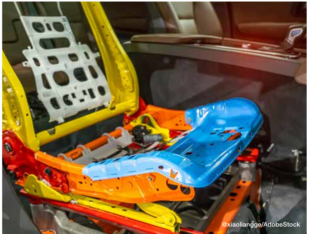
Figure 2. To achieve the stringent specifications for components like seat recliners, identical thermal processing is implemented for both EVs and ICE vehicles.

Seating Components

Generally, these components are case hardened (either carburized or carbonitrided), typically using one of the following materials:

  • 1010 and 1020 carbon steel: These are plain carbon steel with 0.10% carbon content, fairly good formability, and relatively low strength.
  • 1018 carbon steel: 1018 is a grade that’s often chosen for parts that require greater core hardness and better heat treatment response than 1010 or 1020.
  • 10B21 boron steel: Boron steels are becoming more popular in the automotive industry due to their excellent heat treatment response.
  • 4130 alloy steel and 8620 alloy steel: Alloy steels are more responsive to heat treatment than plain carbon steels, so the thermal processing specifications for parts made from these materials are often adjusted to account for the material’s innate strength properties.

Seat Belt Latches

High-strength seat belt latches are usually made from the following materials:

  • 4140 and 4130 alloy steels: 4140 alloy steel is one of the most common engineering steels used in manufacturing. For seat latches and hooks, 4140 and 4130 will be neutral hardened to increase their strength and hardness throughout due to the high performance and precision required of these parts.
  • 1050 carbon steel: 1050 is a medium carbon steel that contains 0.47–0.55% carbon content. Carbon steels are a less expensive choice when compared to alloy steels such as 4140 or 4130.

Seat Frames and Brackets

Seat frames (also known as seat brackets) give car seats their shape using slender pieces of steel joined together to form the skeleton of the seat. These components are often made from boron steels:

  • 10B21 or 15B24 boron steel: These are a good choice for seat brackets because they are only marginally more expensive than other steels used in seating but have impressive toughness, have a good heat treat response, and are weldable.

A Closer Look: Case Hardening for Seating Components

Case hardening diffuses carbon or carbon and nitrogen into the surface of a metal from the atmosphere within a furnace at high temperatures. Adding carbon or carbon and nitrogen to the surface of steel hardens a metal object’s surface while allowing the metal deeper underneath to remain softer, creating a part that is hard and wear-resistant on the surface while retaining a degree of flexibility with a softer, more ductile core. This softness and ductility create toughness in parts, allowing them to respond to stress without failing. Case hardening is a general term for this heat treating method. Depending on the materials and specifications for the part, we apply various case hardening techniques, including carburizing and carbonitriding.

Figure 3. When it comes to heat treating, innovations are rarely exclusive to EVs.

Carbonitriding

During carbonitriding, parts are heated in a sealed chamber well into the austenitic range — around 1600°F — before nitrogen and carbon are added. Because the part is heated into the austenitic range, a phase change occurs, and carbon and nitrogen atoms can diffuse into the part. Carbonitriding is used to harden surfaces of parts made of relatively inexpensive and easily machined or formed steels, which we often see in automotive metal stampings. This process increases wear resistance, surface hardness, and fatigue strength. It is also good for parts that require retention of hardness at elevated temperatures.

Neutral Hardening

Also called through hardening, neutral hardening is a very old method for hardening steel. It involves heating the metal to a specified temperature and then quenching it, usually in oil, to achieve high hardness/strength. In this process, the primary concern is increasing hardness throughout the part, as opposed to generating specific properties between the surface and the core of the part.

All of the metal components of a seat belt, including seat belt loops, tongues, and buckles, are neutral hardened. Specifications typically dictate that these components are hardened to up to 200 thousand pounds per square inch (ksi).

Because seat belt components are visible to the end consumer, their cosmetics are important in addition to their mechanical properties. It’s important to keep the furnace free of soot and thoroughly clean the parts both before and after heat treatment. Proper cleaning readies the part for secondary processing, ensuring the success of activities like polishing and chrome plating.

The Convergence of EV and ICE Vehicles

To learn more about automotive heat treating, download the free Paulo Heat Treat Guide at paulo.com/AutoGuide.

The EV revolution has significantly transformed automotive manufacturing. Despite these changes, EV parts remain remarkably similar to those of their internal combustion engine (ICE) counterparts. Consequently, any advancements in materials or heat treating processes are swiftly adopted across the entire automotive sector. When it comes to heat treating, innovations are rarely exclusive to EVs.

About the Author:

Rob Simons
Metallurgical Engineering Manager
Paulo

Rob provides internal and external customer support on process design, material behavior, job development, reduction of variation, and physical analyses at Paulo. He holds a Bachelor of Science in Metallurgical Engineering from the Missouri University of Science & Technology (formerly known as the University of Mines and Metallurgy) and has worked at Paulo since 1987. Rob has analyzed several million hardness data points and/or process behaviors, leading him to develop many process innovations in the metallurgical field.


For more information: Contact Rob at rsimons@paulo.com.


Find Heat Treating Products And Services When You Search On Heat Treat Buyers Guide.Com


Thermal Processing for EV Components Read More »

Heat Treat Radio #112: Lunch & Learn: How To Use a Hardenability Chart  

In this episode of Heat Treat Radio, Doug Glenn discusses the hardenability of materials with guest Michael Mouilleseaux, general manager at Erie Steel LTD. Michael walks us through how to interpret hardenability charts and provides detailed insights on reading these charts, including addressing the importance of understanding the nuances of complicated part geometry. 

Below, you can watch the video, listen to the podcast by clicking on the audio play button, or read an edited transcript.


The following transcript has been edited for your reading enjoyment.

Understanding a Hardenability Chart (01:59)

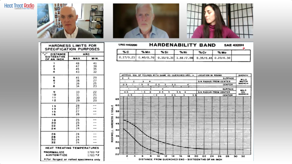
Doug Glenn: What I’d like to do is talk through this chart and learn how to read this a little bit better. And I’d like to ask questions about it because I’m not familiar with this, and I’m sure there are going to be some listeners and viewers who aren’t familiar with it. This will be just a quick tutorial on how to read these charts.

Go to the upper, right-hand corner. First off, SAE 4320H is the grade of the steel that we’re talking about?

The Heat Treat Lunch & Learn crew: Doug Glenn, Publisher of Heat Treat Today; Michael Mouilleseaux, General Manager at Erie Steel LTD.; Bethany Leone, Managing Editor of Heat Treat Today
Use this chart to follow along with the conversation.
Source of chart: Erie Steel, Ltd.

Michael Mouilleseaux: Correct.

Doug Glenn: Then the table right below that you’ve got percentage C (carbon). Is Mn manganese?

Michael Mouilleseaux: Manganese.

Doug Glenn: Thank you very much. Silicon, nickel, chrome, moly. My question is about those ranges. Is this basically saying the percentage carbon on the far left in 4320H goes anywhere from 0.17–0.23?

Michael Mouilleseaux: That is correct.

Doug Glenn: Okay. So that’s variability right there. All of those are basically telling you what the ranges are in those alloys in this grade of steel?

Michael Mouilleseaux: That is correct.

Doug Glenn: Then you go down to the top columns of this table below, and it says “Approximate diameter of rounds with same as quenched HRC in inches.” Right?

Approximate diameter of rounds with same as quenched HRC in inches
Source: Erie Steel, Ltd.

Michael Mouilleseaux: Yeah. Essentially, the first three rows are for water quenching. And the bottom three are for oil quenching.

Doug Glenn: If you go over to the second major column called “Location in round,” what’s the size of the round we’re working on here?

Michael Mouilleseaux: It can vary. Go down to where it says, “Mild Oil Quench,” then left to “Surface,” then left then go to “2 inches.” Then, go straight down to the bottom, and that’s approximately J5. So, the “Distance from Quenched End — Sixteenths of an Inch” is Jominy position 5.

Michael Mouilleseaux: If you go to Jominy position 5 on the left-hand chart, you can see the hardness limits for that; the maximum is Rockwell C 41, and the minimum is Rockwell C 29. So, the chemistry can vary provided the hardenability at J5 is 29–41.

Doug Glenn: That’s the acceptable range?

Michael Mouilleseaux: That’s the acceptable range. That’s one way of looking at it. The chemistry would allow you to do that.

Now, go back to the chart on the right-hand side and to “Surface,” move down one row to “¾ radius from center,” and go left to two inches. Moving down from there you see that is Jominy position 8. So, the surface of a two-inch round is Jominy position 5, and the ¾ radius is Jominy position 8.

If you go to the hardness chart on the left-hand side, that says that if you had a two-inch round of 4320H, and it was oil quenched, and you check the hardness at ¾ radius, then the expectation is that it would be 23–34.

Now, go back to the same chart that we were just at, and go to the “Center” row of “Mild oil quench.” Continue left to two inches, and that’s J12. Go back to the left-hand chart, and J12 is 20–29 in the center of the part.

So, the surface of the part could be 41, ¾ radius, center of the part would be 34, and the center of the part would be 29.And that would all meet the criteria.

Doug Glenn: The maximum for J5 would be 41.But at J12 you could get a 20 in the middle.

Michael Mouilleseaux: Right. That is one way to look at this chart. But there is another way.

Notice that it says “rounds.”There are some nuances to having flats and rectangles because, if you think about it, for the cross-sectional area of a rectangle, the hardenability is going to be determined by the direction that it is thinnest, not by the direction that it is thickest.

Take a gear tooth, for example: in the chart that we just made up the gear teeth, the root of the gear was about a half inch, just slightly more; and if we go to this same chart, go to “Center” of “Mild oil quench,” and then go to a “0.5 inch,” and when you go straight down, that’s the J3.

Is a gear necessarily a round? Of course, the answer to that is no. So, in complex shapes you can use this data, but you have to interpolate it in order to understand it.

To some extent, the first time you run this, you’re going to say, “I have a gear, and the root is a half inch across. And I know that the J3 is 40. And I’ll run this part, and I’ll section it and I’ll measure it and it’s 40. And I’ll say that’s a good approximation of that.” And experientially, you build confidence in this, that is, it’s your operation, your quenching operation, and your components. It allows you to interpolate these, and they become extremely useful.

So, is it definitive? No. Is it useful? Yes.

Doug Glenn: It gives you a ballpark, right? I mean, it’s giving you something, maybe guardrails.

Michael Mouilleseaux: It gives you a ballpark; it gives you guardrails. And I can tell you that after having run gear product in the same equipment for ten years, I can say that it’s definitive. I can say that if I have this hardenability, and I get this hardenability number for this heat, and these gears are made from this heat of steel, and it has a J3 of 42. If I’m at 38, I know something is going on other than just hardenability. And, at that point, I would suspect my heat treat operation.

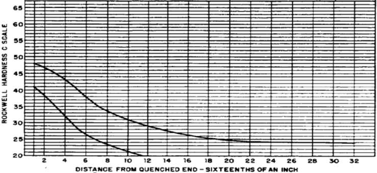
Doug Glenn: Yeah. I have one more question about this chart: On the bottom right part of the graph there are two plot lines on there. What do those represent? I was thinking one represented the water quench and the bottom one represents the oil quench.

Plot lines representing maximum hardenability and minimum hardenability
Source: Erie Steel, Ltd.

Michael Mouilleseaux: The top one represents the maximum hardenability. And the lower the lower one represents the minimum hardenability.

Doug Glenn: That’s your band. Okay. Those are basically your values over on the left-hand side then. Very good.

I don’t know about you, but I found that helpful. I really didn’t ever know how to read these tables. So, maybe someone else will find that useful. Thanks, Michael. I appreciate your expertise.

Michael Mouilleseaux: It’s been my pleasure.

About The Guest

Michael Mouilleseaux
General Manager at Erie Steel, Ltd.
Sourced from the author

Michael Mouilleseaux is general manager at Erie Steel LTD. Mike has been at Erie Steel in Toledo, OH, since 2006 with previous metallurgical experience at New Process Gear in Syracuse, NY, and as the Director of Technology in Marketing at FPM Heat Treating LLC in Elk Grove, IL. Having graduated from the University of Michigan with a degree in Metallurgical Engineering, Mike has proved his expertise in the field of heat treat, co-presenting at the 2019 Heat Treat show and currently serving on the Board of Trustees at the Metal Treating Institute.

Contact Mike at mmouilleseaux@erie.com.


Search Heat Treat Equipment And Service Providers On Heat Treat Buyers Guide.Com


Heat Treat Radio #112: Lunch & Learn: How To Use a Hardenability Chart   Read More »

Advantages of Laser Heat Treatment, Part 2: Energy Efficiency, Sustainability, and Precision

A discussion of laser heat treating begun in Heat Treat Today’s Air & Atmosphere 2024 print edition would not be complete without highlighting key sustainability advantages of this new technology. In this Technical Tuesday installment, guest columnist Aravind Jonnalagada (AJ), CTO and co-founder of Synergy Additive Manufacturing LLC, explores how sustainability and energy-efficiency are driven by precision heat application and minimal to zero distortion. The first part, “Advantages of Laser Heat Treatment: Precision, Consistency, and Cost Savings”, appeared on April 2, 2024, in Heat Treat Today, as well as in Heat Treat Today’s January/February 2024 Air & Atmosphere print edition.

This informative piece was first released in Heat Treat Today’s May 2024 Sustainability Heat Treat print edition.


Laser heat treating is a transformative process that promises superior performance and sustainable practices. Laser heat treating epitomizes precision in surface heat treatment techniques, targeting localized heating of steel or cast-iron components. Laser radiation raises the surface temperature of the metal in the range of 1652°F to 2552°F (900°C to 1400°C), inducing a transformation from ferritic to austenitic structure on the metal surface. As the laser beam traverses the material, the bulk of the component self-quenches the heated zone. During this process, carbon particles are deposited in the high temperature lattice structure and cannot diffuse outward because of quick cool down resulting in the formation of hard martensite to a case depth up to 0.080” (2 mm), crucial for enhancing material properties.

Sustainability through Energy Efficiency

Contact us with your Reader Feedback!

When considering the energy consumption of a typical laser heat treating operation, it’s essential to acknowledge the continuous advancements in laser technology. Modern laser heat treating systems integrate high-power lasers, water chillers, and motion systems, such as robots or CNC machines. With a typical wall plug efficiency of around 50% for diode lasers, these systems represent a significant improvement in energy utilization compared to conventional methods. The typical energy consumption cost for running a 6 kW laser heat treating system is $20-$30/day. The calculation is based on an 8-hour shift with a duty cycle of 80% calculated at national average electric cost of 15.45 cents/kilowatt-hour.

Self-Quenching Mechanism

Laser heat treating operates on the essential principle of self-quenching, leveraging the bulk mass of the material for rapid cooling. This eliminates the dependence on quenchants required in flame and induction heat treating processes, further reducing environmental impact and operational costs.

Precision and Minimal Distortion

At the heart of laser heat treating lies its sustainable and energy-efficient attributes, driven by two fundamental features: precision heat application and minimal to zero distortion of components post-heat treatment. When compared to the conventional methods such as flame and induction hardening, laser heat treatment offers significantly localized heating. This precision allows for targeted heat treatment within millimeter precision right where the hardness is needed, optimizing energy utilization and operational efficiency. Furthermore, the high-power density of lasers enables hardening with minimal to zero distortion, eliminating or reducing the need for subsequent machining operations like hard milling or grinding.

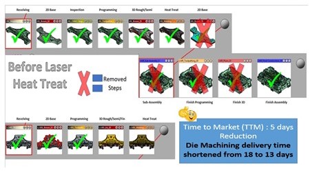
Case Study image; 16 small boxes of auto parts undergoing die machining, laser heat treat; blue inset box
Comparison of the die construction process before and after laser hardening
Source: Autodie LLC

A Case Study of Laser Heat Treating in Automotive Stamping Dies

The image above identifies process steps typically involved in construction of automotive stamping dies. During the process of manufacturing automotive stamping dies, the cast dies are first soft milled, intentionally leaving between 0.015” and 0.020” of extra stock material on the milled surfaces. This is done to account for any distortions that will result from the subsequent conventional heat treatment processes such as flame or induction. After heat treating, the dies are then hard milled back to tolerance and assembled.

In the laser heat treating process, by contrast, dies are finish machined to final tolerance in the first step and then laser heat treated without distortion. No secondary hard milling operation is necessary. Typical cost savings for our automotive tool and die customer exceeds over 20% due to elimination of hard milling operation. Total energy reduction is significant, although not computed here. This may result in savings if carbon credits become monetized.

Laser heat treating’s precision, efficiency, and minimal environmental footprint position it as an environmentally friendly option for heat treat operations. As industries continue to prioritize sustainability, laser heat treating may set new standards for excellence and environmental stewardship.

About the Author:

Aravind Jonnalagadda
CTO and Co-Founder
Synergy Additive Manufacturing LLC
Source: LinkedIn

Aravind Jonnalagadda (AJ) is the CTO and co-founder of Synergy Additive Manufacturing LLC. With over 15 years of experience, AJ and Synergy Additive Manufacturing LLC provide high-level laser systems and laser heat treating, specializing in high power laser-based solutions for complex manufacturing challenges related to wear, corrosion, and tool life. Synergy provides laser systems and job shop services for laser heat treating, metal based additive manufacturing, and laser welding.

For more information: Contact AJ at aravind@synergyadditive.com or synergyadditive.com/laser-heat-treating.


Find Heat Treating Products and Services When You Search on Heat Treat Buyers Guide.com


Advantages of Laser Heat Treatment, Part 2: Energy Efficiency, Sustainability, and Precision Read More »

How To Reduce Carbon Footprint During Heat Treatment

Given changing ecological and economic conditions, carbon neutrality is becoming more important, and the heat treatment shop is no exception. In the context of this article, the focus will be on how manufacturers — especially those with in-house heat treat — can save energy by evaluating heating systems, waste heat recovery, and the process gas aspects of the technology.

This article, written by Dr. Klaus Buchner, head of Research and Development at AICHELIN HOLDING GmbH, was released in Heat Treat Today April/May 2024 Sustainable Heat Treat Technologies print edition.


Introduction

Contact us with your Reader Feedback!

Uncertainties in energy supply and rising energy costs remind us of our dependence on fossil fuels. This underlines the need for a sustainable energy and climate policy, which is the central challenge of our time.

European policymakers have already taken the first steps towards a green energy revolution, and the heat treatment industry must also take responsibility. Many complementary measures, however, are needed that can be applied to new and existing thermal and thermochemical heat treatment lines.

Heat Treatment Processes and Plant Concepts

The heat treatment process itself is based on the requirements of the component parts, and especially on the steel grade used. If different concepts are technically comparable, it is primarily the economic aspect that is decisive, and not the carbon footprint — at least until now. Advances in materials technology and rising energy costs are calling for production processes to be modified.

Figure 1. Donut-shaped rotary-hearth furnace for carburizing with press quenching
Source: AICHELIN HOLDING GmbH

An example is the quenching and tempering of automotive forgings directly from the forging temperature without reheating, which has shown significant potential for energy and CO2 savings. Although the reduced toughness or measured impact energy of quenching and tempering from the forging temperature may be a drawback due to the coarser austenite grain size, this can be partially improved by Nb micro-alloyed steels and higher molybdenum (Mo) contents for more temper-resistant steels; it may also be necessary to use steels with modified alloying concepts when changing the process.1, 2 AFP steels (precipitation-hardening ferritic pearlitic steels) and bainitic air-hardening steels can also be interesting alternatives, since reheating (an energy-intensive intermediate step) is no longer necessary.

Similar considerations apply to direct hardening instead of single hardening in combination with carburizing processes because of the elimination of re-austenitizing. Distortion-sensitive parts often need to be quenched in fixtures due to the dimensional and shape changes caused by heat treatment. Heat treated parts are often carburized in multipurpose chamber furnaces or small continuous furnaces, cooled under inert gas, reheated in a rotary-hearth furnace, and quenched in a hardening press. In contrast, ring-shaped (aka donut-shaped) rotary-hearth furnaces allow carburizing and subsequent direct quenching in the quench press in a single treatment step. Figure 1 shows a typical ring-shaped rotary-hearth furnace concept for heat treating 500,000 gears per year/core hardness depth (CHD) group 1 mm.

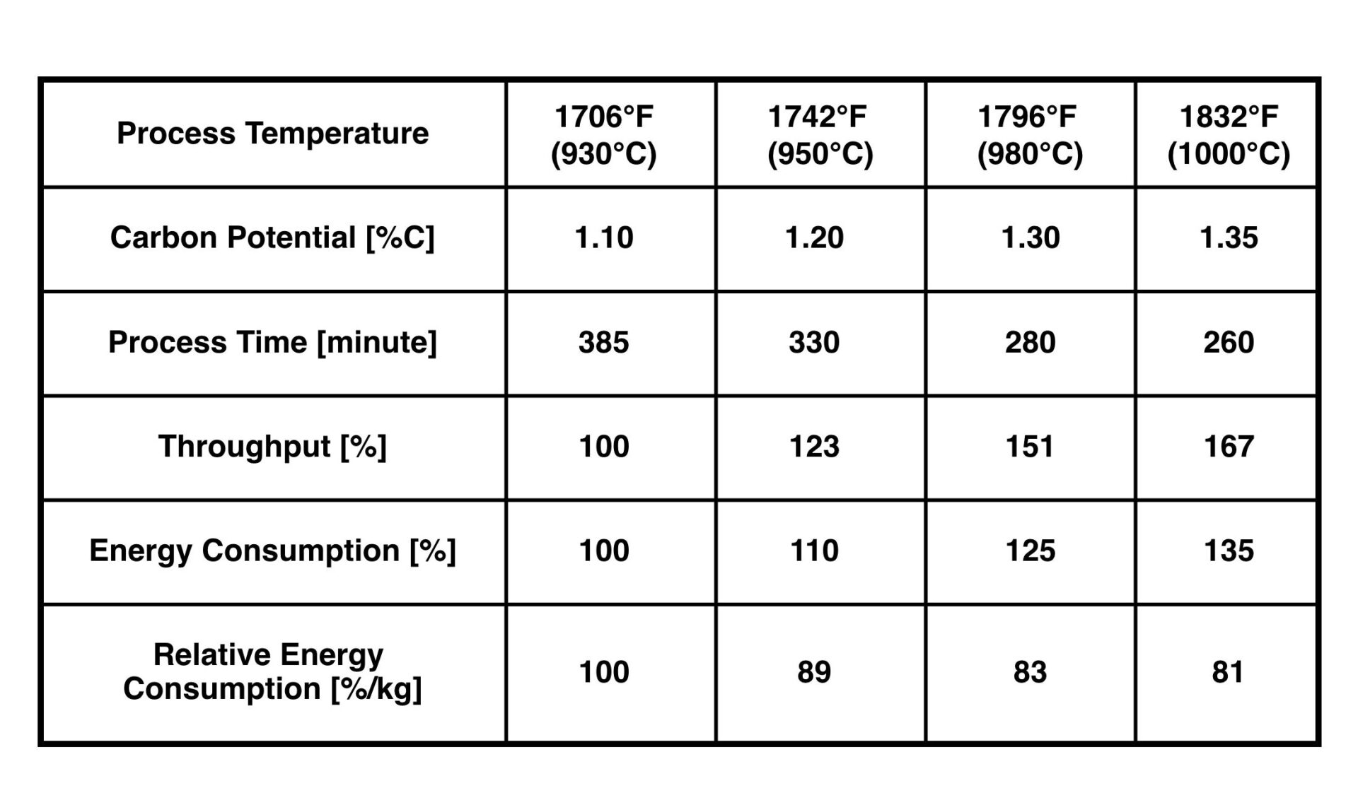
Table 1. Saving potential due to increased process temperature for gas carburizing (pusher type furnace, 20MnCr5, CHD-group 1 mm)
Source: AICHELIN HOLDING GmbH

This ring-shaped rotary-hearth concept can save up to 25% of CO2 emissions, compared to an integral quench furnace line (consisting of four single-chamber furnaces, one rotary hearth furnace with quench press and two tempering furnaces as well as two Endothermic gas generators). Due to the reduced total process time (without reheating) and the optimized manpower, the total heat treatment costs can be reduced by 20–25%.

The high-temperature carburizing aspect should also be mentioned, although the term “high-temperature carburizing” is not fully accepted nor defined by international standards. As the temperature increases, the diffusion rate increases and the process time decreases. As shown in Table 1, the additional energy consumption is less than the increase in throughput that can be achieved. Therefore, the relative energy consumption per kg of material to be heat treated decreases as the process temperature increases.

There are three key issues to consider when running a high-temperature carburizing process:

  • Steel grade: Fine-grain stabilized steels are required for direct hardening at temperatures of 1832°F (1000°C). Microalloying of Nb, Ti, and N as well as a favorable microstructure of the steels reduce the growth of austenite grains and allow carburizing temperatures up to 1922°F (1050°C) for several hours.
  • Furnace design: In addition to the general aspects of the optimized furnace technology (e.g. heating capacity, insulation materials, and feedthroughs), failure-critical components must be considered separately in terms of wear and tear, whereby condition monitoring tools can support maintenance in this area.
  • Distortion: This is always a concern, especially in the case of upright loading of thin-walled gear sections. As such, numerical simulations and/or experimental testing should be performed at the beginning to estimate possible changes in distortion and to take measures if necessary.
Figure 2. Recuperative burner with SCR system for NOx reduction Source: AICHELIN HOLDING GmbH

Heating System

Based on an energy balance that considers total energy losses, and preferably also temperature levels, it can be seen that the heating system plays a significant role. In addition to the obvious flue gas loss in the case of a gas-fired thermal processing furnace, the actual carbon footprint must be critically examined.

In the case of natural gas, the upstream process chain is often neglected in terms of CO2 emissions, but the differences in gas processing (which are directly linked to the reservoirs) and in gas transportation can be a significant factor.3 However, the analysis of energy resources in the case of electric heating systems is much more important. This results in specific CO2 emissions between 30–60 gCO2/kWh (renewable-based electricity mix) and 500–700 gCO2/kWh (coal-based electricity mix). Therefore, a general comparison between natural gas heating and electric heating systems in terms of carbon footprint is often misleading.

Figure 3. Comparison of specific CO2 emissions Source: AICHELIN HOLDING GmbH

Nevertheless, in the case of gas heating, the aspect of combustion air preheating should be emphasized, as it has a significant influence on combustion efficiency. The technical possibilities in this area are well known and include both systems with central air preheating and decentralized concepts, where the individual burner and the heat exchanger form a single unit. Recuperator burners are often used in combination with radiant heating tubes (indirect heating) in the field of thermochemical heat treatment. With respect to oxy-fuel burners, it should also be noted that the formation of thermal NOx increases with increasing combustion temperature and temperature peaks. To avoid exceeding NOx emissions, staged combustion and so-called “flameless combustion” — characterized by special internal recirculation — and selective catalytic reduction (SCR) can be used. The latter secondary measure, together with selective non-catalytic reduction (SNCR), has been state-of-the-art in power plant design for decades and has become widely known because of its use in the automotive sector. This system can also be adapted to single burners (Figure 2). In this way, NOx emissions can be reduced to 30 mg/Nm3 (5% reference oxygen), depending on the injection of aqueous urea solution, as long as the exhaust gas temperature is in the range of 392/482°F (200/250°C) to 752/842°F (400/450°C).4

Whether electric heating is a viable alternative depends on both the local electricity mix and the design of the heat treatment plant, which may limit the space available for the required heating capacity. In addition to these technical aspects, the security of supply and the energy cost trends must also be considered. Both of these factors are significantly influenced by the political environment. Figure 3 shows an example of the specific carbon footprint per kg of heat treated material with the significant losses based on the example of an integral quench furnace concept in the double-chamber and single-chamber variants electrically heated (E) and gas heated (G). The electric heating is based on a fossil fuel mix of 485 gCO2/kWh. Once again, it is clear that a general statement regarding CO2 emissions is not possible; rather, the boundary conditions must be critically examined.

Waste Heat Recovery — Strengths and Weaknesses of the System

Although improvements in the energy efficiency of heat treatment processes, equipment designs, and components are the basis for rational energy use, from an environmental perspective it is important to consider the total carbon footprint. An energy flow analysis of the heat treatment plant, including all auxiliary equipment, shows the total energy consumption and thus the potential savings. Quite often the temperature levels and time dependencies involved preclude direct heat recovery within the furnace system at an economically justifiable investment cost. In this case, cross-plant solutions should be sought, which require interdepartmental action but offer bigger potential.

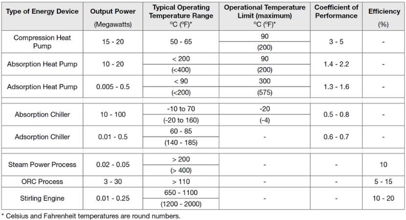
In addition to the classic methods of direct waste heat utilization using heat exchangers, also in combination with heat accumulators, indirect heat utilization can lower or raise the temperature level of the waste heat by using additional energy (chiller or heat pump) or convert the waste heat into electricity. The overview in Table 2 provides reference values in terms of performance class and temperature level for the alternative technologies listed.

Process Gas for Case Hardening

Case hardening — a thermochemical process consisting of carburizing and subsequent hardening — gives workpieces different microstructures across the cross-section, the key factor being high hardness/strength in the edge region. A distinction can be made between low pressure carburizing in vacuum systems and atmospheric carburizing at normal pressure. Both processes have different advantages and disadvantages, with atmospheric heat treatment being the dominant process.

Table 2. Overview of alternative waste heat applications5, 6
Source: AICHELIN HOLDING GmbH

In terms of carbon footprint, atmospheric heat treatment has a weakness due to process gas consumption. To counteract this, the following aspects have to be considered: thermal utilization of the process gas — indirectly by means of heat exchangers or directly by lean gas combustion (downcycling); reprocessing of the process gas (recycling); reduction of the process gas consumption by optimized process control; and use of CO2-neutral media (avoidance). This article focuses on avoidance by optimizing process gas consumption and using of CO2-neutral media.

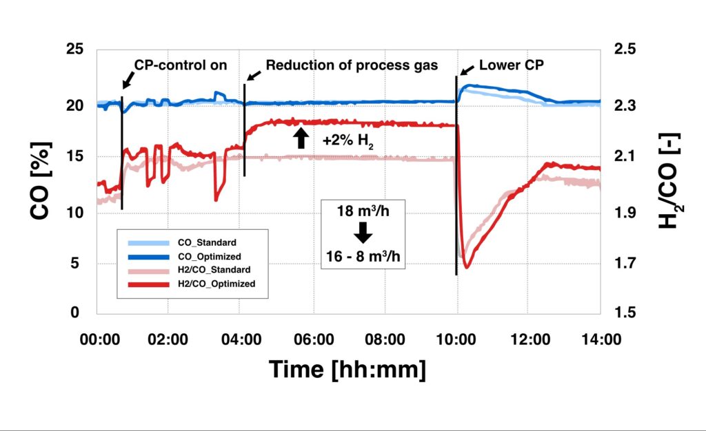
Typically, heat treatment operations are still run with constant process gas quantities based on the most unfavorable conditions. Based on the studies of Wyss, however, process control systems offer the possibility to adapt the actual process gas savings to the actual demand.7 In a study of an industrial chamber furnace, a 40% process gas savings was demonstrated for a selected carburizing process. In this heat treatment process with a case hardness depth of 2 mm, the previously used constant gas flow rate of 18 m3/h was reduced to 16 m3/h for the first process phase and further reduced to 8 m3/h after 3 hours. Figure 4 shows the analysis of the gas atmosphere, where an increase in the H2 concentration could be detected due to the reduction of the gas quantities. With respect to the heat treatment result, no significant difference in the carburizing result was observed despite this significant reduction in process gas volume (and the associated reduction in CO2 emissions). The differences in the carbon profiles are within the expected measurement uncertainty.

Figure 4. CO and H2/CO concentration at various process gas volumes Source: AICHELIN HOLDING GmbH

The carbon footprint of the process gas, however, must be fundamentally questioned. In the field of atmospheric gas carburizing, process gases based on Endothermic gas (which is produced by the catalytic reaction of natural gas or propane with air at 1832–1922°F/1000–1050°C) and nitrogen/methanol and methanol only systems have established themselves on a large scale. Methanol production is still mostly based on fossil fuels (natural gas or coal), the latter being used mainly in China. Although alternative CO2-neutral processes for partial substitution of natural gas — keywords being “power to gas” (P2G) or “synthetic natural gas” (SNG) — have already been successfully demonstrated in pilot plants, there are no signs of industrial penetration. Nevertheless, there is a definite industrial scale in the area of bio-methanol synthesis, though so far, purely economic considerations speak against it, as CO2 emissions are still not taken into account.

The question of the use of bio-methanol in atmospheric gas carburizing has been investigated in tests on an integral quench furnace system. A standard load of component parts with a CHD of 0.4 mm was used as a reference. Subsequently, the heat treatment process was repeated with identical process parameters using bio-methanol instead of the usual methanol based on fossil fuels. Both the laboratory analyses of the methanol samples and the measurements of the process gas atmosphere during the heat treatment process, as well as the evaluation of the sample parts with regard to the carbon profile during the carburizing process, showed no significant difference between the different types of methanol. Although this does not represent long-term experience, these results underscore the fundamental possibility of media substitution and the use of CO2-neutral methanol.

Conclusion

Facing the challenges of global warming — intensified by the economic pressure of rising energy costs — this article demonstrates the energy-saving potential in the field of heat treatment. In addition to already established solutions, the possibilities of the smart factory concept must also be integrated in this industrial sector. Thus, heat treatment comes a significant step closer to the goal of a CO2-neutral process in terms of Scopes 1, 2, and 3 regarding emissions under the given boundary conditions.

References

[1] Karl-Wilhelm Wegner, “Werkstoffentwicklung für Schmiedeteile im Automobilbau,” ATZ Automobiltechnische Zeitschrift 100, (1998): 918–927, https://doi.org/10.1007/BF03223434.
[2] Wolfgang Bleck and Elvira Moeller, Steel Handbook (Carl Hanser Verlag GmbH & Co. KG, 2018).
[3] Wolfgang Köppel, Charlotte Degünther, and Jakob Wachsmuth, “Assessment of upstream emissions from natural gas production in Germany,” Federal Environment Agency (January 2018): https://www.umweltbundesamt.de/publikationen/bewertung-der-vorkettenemissionen-beider.
[4] Klaus Buchner and Johanes Uhlig, “Discussion on Energy Saving and Emission Reduction Technology of Heat Treatment Equipment,” Berg Huettenmaenn Monatsh 168 (2021): 109–113, https://doi.org/10.1007/s00501-023-01328-5.
[5] Technologie der Abwärmenutzung. Sächsische Energieagentur – SAENA GmbH, 2. Auflage, 2016.
[6] Brandstätter, R.: Industrielle Abwärmenutzung. Amt der OÖ Landesregierung, 1. Auflage, 109–113, https://doi.org/10.1007/s00501 02301328-5.
[7] U. Wyss, “Verbrauch an Trägergas bei der Gasaufkohlung,” HTM Journal of Heat Treatment Materials 38, no. 1 (1983): 4-9, https://doi.org/10.1515/htm-1983-380102.

About the Author

Dr. Klaus Buchner Head of Research and Development AICHELIN HOLDING GmbH

Klaus Buchner holds a doctorate and is the head of research and development at AICHELIN HOLDING GmbH. This article is based on Klaus Buchner’s article, “Reduktion des CO2-Fußabdrucks in der Wärmebehandlung” in Prozesswärme 01-2023 (pp. 42-45).

For more information: Klaus at klaus.buchner@aichelin.com.

This article content is used with the permission of heat processing, which published this article in 2023.

Find Heat Treating Products And Services When You Search On Heat Treat Buyers Guide.Com

How To Reduce Carbon Footprint During Heat Treatment Read More »

Advantages of Laser Heat Treatment: Precision, Consistency, and Cost Savings

Laser heat treating, a form of case hardening, offers substantial advantages when distortion is a critical concern in manufacturing operations. Traditional heat treating processes often lead to metal distortion, necessitating additional post-finishing operations like hard milling or grinding to meet dimensional tolerances.

This Technical Tuesday article was originally published in first published in Heat Treat Today’s January/February 2024 Air & Atmosphere print edition.


In laser heat treating, a laser (typically with a spot size ranging from 0.5″ x 0.5″ to 2″ x 2″) is employed to illuminate the metal part’s surface. This results in a precise and rapid delivery of high-energy heat, elevating the metal’s surface to the desired transition temperature swiftly. The metal’s thermal mass facilitates rapid quenching of the heated region resulting in high hardness.

Key Benefits of Laser Heat Treating

Consistent Hardness Depth

Laser heat treatment achieves consistent hardness and hardness depth by precisely delivering high energy to the metal. Multiparameter, millisecond-speed feedback control of temperature ensures exacting specifications are met.

Minimal to Zero Distortion

Due to high-energy density, laser heat treatment inherently minimizes distortion. This feature is particularly advantageous for a variety of components ranging from large automotive dies to gears, bearings, and shafts resulting in minimal to zero distortion.

Precise Application of Beam Energy

Unlike conventional processes, the laser spot delivers heat precisely to the intended area, minimizing or eliminating heating of adjoining areas. This is specifically beneficial in surface wear applications, allowing the material to be hardened on the surface while leaving the rest in a medium-hard or soft state, giving the component both hardness and ductility.

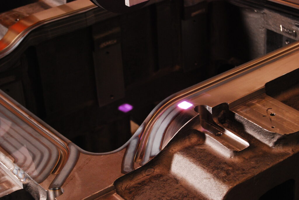
Figure 1. Laser heat treating of automotive stamping die constructed from D6510 cast iron material (Source: Synergy Additive Manufacturing LLC)

No Hard Milling or Grinding Required

The low-to-zero-dimensional distortion of laser heat treatment reduces or eliminates the need for hard milling or grinding operations. Post heat treatment material removal is limited to small amounts removable by polishing. Eliminating hard milling or grinding operations saves substantial costs in the overall manufacturing process of the component. Our typical tool and die customers have seen over 20% cost savings by switching over to laser heat treating.

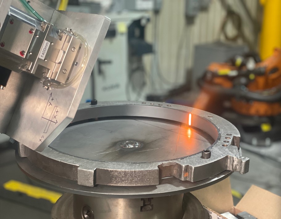
Figure 2. Laser heat treating of machine tool
components (Source: Synergy Additive Manufacturing LLC)

Applicable for a Large Variety of Materials

Any metal with 0.2% or more carbon content is laser heat treatable. Hardness on laser heat treated materials typically reaches the theoretical maximum limit of the material. Many commonly used steels and cast irons in automotive industry such as A2, S7, D2, H13, 4140, P20, D6510, G2500, etc. are routinely laser heat treated. A more exhaustive list of materials is available at synergyadditive.com/laser-heat-treating.

Conclusions

Aravind Jonnalagadda CTO and Co-Founder Synergy Additive Manufacturing LLC Source: LinkedIn

Laser heat treatment is poised to witness increased adoption in the automotive and other metal part manufacturing sectors. The adoption of this process faces no significant barriers, aside from the typical challenges encountered by emerging technologies, such as lack of familiarity, limited hard data, and a shortage of existing suppliers. The substantial savings, measured in terms of cost, schedule, quality, and energy reduction, provide robust support for the continued embrace of laser heat treatment in manufacturing processes.

For more information: Contact AJ at aravind@synergyadditive.com or synergyadditive.com/laser-heat-treating.

Find Heat Treating Products And Services When You Search On Heat Treat Buyers Guide.com 

Advantages of Laser Heat Treatment: Precision, Consistency, and Cost Savings Read More »

Heat Treat Radio #107: Stop-Off Coatings 101, with Mark Ratliff

Needing to learn more about the fundamentals and latest developments of stop off coatings? Mark Ratliff, president of AVION Manufacturing Company, Inc., applies his background in chemical engineering to understand and create what makes the best stop-off coatings/paints for carburizing and other heat treat processes. In this episode, Mark and Heat Treat Radio host, Doug Glenn, uncover the varieties of coatings, their uses, and the future of coating solutions.

Below, you can watch the video, listen to the podcast by clicking on the audio play button, or read an edited transcript.


The following transcript has been edited for your reading enjoyment.

Chemistry in Coatings: Mark Ratliff’s Start in the Industry (00:22)

Contact us with your Reader Feedback!

Doug Glenn: I have the really great honor today of talking with Mark Ratliff from AVION Manufacturing. We’re going to do a “painting class” . . . kind of, but not really. Industrial paint — we’re going to talk about stop-off paints and things of that sort.

Mark has been working at AVION, currently located in Medina, Ohio, since 1994. He graduated with a Bachelor of Science degree in chemical engineering from the University of Cincinnati. Prior to that — I did not know this about you, Mark — he worked at Shore Metal Treating with your father, huh?

Mark Ratliff: That’s correct, yes.

Doug Glenn: How long was he there?

Mark Ratliff: Well, he started the company. I went working there and was loading baskets of parts since I was about 8 years old. He would pay me $5.00 for a basket, “under the table,” and that was a lot of money back then. I was really rich, at the time!

Mark Ratliff, President, Avion Manufacturing (Source: AVION Manufacturing)

Doug Glenn: That’s pretty cool. It is very interesting to see people’s backgrounds and how they got involved in the industry. A lot of people start young, you know? You may win the record though — 8 years old! The labor board may be calling about your childhood.

Why Use Stop-Off Paints? (01:54)

Let’s talk today. Technically, we want to talk about something that not everybody may know about, and I think you and your company are kind of experts on these things, and that’s stop-off paints. Just from a 30,000-foot view — and you don’t have to go into a lot of detail here, Mark — what are stop-off paints and why do we use them?

Mark Ratliff: Stop-off paints are protective barrier-type coatings. What they do is prevent either carburization or the nitriding process from entering into the steel. They were created probably well over 50 years ago as a replacement for copperplating these parts. In the past, a long time ago, they would copperplate the part that they did not want carburized or nitrided. That’s a time-consuming process as well as being very expensive. The stop-off coatings were developed as an economical alternative to copperplating.

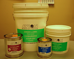
AVION Line of Stop-Offs (Source: AVION Manufacturing)

Doug Glenn: When you say “copperplating,” does that mean it was actual thin sheets of copper metal?

Mark Ratliff: That’s correct, yes.

Doug Glenn: And you actually had to wrap whatever you did not want nitrided or carburized in this copper and that would keep it from nitriding?

Mark Ratliff: That’s correct, yes.

Doug Glenn: Just in case people don’t know — but I would imagine that most people that are listening to this do know — nitriding and carburizing are both surface hardening technologies in which either nitrogen (in the case of nitriding) or carbon (in the case of carburizing) are infused into the surface. That, of course, gives improved wear properties, typically corrosion properties to those areas that receive the infusion of the metal.

Why do people not want the nitrogen or carbon to be infused to certain areas of the part?

Mark Ratliff: When you harden a part, as with carburization or nitriding, a lot of times hardness equates to brittleness. So you may induce certain stress in various parts, in various areas.

Also, if you want to do a post-heat treatment machining on the part, it would be virtually impossible if that part were carburized or nitrided because the surface is so hard that the tool can’t cut through it to do further machining on the part.

“If you want to do a post-heat treatment machining on the part, it would
be virtually impossible if that part were carburized or nitrided because the surface is so hard that the tool can’t cut through it to do further machining on the part.”

— Mark Ratliff, AVION Manufacturing

Doug Glenn: Gotcha.

Can you give a couple examples of parts, and if you can do a description of where on those parts you might apply a stop-off coating?

Mark Ratliff: Well, a lot of times the end user (the customer) is painting an end of a shaft where he’ll heat treat the shaft and make the shaft harder, but he wants to spin a thread on the end of that shaft. That’s a prime example of why you would use a stop-off coating.

A lot of times, the parts are made with the threads already on, but you don’t want those threads to be hardened because, again, hardness equals brittleness, and those threads would crack off after heat treatment. That would be an area where you would apply a stop-off coating.

Physical Properties of Stop-Offs (05:27)

Doug Glenn: Tell us a little bit about the actual physical “properties" of these stop-off coatings. We also call them “stop-off paints.” I’m assuming a lot of times these are just painted on — it’s a liquid format.

Mark Ratliff: They are all supplied in liquid form with the viscosity ranging right around 3500–8500 centipoise (cP). For the carburizing stop-off, we have two different kinds. (This is not new in the industry; most people know the formulations of the stop-offs.)

We have boric acid-based stop-offs; we have two different kinds of that — a waterborne and a solvent borne. The idea behind the boric acid-based stop-offs is that as the boric acid thermally decomposes, it creates a boron oxide glass. This glass is actually the diffusion barrier of the carbon. What’s nice about the boric acid-based stop-offs is that they’re water washable after the heat treatment process; the coating and the residue can get washed off.

Another type of stop-off coating that we have is based on silicate chemistry. A silicate chemistry is basically like putting a glass on the part. It’s more of a ceramic-based coating. It works very, very well, but the drawback of the silicate-based stop-offs is that you have to bead-blast the parts after heat treatment; it does not wash off in water.

Doug Glenn and Mark Ratliff

Doug Glenn: So, you’ve got to brush it off.

Mark Ratliff: You’ve got to brush it off, mechanically, correct.

Doug Glenn: That’s interesting.

When I think of painting something on and then putting it into a furnace, the first thing I think of is that paint is going to get completely obliterated in the furnace. But you just kind of answered that question. Those things will either transform into a glass or a ceramic of some sort after they’ve been in high heat for a while, and that’s what creates the barrier.

Mark Ratliff: That’s correct.

You have the active ingredient in the stop-offs  — you either have the silicate or you have the boric acid. Those are the active ingredients. The vehicle that the paint itself  — be it the water-based latex or the solvent-borne bead — those do, indeed, get charred off. They get burned off, leaving the active ingredient behind.

Doug Glenn: Are you able to use either of those — the water-based or the solvent-based — in vacuum furnaces? Do you have any trouble with off-gassing and things of that sort?

Mark Ratliff: Yes, a little bit. We’ve got to be careful in the vacuum furnace market because you do have the off-gassing. The combination of the vacuum and the heat at once can cause the coating to boil and blister. We do recommend pre-heat treatments when doing a vacuum operation.

Doug Glenn: And the pre-heat just kind of helps it adhere to the part without the blistering, I guess?

Mark Ratliff: That’s correct. And it drives off a lot of the residual water or solvent that might be left in the coating.

Different Chemistry, Different Technology: Plasma Nitriding Stop-Off Coatings (08:32)

Doug Glenn: Okay, good.

Now I understand that there is a new product coming out on the nitriding end of things. Can you tell us a little bit about that and why you’re developing it?

Mark Ratliff: We’ve been making a nitriding stop-off coating since 1989 when we came out with our water-based version. We actually had it patented. We were the first on the market with a water-based nitriding stop-off. This particular stop-off has been used in the industry for 45 years now.

We got called by a current customer asking, “Hey, do you have a plasma or an ion-nitriding stop-off?” At the time, we did not. So, we developed a new plasma — aka, ion-nitriding — stop-off, and that’s a different chemistry, different technology. It is going to be available in the market very soon.

Doug Glenn: Interesting.

I’m curious about this: Are stop-off paints used more in carburizing or nitriding?

Mark Ratliff: By far, carburizing — it’s probably 10 to 1 carburizing to nitriding, for sure.

Doug Glenn: Okay, gotcha.

This episode of Heat Treat Radio is sponsored by AVION.

So, you’ve been doing this for 30 or some years, right?

Mark Ratliff: It will be my 30th anniversary in the month of April.

Doug Glenn: Very nice! Well, congratulations.

Mark Ratliff: I did work for my father prior to that, when he ran AVION for many years before that.

Doug Glenn: Well, congratulations, first off — that’s good. It shows longevity, which is good.

Memorable Moment of Innovation (11:11)

Doug Glenn: Has there been a memorable challenge that you had to deal with, with these stop-off paints?

Mark Ratliff: One thing I’m particularly proud of, Doug, is we always had the water-based carburizing stop-off coating — both varieties — the boric acid-based and the silicate-based. I had a few customers reach out to me and say, “Hey, we’re doing heat treatment for the aerospace industry or for the automotive industry, and they don’t like water-based coatings on their parts,” because you run into corrosion, you run into rust, and so forth and so on. So, these customers asked me to create the solvent-borne, which we did about seven or eight years ago.

One thing I’m particularly proud of is, I got called by the Fiat Chrysler plant in Michigan (they’re going by Stellantis, now), and unbeknownst to them, their current stop-off provider, at the time, changed the formulation. (That was due to the REACH regulations in Europe.) Since they changed the formulation, Stellantis started seeing all these problems. So, they reached out to me and asked, “Do you have an equivalent? We’d like a solvent-borne stop-off.” I was quick to respond, “Oh, by the way, yes, we do. And yes, our product is better,” because even though it’s solvent-borne, we created a nonflammable stop-off coating. In addition to being nonflammable, the solvent that we used in the coating is VOC exempt — VOC meaning volatile organic compounds — which are basically air pollutants that people want to avoid when using these stop-off coatings.

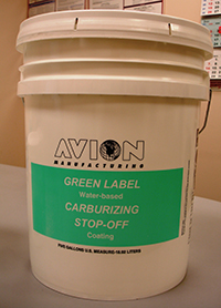
AVION Green Label pail (Source: AVION Manufacturing)

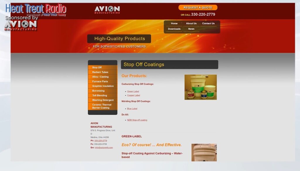
Doug Glenn: Okay, very interesting. I was going to ask you — because I saw on your website — about your green label, which you kind of hit on with the VOC part, but can you tell us a little bit about the green label products that you have and why you’re calling them “green label”?

Mark Ratliff: We called it “green label” a long time ago — that was our original stop-off which kicked off our business 50+ years ago. But I think you’re referring to our eco green label which we created about two years ago.

We’ve been getting a lot of pressure to remove VOCs from our coatings. Clients like John Deere and Caterpillar said, “Hey, we love your coating, but if you could do anything to get the VOCs out of it, we’d really appreciate it.” So, that was one of the biggest goals and one of the biggest accomplishments — to create a coating that didn’t have any of these VOC or HAP (hazardous air pollutants)-type solvents in the coating, and we have successfully done that.

Doug Glenn: That’s good. Especially in the ‘green movement’ that’s going on today, that’s obviously very important.

What coating solution should heat treaters be looking at, in the near future? Is it just VOC stuff, the lack of VOC, or what?

Mark Ratliff: Well, yes, of course. I mean, we’re proud to say that all of our coatings are virtually VOC-free. We are still making the original green label because some customers are not happy to change, so we still offer that. But every single one of our coatings right now have a less than 10 gram/liter VOC threshold, and we’re really quite proud of that.

But, you know, as you’re talking about new coatings coming to the market, we’re coming out with the plasma nitriding stop-off. But we’re also looking into a stop-off for salt bath carburizing. We’ve had a couple people reach out to us, just recently, asking, “Do you have a coating that we can use to paint on the parts that go into a salt bath carburizing operation?”

Doug Glenn: That would be interesting because there is a bit of abrasion going on there, yes?

Mark Ratliff: There is, correct.

Final Questions: Supply Chain, Technical Assistance, and Target Markets (14:51)

Doug Glenn: Now, that’s interesting.

I have two additional questions for you. One has to deal with supply chain issues. Have you guys had any issues with being able to deliver quickly or anything of that sort, ala Covid?

Mark Ratliff: Sure. Right after Covid, we had trouble getting the main ingredient for the carburizing stop-off coating which is boric acid. Currently, I have three suppliers that supply that to me, and there was a point in time where none of them could get the material because the manufacturer of this product was not delivering east of the Mississippi. So, I had to do several days of researching and scrounging around, and I found a distributor in California that said, “Yes, we can get it to you, but you have to buy a whole truckload, which we were very happy to do.”

Doug Glenn: Yes, you take what you can get, at that point.

But no issues now?

Mark Ratliff: No, everything is pretty much back to normal. I mean, gone are the days where you could pick up the phone and get material delivered to you in three days, but most of our raw materials get delivered in under two weeks, and we keep a pretty adequate inventory of all of our raw materials so that we don’t run out of anything.

Doug Glenn: So, you get the raw materials. Do you do your own formulations there? I mean, do you actually do the mixing and all that stuff?

Mark Ratliff: We do. Everything is all done here, in-house, correct.

Doug Glenn: Finally, technical assistance and competency on your guys’ part: Do you have people on your staff — yourself or others — that if a customer calls in with an issue, you can help talk them through it?

“[Look] at the copperplating method: It’s, number one, very expensive, and number two, from what I’ve been told, it’s not very environmentally friendly — you’re working with a lot of hazardous ingredients, hazardous waste."

— Mark Ratliff, AVION Manufacturing

Mark Ratliff: Absolutely. So, I’m the “go to guy” here at AVION. If anyone has any technical questions, I’m the one that’s going to be answering them. And if it’s something where I need to come out to the plant, I’ll get in my car or get on a plane and visit that customer, if the quantity of it dictates that.

Doug Glenn: Yes, sure; it’s got to be a good business opportunity, obviously. But I’m sure you can use the phone to answer questions too.

Mark Ratliff: Yes, most of the time it’s by phone.

Doug Glenn: So, Mark, in the marketplace, is there an ideal client, someone who maybe should be considering stop-off paints that isn’t currently using it? Is there someone out there that you would say, “Hey, you know, if you’re doing this, maybe you ought to think about stop-off paints, if you’re not already doing them.”

Mark Ratliff: Well, I would certainly still target those that are copperplating. Look at the copperplating method: It’s, number one, very expensive, and number two, from what I’ve been told, it’s not very environmentally friendly — you’re working with a lot of hazardous ingredients, hazardous waste. So, those are the types of people that I will continue to target for stop-off coatings.

Doug Glenn: Well, Mark, listen, that’s great. Hopefully, this has been a good primer for people who didn’t know what stop-off paints/coatings were, and hopefully they can get ahold of you if they need something. I appreciate you being with us.

Mark Ratliff: Okay, thank you very much, Doug. I appreciate it myself.


About the Expert

Mark Ratliff started at Avion Manufacturing in 1994 after earning his bachelor’s of science degree in Chemical Engineering at the University of Cincinnati. Prior to getting his degree, Mark spent many of his summer breaks working for his father at Shore Metal Treating where he gained a good deal of knowledge about the heat treating industry.

Contact the expert at mark@avionmfg.com or www.avionmfg.com

Search Heat Treat Equipment And Service Providers On Heat Treat Buyers Guide.Com

Heat Treat Radio #107: Stop-Off Coatings 101, with Mark Ratliff Read More »

An Overview of Case Hardening: Which Is Best for Your Operations?

Best of the Web

Source: Advanced Heat Treat Corp.

Case hardening is an essential process for many heat treating operations, but knowing the different types and functions of each is far from intuitive.

In this best of the web article, discover the differences between carburization, carbonitriding, nitriding, and nitrocarburizing, as well as what questions you should ask before considering case hardening. You will encounter technical descriptions and expert advice to guide your selection of which case hardening process will be most beneficial for your specific heat treat needs.

An excerpt:

Case hardening heat treatments, which includes nitriding, nitrocarburizing, carburizing, and carbonitriding, alter a part’s chemical composition and focus on its surface properties. These processes create hardened surface layers ranging from 0.01 to 0.25 in. deep, depending on processing times and temperatures. Making the hardened layer thicker incurs higher costs due to additional processing times, but the part’s extended wear life can quickly justify additional processing costs. Material experts can apply these processes to provide the most cost-effective parts for specific applications.

Read the entire article from Advanced Heat Treat Corp. by clicking here: "Case Hardening Heat Treatments"

An Overview of Case Hardening: Which Is Best for Your Operations? Read More »
Traveling through Heat Treat: Best Practices for Aero and Auto

Thinking about travel plans for the upcoming holiday season? You may know what means of transportation you will be using, but perhaps you haven't considered the heat treating processes which have gone into creating that transportation. 

Today’s Technical Tuesday original content round-up features several articles from Heat Treat Today on the processes, requirements, and tools to keep planes in the air and vehicles on the road, and to get you from one place to the next. 


Standards for Aerospace Heat Treating Furnaces 

Without standards for how furnaces should operate in the aerospace, there could be no guarantee for quality aerospace components. And without quality aerospace components, there is no guarantee that the plane you're in will be able to get you off the ground, stay in the air, and then land you safely at your destination.

In this article, written by Douglas Shuler, the owner and lead auditor at Pyro Consulting LLC, explore AMS2750, the specification that covers pyrometric requirements for equipment used for the thermal processing of metallic materials, and more specifically, AMEC (Aerospace Metals Engineering Committee).

This article reviews the furnace classes and instrument accuracy requirements behind the furnaces, as well as information necessary for the aerospace heat treater.

See the full article here: Furnace Classifications and How They Relate to AMS2750

Dissecting an Aircraft: Easy To Take Apart, Harder To Put Back Together 

Curious to know how the components of an aircraft are assessed and reproduced? Such knowledge will give you assurance that you can keep flying safely and know that you're in good hands. The process of dissecting an aircraft, known as reverse engineering, can provide insights into the reproduction of an aerospace component, as well as a detailed look into the just what goes into each specific aircraft part.

This article, written by Jonathan McKay, heat treat manager at Thomas Instrument, examines the process, essential steps, and considerations when conducting the reverse engineering process.

See the full article here: Reverse Engineering Aerospace Components: The Thought Process and Challenges

Laser Heat Treating: The Future for EVs?

If you are one of the growing group of North Americans driving an electric vehicle, you may be wondering how - and how well - the components of your vehicle are produced. Electric vehicles (EVs) are on the rise, and the automotive heat treating world is on the lookout for ways to meet the demand efficiently and cost effectively. One potential solution is laser heat treating.

Explore this innovative technology in this article composed by Aravind Jonnalagadda (AJ), CTO and co-founder of Synergy Additive Manufacturing LLC. This article offers helpful information on the acceleration of EV dies, possible heat treatable materials, and the process of laser heat treating itself. Read more to assess the current state of laser heat treating, as well as the future potential of this innovative technology.

See the full article here: Laser Heat Treating of Dies for Electric Vehicles

When the Rubber Meets the Road, How Confident Are You?

Reliable and repeatable heat treatment of automotive parts. Without these two principles, it’s hard to guarantee that a minivan’s heat treated engine components will carry the family to grandma’s house this Thanksgiving as usual. Steve Offley rightly asserts that regardless of heat treat method, "the product material [must achieve] the required temperature, time, and processing atmosphere to achieve the desired metallurgical transitions (internal microstructure) to give the product the material properties to perform it’s intended function."

TUS surveys and CQI-9 regulations guide this process, though this is particularly tricky in cases like continuous furnace operations or in carburizing operations. But perhaps, by leveraging automation and thru-process product temperature profiling, data collection and processing can become more seamless, allowing you better control of your auto parts. Explore case studies that apply these two new methods for heat treaters in this article.

See the full article here: Discover the DNA of Automotive Heat Treat: Thru-Process Temperature Monitoring


Find heat treating products and services when you search on Heat Treat Buyers Guide.com


Traveling through Heat Treat: Best Practices for Aero and Auto Read More »
El ensayo de dureza Brinell para principiantes

Cuáles son las características más deseables de un probador de dureza Brinell? Esta reseña del equipo le permitirá evaluar si debe o no incorporarlo a su departamento de tratamiento térmico.

Read the Spanish translation of this article in the version below or read the English translation when you click the flag to the right. Both the Spanish and the English versions were originally published in Heat Treat Today's August 2023 Automotive Heat Treat print edition.


Toda empresa dedicada al tratamiento térmico deberá practicar ensayos de dureza, algunos de ellos utilizando la medición Brinell que data desde el año 1900, lo que lleva a que se amerite el análisis de tan perdurable técnica. La prueba en mención requiere de un penetrador de bola de carburo de tungsteno que impacte de manera vertical sobre la superficie del material a ser ensayado, previamente ubicado éste sobre un yunque fijo. Paso seguido, se mide el diámetro de la “huella” generada por la bola, mínimo por los ejes “x” y “y,” y se toma el promedio de estas mediciones como cifra operativa de la que se pueda valer el técnico para establecer la dureza, bien sea alimentando una ecuación o mediante la lectura de una tabla de valores en la que se relacione diámetro frente a dureza.

Contact us with your reader feedback!

Para el ensayo Brinell se dispone de una amplia gama de cargas de fuerza, al igual que de diámetros de penetradores, reflejando la gran variedad de metales a ser probados; no obstante, en la mayoría de ensayos se implementa una bola de 10mm bajo una carga de 3.000 kg. En las grandes máquinas de apoyo a suelo por lo general el penetrador es motorizado, aunque otras operan a partir de palancas y pesas, mientras que también las hay hidráulicas o neumáticas.

Existen tres razones principales por las que la prueba Brinell no deja de ser el método más opcionado para la medición de la dureza en muchas industrias de tratamiento térmico.

1. Preparación de la superficie

La preparación de la superficie de una muestra para las pruebas Brinell toma solo unos segundos con una amoladora. Siempre que la muestra esté firmemente asentada sobre el yunque presentando la cara superior en dirección perpendicular a la dirección de la fuerza del penetrador, de acuerdo a lo exigido por las normas, no es necesario lograr una superficie demasiado lisa.

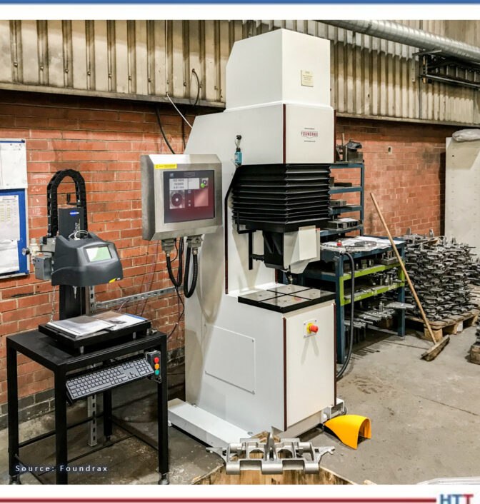
Figura 1. Robusto probador Brinell in situ

2. Contaminación de la superficie

Es poco probable que los contaminantes diminutos en una superficie generen una “prueba errónea” bajo un penetrador Brinell, a diferencia de la prueba de dureza Rockwell (el método más común en la industria). En esta prueba un pequeño indentador de diamante penetra menos de una centésima de pulgada, arrojando como resultado el que cualquier contaminante o anomalía en la superficie que pueda impedir o favorecer el progreso del penetrador (incluído el paralelismo) represente un problema, y obligando a que las muestras para la prueba Rockwell se deban preparar cuidadosamente antes de realizar la misma.

3. Portabilidad

Quizás el factor más significativo es que los robustos equipos portátiles de mano Brinell, con cabezales de prueba hidráulicos, permiten probar, in situ, piezas grandes, pesadas, de superficies rugosas o formas irregulares. Esta característica es de tal utilidad en la industria que ha motivado a que los órganos de normalización internacional otorguen una dispensación especial, una excepción si se quiere, a las máquinas portátiles, pese a que la ejecución de las mismas no sea susceptible de verificación directa como sí lo es la de sus equivalentes, las máquinas fijas.

Con fuerzas que van desde los 3000 kg hasta 1 kg, y bolas penetradoras tan pequeñas como 1 mm, las pruebas Brinell se pueden usar en una amplia gama de metales, pero los lugares en los que existiría la mayor probabilidad de encontrar un equipo de 10mm/3000kg son las forjas, las fundiciones, las plantas de tratamiento térmico, los laboratorios y las áreas de control de calidad. Previamente mencionamos que no se requiere que la superficie de las muestras de prueba sea absolutamente lisa; de hecho, es posible medir con un grado importante de precisión las superficies irregulares en materiales de configuración gruesa ya que el diámetro de la hendidura es tan grande en relación con cualquier irregularidad en la superficie.

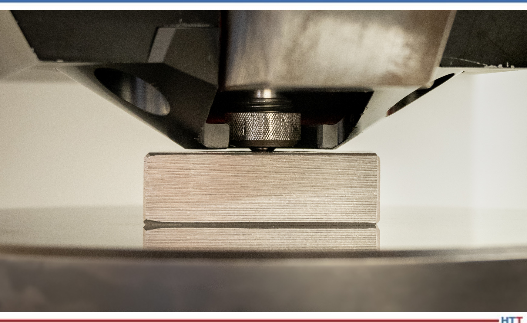
Figura 2. Probador de Brinell, grado calibrador, en primer plano

En la Figura 2 se puede apreciar cómo un probador Brinell de grado calibrador introduce la bola de carburo de tungsteno en la muestra de prueba. Se mantiene la bola en posición para estabilizar la deformación plástica.

Las normas que rigen de manera detallada las pruebas Brinell son la ASTM E-10 y la ISO 6506, pero el procedimiento práctico para los técnicos es muy sencillo, tanto que el entrenamiento no debería tardar más de una hora. Para ensayar piezas forjadas, palanquillas y otras muestras, una hendidura debería bastar aunque, desde luego, en ciertas aplicaciones de extrema importancia se podrá utilizar más de una para mayor seguridad.

Saber si analizar o no cada muestra en un lote determinado deberá decidirse con base en la inconsistencia de las muestras mismas, más no responde a problemática alguna con las pruebas de Brinell en sí. En ciertas industrias se prueba cada pieza que se produce debido a que el riesgo de error es demasiado alto. Un buen ejemplo lo encontramos en la producción de los componentes de los eslabones para las orugas utilizadas en tanques y maquinaria pesada (retroexcavadoras y demás). Cada eslabón de cada oruga de un tanque en uso en el ejército británico ha sido probado por Brinell en una máquina totalmente automática, de alta velocidad, que cuenta con una poderosa abrazadera integral para mantener el componente absolutamente rígido durante la prueba. Por cierto, esa máquina es la de la primera foto. Con un cuidado adecuado y razonable, un probador Brinell robusto podrá generar cientos de miles de pruebas; de hecho, el probador de la Figura 1 ha realizado varios millones.

Las pruebas duran aproximadamente quince segundos ya que el penetrador se debe dirigir hacia el material de manera uniforme sin permitir la posibilidad de un “rebote” y evitando por completo llegar a golpear el material. Por otro lado, el metal debe recibir la presión por un período de tiempo suficiente que garantice que la hendidura se deforme de la manera más plástica posible, es decir, minimizando al máximo el riesgo de la más ligera contracción de la hendidura una vez retirado el penetrador.

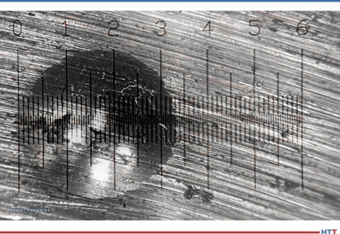
Figura 3. Medición de una hendidura de prueba de dureza Brinell

Sin embargo, es en este punto que se presentan las complicaciones. Después de generar cuidadosamente la hendidura y retirar la muestra de prueba de la “boca” de la máquina probadora, es necesario medir la hendidura en al menos dos diámetros. Dado que las hendiduras de Brinell tienen como máximo 6 mm de ancho y que una diferencia de 0,2 mm en el diámetro podría equivaler a 20 puntos de dureza, obtener la medición correcta es esencial y de alta complejidad. La mayoría de los técnicos usan un microscopio iluminado para lograrlo, pero aún así puede ser un desafío. Considere la Figura 3.

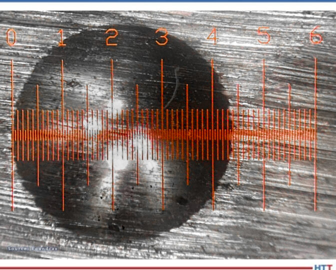
Los microscopios de medición manual han mejorado a lo largo de los años, y cuando se obtiene una hendidura relativamente “limpia” con una retícula nítidamente iluminada, se le puede facilitar al técnico experimentado realizar una medición precisa. La Figura 4 presenta un escenario menos complejo que el anterior pero, aun así, ¿cómo podemos saber si realmente se ha juzgado con precisión la posición del borde?

Figura 4. Medición con microscopio mejorado y retícula bien iluminada.

Al crearse la hendidura se genera un cordoncillo en el perímetro de la misma debido a que el metal no solo presiona hacia abajo, sino también hacia los lados. Este cordoncillo puede difi cultar la ubicación del punto en el que comienza realmente la hendidura, y tres técnicos diferentes pueden hacer fácilmente tres estimaciones diferentes de su lugar de inicio. Es esta variación en la interpretación de los resultados por parte de los operadores la que ha llevado a que, durante más de 80 años, la prueba Brinell se haya considerado un poco “ordinaria”, apta tal vez para el maquinista en el taller, pero de dudoso valor para el científi co en el laboratorio.

En 1982 llegó a los mercados el primer lector automático, siendo éste la culminación de años de investigación, y valiéndose de software privado que llevó a las computadoras de la época a sus límites. El equipo podía hacer cientos de mediciones de un lado a otro de la hendidura y calcular el diámetro medio en una fracción de segundo. Poco después llegó a ser parte integral de una máquina de prueba Brinell. La noticia de la aparición de este equipo pronto llegó a algunos usuarios importantes en la industria de las herramientas petroleras quienes exigieron a sus proveedores valerse de él; quince años más tarde se había diseminado ampliamente el uso de esta tecnología generando la transformación de la percepción que se tenía de la prueba Brinell. Podríamos decir que la prueba Brinell había llegado a la mayoría de edad.

Figura 5. La última versión de ese microscopio automático en acción

Desde luego, como con cualquier equipo de medición importante, la calibración y el mantenimiento regulares son aconsejables, si no obligatorios. Los fabricantes mismos suelen estipular un cronograma de mantenimiento que se debe tener en cuenta junto con las reglas de calibración establecidas por las agencias internacionales.

Al considerar las opciones para la prueba de dureza en muestras con tratamiento térmico, en última
instancia existen tres métodos: Brinell, Rockwell y Microdureza (Vickers o Knoop).

Pese a que no es adecuada para muestras muy pequeñas o demasiado delgadas, la prueba Brinell es relativamente “inmune” a los contaminantes pequeños, los penetradores no son costosos, y, gracias al ancho de la hendidura, las pruebas de superficies con acabado áspero e irregular no presentan dificultades. Con el desarrollo, hace 40 años, de la medición automática de la hendidura, se superó la única deficiencia grave de la prueba Brinell, proporcionando las garantías que tan vital importancia revestían para los proveedores de piezas esenciales en industrias de toda índole, incluídas las de petróleo y gas, aeroespaciales y de defensa y transporte.

Sobre el autor: Alex Austin se viene desempeñando desde 2002 como gerente de Foundrax Engineering Products Ltd. Foundrax es proveedor de equipos de prueba de dureza Brinell desde1948, siendo en realidad la única compañía en el mundo especializada en el campo.

Alex funge en el Comité de Prueba de Dureza por Hendidura ISE/101/05 del British Standards Institution. En su calidad de miembro de la delegación británica de la Organización Internacional de Normalización, ha aportado como consultor para el desarrollo de la norma ISO 6506 “Materiales metálicos–prueba de dureza Brinell” y preside en la actualidad la revisión ISO de dicha norma.

Mayor información en www.foundrax.co.uk


Find heat treating products and services when you search on Heat Treat Buyers Guide.com


El ensayo de dureza Brinell para principiantes Read More »

Exo Gas Composition Changes, Part 1: Production

Exothermic gas undergoes a few metamorphoses from the time it is produced to the time it is cooled down after use. Explore the transformations that occur within the combustion chamber to discover the impact these phases can have on the heat treatment atmosphere of your workpieces.

This Technical Tuesday article was composed by Harb Nayar, president and founder, TAT Technologies LLC. It appears in Heat Treat Today's August 2023 Automotive Heat Treating print edition.


Background

Harb Nayar
President and Founder
TAT Technologies LLC
Source: LinkedIn

Exothermic gas, more commonly referred to as Exo gas, is produced by partial combustion of hydrocarbon fuels with air in a well-insulated reaction or combustion chamber at temperatures well above 2000°F. Immediately after they exit the combustion chamber, the reaction products are cooled down using water to a temperature below ambient temperature to avoid condensation. The typical dew point of the cooled down Exo gas is about 10°F above the temperature of the water used to cool down. The cooled down Exo is then delivered to the heat treat furnaces where it gets reheated to the operating temperatures between 300°F and 2100°F.

Contact us with your Reader Feedback!

A simplified schematic flow diagram of Exo gas production followed by its cool down below ambient temperature and its final use in heat treat furnaces is shown in Figure 1.

The following aspects of the Exo gas production are clear from Figure 1:

  1. There is lot of energy lost out of the reaction chamber.
  2. There is additional heat lost during cooling using water.
  3. A good deal of water is used for cooling.
  4. The cooled down Exo gas is re-heated to the process temperature in heat treat furnaces.

Exo gas has been predominantly used and is still being used as a source of nitrogen rich atmosphere for purging, blanketing, and mildly oxide reducing applications in the heat treat and metal working industries.

Figure 1. Schematic flow diagram showing Exo production, cool down, and its use.
Source: Morris, “Exothermic Reactions,” 2023

Examples of applications:

  • Brazing
  • Annealing
  • Hardening
  • Normalizing
  • Sintering
  • Tempering, etc.

Examples of materials:

  • Irons
  • Steels
  • Electrical steels
  • Copper
  • Copper-base alloys
  • Aluminum
  • Jewelry alloys

Examples of product sizes and shapes:

  • Tubes
  • Rods
  • Coils
  • Sheets
  • Plates
  • Components
  • Small parts, etc.

Exo is the lowest cost gas used in furnaces operating at temperatures above about 700°F to keep air out and provide a protective atmosphere with some oxide reducing potential to the materials being thermally processed.

There are two types of Exo gases: lean Exo gas, with mostly nitrogen and carbon dioxide and very little hydrogen, and rich Exo gas, with a little less nitrogen and carbon dioxide and substantially more hydrogen and some carbon monoxide. Typical compositions are given below:

  • Lean Exo: 80–87% Nitrogen; 1–2% Hydrogen; 2–4% H20; 1–2% CO; 10–11% CO2
  • Rich Exo: 70–75% Nitrogen; 9–12% Hydrogen; 2–4% H20; 7–9% CO; 6–7% CO2
Figure 2. Exo gas operating range
Source: SECO/WARWICK

Figure 2 shows graphs of Exo gas composition at various air to natural gas ratios. H2, CO, and residual CH4 decreases with increasing air to natural gas ratio whereas CO2 goes in the opposite direction. H20 content not shown in the graphs is typically in the 2–4% range depending upon the temperature and cooling efficiency of the cooling system. N2 is the balance which increases with increasing air to natural gas ratio.

The generator designs to produce lean and rich Exo gases are slightly different as shown in the schematic flow diagrams below in Figures 3 and 4.

Objective

This paper will demonstrate a simplified software program (harb-9US) developed recently by TAT Technologies LLC that can easily calculate the reaction products composition, temperature, exothermic energy released, various ratios, and final dew point for various combinations of air and fuel flows entering the reaction chamber at a predetermined temperature and pressure.

The data presented in this paper is under thermodynamically equilibrium conditions only, captured when the reaction is fully completed. It does not tell how long it will take for the reaction to reach completion. However, it can be safely said that reactions are completed relatively fast at temperatures above about 1500°F and very slow at temperatures below about 1000°F. The current software program uses U.S. units: flow in SCFH, pressure in PSIG, temperature in degrees Fahrenheit, and heat as enthalpy in BTU.

The composition of the Exo gas for a fixed incoming air to hydrocarbon fuel ratio changes from production in the combustion chamber to the cool down equipment to bring the Exo gas to below the ambient temperature and finally into the furnace where the material is being heat treated.

Understanding the changes in gas composition from Step 1 (Production in the Combustion Chamber) to Step 2 (Cool Down to Ambient Temperature) to Step 3 (At Temperature of Heat Treated Part) can help to improve the composition, quality, and control of Exo gas that will surround the metallic products being heat treated in the furnace.

Figure 3. Lean Exo generator schematic flow diagram
Source: SECO/WARWICK

Step 1: Composition of Exo Gas as Produced in the Combustion Chamber

Table A shows the Exo gas compositions as generated within the combustion chamber at various air to natural gas ratios supplied at 100°F and 0.1 PSIG. In these calculations natural gas composition is assumed as 100% CH4 and air is assumed as 20.95% oxygen and balance nitrogen. CH4 is fixed at 100 SCFH and air flow is varied to give air to natural gas ratios between 9 and 6. Typically a ratio of 9 is used for lean Exo and 7 is used for rich Exo applications. Other ratios are used in some special applications.

Table A: Exo gas compositions in reaction chamber based on 100 SCFH of CH4 with air 900, 850, 800, 750, 700, 650, and 600 SCFH to give air to natural gas (CH4) ratios of 9, 8.5, 8, 7.5, 7, 6.5 and 6 respectively. Air and natural gas (CH4) are at 100°F before entering the combustion chamber.
Source: TAT Technologies LLC

The following key conclusions can be made from Table A as one moves from air to natural gas (CH4) ratio of 9 down to 6:

  1. The peak temperature in the reaction chambers goes from a high of 3721°F down to low of 2865°F. Because of high temperatures, good insulation around the combustion chamber is a must. A significant portion of the exothermally generated energy within the reaction chamber is lost to the surroundings.
  2. There is no residual CH4 in the Exo gas composition at these high temperatures. There is no soot (carbon residue) under equilibrium conditions.
  3. H20 content in the natural gas (CH4) gas in the reaction chamber is very high — from high of 19.11% to low of 15.87%. These correspond to dew point 139°F to 132°F — well above the ambient temperature. Because of the very high dew point, the Exo gas coming out of the reaction chamber must be cooled down below the ambient temperature to remove most of the H20 in the Exo gas to avoid any condensation in the pipes carrying the Exo gas toward the furnace and into the
    furnace.
  4. H2% changes significantly from 0.67% to 9.96%.
  5. The oxide reducing potential (ORP) as measured by H2/H20 ratio changes from a very low of 0.035 to 0.628. ORP in the reaction chamber is overall quite low because of high percentage of H20.
  6. Nitrogen content varies from 70.34% to 61.26% of the total Exo gas in the reaction chamber.
  7. Exothermic heat generated varies from 95.3 MBTU to 54.34 MBTU — it gradually becomes a less exothermic reaction. Gross heating value of CH4 (at full combustion) is 101.1 MBTU/100 cubic foot of CH4.
Figure 4: Rich Exo generator schematic flow diagram
Source: SECO/WARWICK

Question: What happens to the composition of Exo gas as it cools from peak temperature in the combustion chamber to different lower temperatures after it exits from the combustion chamber?

Answer: It changes a LOT, assuming enough time is provided to reach its equilibrium values during cooling down to any specific temperature. Whenever there is a mixture of gases, such as CH4, H2, H20, CO, CO2,O2, N2, there are a variety of reactions going on between the constituents in the reactant gases to produce different combinations of gas products and heats (absorbed or liberated) at different temperatures. The most popular and well-known reactions are:

  • Partial Oxidation Reaction: CH4+ 1/2O2 → CO + 2H2 — exothermic. The reaction becomes more exothermic as O2 increases from 0.5 to 2.
  • Water Gas Shift Reaction: CO + H20 → CO2 + H2 — slightly exothermic. It usually takes place at higher temperatures faster. A catalyst in the reaction chamber can help to lower the high temperature requirement. There are many catalysts. Commonly used are either Ni or precious metals.
  • Steam Reforming Reaction: CH4 + H20 → CO + 3H2 — highly endothermic.
  • CO2 Reforming Reaction: CH4 + CO2 → 2CO + 2H2 — endothermic.

All of these reactions have different degrees of influences from changes in temperature. One could say that the final equilibrium composition of the Exo gas is a continuously moving target as temperature changes. Only the N2 portion stays constant. One can make the following generalized statements covering a broad range of Exo gases (lean and rich) in the reaction chamber:

a) N2 content does not change. It remains neutral at all temperatures.
b) H2 content decreases with increasing temperature.
c) H20 (vapor) content increases with increasing temperature.
d) CO content increases with increasing temperature.
e) CO2 content decreases with increasing temperature.
f) Residual CH4 decreases with increasing temperature.
g) Soot decreases with increasing temperature.
h) Catalysts facilitate the speed of reactions at any temperature.

Conclusion

Exo gas composition changes during its time in the combustion chamber. Reaction products composition, temperature, exothermic energy released, various ratios, and final dew point are all items that need to be taken into consideration to protect the metallic pieces that will be heat treated in the resulting atmosphere. Part 2 will demonstrate this principle and discuss Step 2 (Cool Down to Ambient Temperature) and Step 3 (At Temperature of Heat Treated Part).

About the author:

Harb Nayar is the founder and president of TAT Technologies LLC. Harb is both an inquisitive learner and dynamic entrepreneur who will share his current interests in the powder metal industry, and what he anticipates for the future of the industry, especially where it bisects with heat treating

For more information:

Contact Harb at harb.nayar@tat-tech.com or visit www.tat-tech.com.

References:

Herring, Dan. “Exothermic Gas Generators: Forgotten Technology?” Industrial Heating, 2018. https://digital.bnpmedia.com/publication/m=11623&i=534828&p=121&ver=html5.

Morris, Art. “Exothermic Reactions.” Industrial Heating (June 10, 2023), https://www.industrialheating.com/articles/91142-exothermic-atmospheres.


Find heat treating products and services when you search on Heat Treat Buyers Guide.com


Exo Gas Composition Changes, Part 1: Production Read More »