Heat Treat Today would like to thank and celebrate all the veterans who have served and helped to make the United States a place of freedom and liberty. Thank you for your service and for your sacrifice.
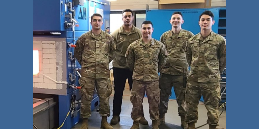
United States Air Force personnel stationed at Royal Air Force (RAF) Base Mildenhall in the United Kingdom recently commissioned and received full training on the use and maintenance of a heat treating furnace for aerospace parts. The furnace will help maintain KC-135, CV-22, C-130 aircraft, and F-15 fighter jets assigned to RAF Mildenhall or nearby RAF Lakenheath air stations. The installation was interrupted by an impromptu visit from the U.S. President.
Richard Conway Chief Technology Officer Delta H Technologies
The DELTA H® TECHNOLOGIES dual chamber heat treating furnace for aerospace (DCAHT®) was designed by the supplier to rapidly heat treat all common aviation grade metals and alloys necessary for aircraft maintenance and is fully compliant with USAF/NAVAIR Tech Order 1-1A-9 and SAE-AMS2750F. The training received by the USAF airmen at RAF Mildenhall included essential instructions in heat treating, as well as furnace calibration practices like temperature uniformity surveys (TUS) and system accuracy tests (SAT) and culminated with each airman receiving Certificates of Training.
The specialized furnace features an upper chamber convection system, 18" wide x 12" high x 48" deep, capable of Class 1 (+/-5°F) from 200°F to 1200°F and a lower chamber radiant heat system, 12" wide x 12" high x 36" deep, capable of Class 3 (+/-15°F) from 1000°F to 2000°F with air or argon atmosphere. A roll-away quench tank features dual baths for water and oil quenchant. The controls and data acquisition provide detailed batch records of heat treated parts, including quench delay, as well as automatic tracking of thermocouple usage and calibration intervals.
Air Force One at RAF Mildenhall
The training was interrupted by an unexpected visitor to RAF Mildenhall. The hangar next to the Metals Tech Shop, where the furnace was being commissioned and the training was being conducted, was the epicenter for the arrival of a top-secret VIP. When the Air Force Band began practicing "Hail to the Chief," it became obvious that U.S. President Joe Biden would be making an unexpected visit to the base. While the President’s visit was not related to the furnace commissioning, Richard Conway, DELTA H® founder and chief technology officer, and wife Mary Conway, witnessed this presidential visit and got a few candid photographs of Air Force One (see above).
On this Technical Tuesday, dive deep into this article to learn Industry 4.0 heat treating solutions to enduring problems. As author and captive heat treater Joseph Mitchell, director of Operations & Technology for The Miller Company, says, "These solutions have the capability to mitigate incessant (and costly) problems in our thermal and metal processing industry." Let's take a closer look at Industry 4.0 solutions to the problem of coil wraps "sticking" during batch annealing.
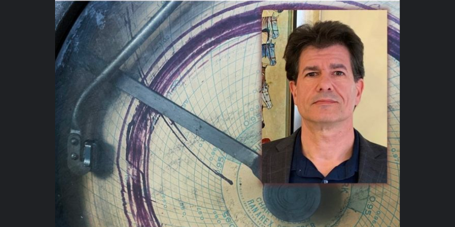
Joseph Mitchell Director of Operations & Technology The Miller Company
As US manufacturing recovers from the ill effects of a seemingly unremitting pandemic and corollary supply chain challenges, the advance of Industry 4.0 and Industrial Internet of Things (IIOT) necessitates manufacturing industries reevaluate their business practices. For maximum profitability, business "as usual" simply will no longer suffice. Jason Ryska, global chief engineer at Ford Motor Company, suggests even production behemoths overlook the obvious:
In many production processes, data analytics provides the agility to keep up with market trends and technology advancements. An exception to this trend is automotive production, a multi-billion-dollar industry that is underutilizing data collection and underestimating the potential improvement that may come from understanding the data being collected.
This quote is from a technical article written by Ryska in which he discusses current state and offers a glimpse of future state that is gained by a manufacturer investigating potential new solutions for old process problems by applying Industry 4.0 technologies.1
Metal industry leaders may ask, to the quote above, could we replace "automotive production" with "heat treating?" I believe there is a strong argument against such an exchange of words; however, in-depth examination at the plant level indicates deficiencies exist for the heat treating industry related to acceptance of IIOT technology and application of data analytics. Where do we observe the shortcomings? Perhaps, as suggested by Ryska, in our day-to-day comfort zone: "over reliance on employee experience and interpretation vs. physical measurements."
This keen insight into the current state of automotive manufacturing can be equally applied to different manufacturing landscapes throughout U.S. industry. Reviewing a familiar heat treating problem will help to illustrate the need for and applicability of digital monitoring and data collection for decision making and future development of advanced analytics like machine learning and AI. These solutions have the capability to mitigate incessant (and costly) problems in our thermal and metal processing industry.
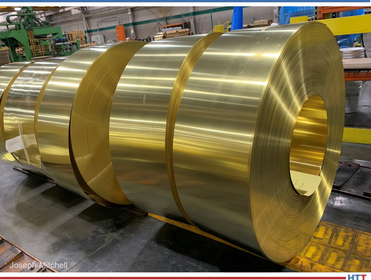
Yellow brass finished width coils; alloy C26800
Heat Treat Industry
In manufacturing, the same problems often occur again and again. In the metals industry, casting and thermal processing, in conjunction with continuing operations, present daily challenges to product quality. Troublesome and costly conundrums – like residual stress, distortion, cracking/poor forming in downstream operations, and poor surface quality/coating adhesion – occur regularly, causing waste, rework, late delivery, and lost profit.
Metallurgists, engineers, and technologists all understand the frustration of untold hours devoted to researching solutions to material processing problems. Some already have well known solutions while others may randomly appear seem, after causing much angst, to disappear (sometimes not as quickly as would be preferred). Regardless of that type of problem, the time, effort, and resources put into finding the solution cannot be redeemed.
The advance of Industry 4.0 and, more specifically, IIOT into modern manufacturing can provide our metal production sector the ultimate tools for unraveling costly and recurring quality issues. We understand this progression will be gradual and very slow.
Nonetheless, implementation of digital technologies is critical for our heat treating/materials processing industry. The fact CQI-9 4th ed. requires all instrumentation and process controls be digital by June 2023 supports the emphasis placed on eliminating analog based instruments and reengineering manufacturing processes for implementation of digital data collection and, thereby, steering heat treaters (automotive suppliers and, hopefully, non-automotive industrial heat treaters) toward eventual adoption of Industry 4.0 technologies.
In this article, we review a specific quandary typically encountered during batch annealing and examine why application of digital monitoring and data collection, and eventual integration of Industry 4.0 technologies, would facilitate understanding and assist in resolving the problem.
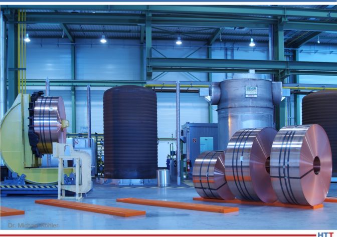
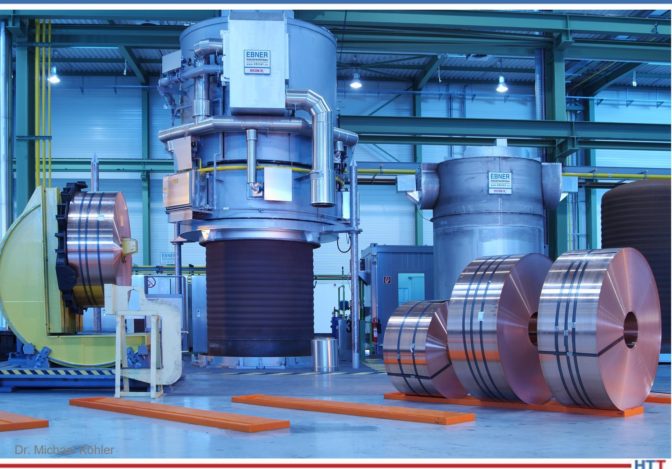
Typical gas fired bell annealing furnace; inner cover on base
Gas fired annealing furnace; heating bell being lowered into place
The Problem (Define)
A report, written in 1940 by T.J. Daniels, titled "The Prevention of Sticking in Bright Annealing Sheet Steel" is interesting for many reasons, and, for purpose of this article, provides an example of an early 20th century heat treating headache which, unfortunately, is still with us in the present century.2
The report consists of two parts:
Part I - Investigation of Factors Influencing Sticking
Pressure
Annealing temperature
Length of time at temperature
Part II - Prevention of Sticking
Multiple varieties of trial suspensions tested
Temperature, pressure, and time held constant for each test
Trials performed 2x each
Trials performed 3x for promising suspensions
Despite the efforts and subsequent process improvements in heat treating and manufacturing processes as discussed in Daniels' report, we find the following, equally interesting 21st century report, addressing the same subject in Hot and Cold Rolling Processes, Sticking and Scratching Problems After Batch Annealing, Including Coil Compression Stress Effects, by J.J. Bertrandie, L. Bordignon, P.D. Putz, and G. Volger.3
This 2006 report discusses the same sticking phenomenon (coil wraps adhering together after batch annealing) and expands its research into an accompanying quality problem that may occur in conjunction with or subsequent to batch annealing: material scratching. The report documents field trials and laboratory investigations.
The amount of investigative work described in this second report is noteworthy and the results provide data-backed conclusions. However, the problem addressed, potential causes studied, and solutions prescribed did not eliminate the phenomenon of sticking following batch anneal of ferrous and nonferrous coils. Fast-forward fifteen years to 2021 and the sticking phenomenon remains a topic of discussion (and source of grief) for heat treaters across continents.
My experience with a heat treater located in the Midwest, who occasionally encountered coil wraps sticking together during batch anneal of sheet steel, resulted in experiments with anti-sticking agents applied using a spray system, as well as studies for improved control of cooling the furnace charge. The cooling temperature gradient influences contraction of outer wraps which, if pressure is excessive, may result in wrap adhesion (cementation): growth of crystals across material wraps.
Although sporadic, costs were significant when sticking occurred. Unfortunately, the success of our experiments was limited due to time constraints and production requirements (nothing new here). As we know, a hit-or-miss success rate is not good for business; consequently, continuous improvement (CI) must be built into the system. Fortunately, technology is allowing this CI business approach by way of Industry 4.0.
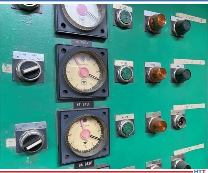
Per CQI-9 rev. 4, analog process monitoring is coming to an end
Descriptive Analytics (Measure)
I first will acknowledge many industrial processing plants operate using, shall we say, not exactly new or sufficiently updated equipment. Also acknowledged is the necessity of skilled and experienced personnel for monitoring and performing critical tasks. Nonetheless, with all else being equal, the fact this quality defect persists suggests industrial heat treaters need new solution for this old and burdensome problem. In short, transformation to digital technologies must occur in the metals processing industry for improved understanding and resolution of regularly occurring problems coming from complex manufacturing/processing systems.
At minimum, for study and resolution of our sticking problem, I recommend a supervisory control and data acquisition system (SCADA). Management should have "eyes" on the process at all times. SCADA allows digital process monitoring (real-time), process alarms (out-of-spec parameters), and automatic control (process adjustment) that will help improve process control at site location or via remote access. Likewise, data acquisition for historical review is critical for answering the question, "what happened and when?"
Digital collection and transfer of data (cloud-based or in-house server) and use of statistical analysis (data analytics) will help a company improve production through the development of predictive maintenance models, building understanding of equipment capability for effective and efficient processing, and defining key process parameters for best quality.
SCADA may be incrementally introduced into a manufacturing system (e.g., a single bell/box annealing furnace) and scaled accordingly. Another strategy is investment in IIOT technology software/apps/system. My experience includes investigation of IIOT as a service with MindSphere. This technology is scalable and can be integrated with legacy equipment for eventual connection with both old and new machines/processes. This is a more practical option considering few small-to-midsize heat treaters have cash for an all-at-once approach.
During initial installation stages, be sure to capture key process variables and the need for strategic placement of data gathering sensors based upon best opportunities for process impact like:
furnace atmosphere / time / temperature
material cleanliness / required microstructure / coil tension
strip thickness / strip width / process routing / pre & post processing
Data input from locations other than annealing furnace are of equal concern:
As noted earlier, I understand use of equipment that is in disrepair or outdated is a reality for some heat treaters; fortunately, use of SCADA system would provide necessary data to justify purchasing new equipment and/or upgrading old equipment. A data driven proposal presented in unbiased digital format is an advantage for showing upper-management current state-of-affairs and possible return on investment (ROI) if funding is provided and investments are made.
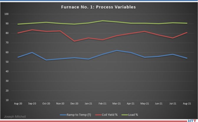
Digital monitoring of process variables: easy access of data for historical review and troubleshooting
Diagnostic Analytics (Analyze)
At this point, we have a SCADA (or similar) system in place, either for a given furnace/machine, work-cell, or eventually for an entire manufacturing/processing system. In our case, the process parameters associated with sticking, and therefore the ones which need to be monitored, include temperature, time, pressure, surface condition, and reactivity.4 The stage for descriptive analytics is set; data is collected/summarized, but no direct decisions/predictions develop from this digital data stream. We learn "what happened” and proceed with the question, "why" did "X" happen? Thereby, we enter the world of diagnostic analytics in the quest for root causes, seeking to understand unusual events: why did no sticking occur when we processed alloy "A" last week, but this week alloy "A" exhibits sticking?
Following our statistical study used in descriptive and diagnostic analysis that was performed using data analysis software, we continue applying statistical methods for our investigation. The objective is discovery and confirmation of relationships and/or trends, which may relate to, or show causes for, sticking (coil wraps adhering together).
Predictive Analytics (Improve)
Rarely in a heat treating/material processing dilemma is the root cause readily disclosed; my experience in heat treating is that "bad" phenomenon often occur and disappear with impunity, leaving root cause analysis a moot point. We breathe a sigh of relief and enjoy the quiet before the next storm.
In the past, this unfortunate scenario likely resulted from one of two things: first, the inability to measure multiple variables simultaneously; and second, if a system is in place identifying and monitoring key variables, then management's inability of correlating (note: correlation may not ≠ causation) effects of multiple process variables. This inability leads to dependency and/or relationships preventing meaningful and/or accurate interpretation of data. At best, this does no more harm than allow the continued ill-effects of current problem, but at worst, it leads to incorrect conclusions, possible worsening of the problem at hand, and new problems.
Here is where management of forward-thinking companies -- focused on developing optimal manufacturing efficiencies, equipment effectiveness, increased profit, and competitive advantage --differentiate themselves by advocating application of digital technologies. In this case, it means moving toward artificial intelligence (AI); smart machines/machine learning.
Many options related to machine learning software and machine connectiveness are available (e.g., Siemens, GE Digital, Samsara, etc.). Your SCADA system provider is a great place for beginning investigation into predictive/prescriptive software solutions using machine learning tools.
Another example of a systems approach for digital transformation is Smart Prod ACTIVE. Profiled in Foundry Trade Journal last winter, this information and communication technology (ICT) platform, designed for optimizing foundry production, illustrates the growing possibilities for increased competitive advantage and profit growth based upon implementation of digital technologies, such as EnginSoft - smart ProdACTIVE.5
Prescriptive Analytics (Control)
Heat treating consists of many interrelated processes and/or systems. Prescriptive analytics, by way of simulation software/modeling tools, leads to applicable solutions; as Luigi Vanfretti, an associate professor of electrical, computer, and systems engineering at Rensselaer Polytechnic Institute, states, "You need to have a way to understand the interaction of the systems, and, in an integrated way, you need to optimize them together."6
Digital data collection and advanced analytics open the door for data-driven decisions and improved understanding of a process. When we are able to investigate cause-effect relationship(s) and our modeling tools suggest appropriate/optimal adjustment for non-normal process variation, we can achieve standardization of a given heat treating process, possibly even aimed at specific equipment in a manufacturing system.
In other words, the optimization factors of bell furnace "A" may not be optimal for bell furnace "B." The parameters for various aspects of the manufacturing system may need adjustment based on equipment performance/condition or other factors (e.g., coil mass, time at soak temperature, surface roughness (rolls), incoming strip cleanliness, etc.).
In this manner, continuous improvement throughout the manufacturing system becomes a part of our day-to-day business.
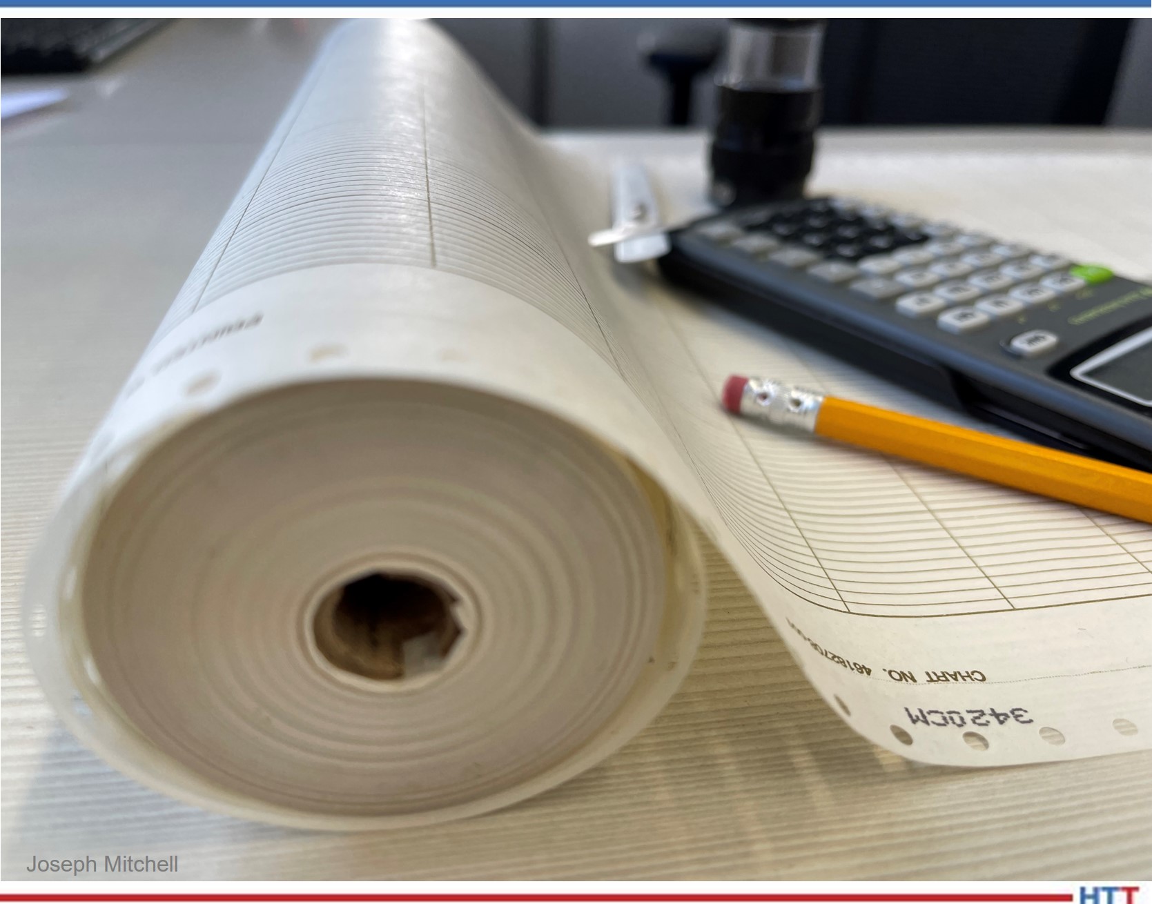
Chart recording; still valid, but not user friendly for data retrieval and statistical analysis
Digital Integration/Transformation
We examined a 21st century approach for resolving a 20th century problem: coil wraps sticking together post-anneal. This material processing phenomenon typically encountered when batch annealing ferrous or nonferrous materials may result from many interrelated process variables; that is, one or more sources of non-normal variation within a thermal processing system and/or manufacturing process.
The heat treating system, as well as the manufacturing system which is comprised of numerous material processes both upstream and downstream, requires continuous monitoring. As supported by CQI-9 (4th ed.), digital instrumentation is deemed necessary (for automotive suppliers) for surveillance and documentation of thermal processing parameters. Acquisition of digital data (e.g., SCADA) facilitates advanced analytics for predicting process outcomes and thereby prescribing optimal solutions which lead to process improvements.
Thus, application of digital monitoring/data collection, advanced analytics, and integration of Industry 4.0 technologies will enhance understanding, provide heretofore unknown process correlations/relationships, and thereby lead to problem mitigation.
As we close this article, some may ask, is digital transformation essential in our heat treating industry? Is IIOT and the all-encompassing Industry 4.0 a necessity for industrial heat treaters and others involved in material processing?
Perhaps a well-worn quote from W. Edwards Deming provides our answer: "It is not necessary to change. Survival is not mandatory."
About the Author: Joseph Mitchell is director of Operations & Technology for The Miller Company, a service slitting center which supplies bronze and specialty copper alloy precision metal strip. With a BS in Industrial Management and MBA from Lawrence Technological University, his interests include metallurgy and practical application of Industry 4.0 concepts/digital technologies for developing business strategy that provide optimal use of assets, energy, and process controls within the metals and automotive industry.
References
1 J. Ryska, Industry 4.0 Meets the Stamping Line - Ford Motor Company's stamping division looks to leap into Industry 4.0 the same way Henry Ford led the transformation from Industry 1.0 to 2.0, Advanced Materials and Processes, Feb/Mar 2020, Vol 178, NO 2, p 25-28.
2 T. Daniels, "The Prevention of Sticking in Bright Annealing Sheet Steel,” Thesis; submitted for degree requirements, MS Chemical Engineering, Georgia School of Technology.
Heat treating any aerospace projects? Then you know titanium is up there when it comes to VIP alloys in the industry. This best of the web is pulled from an aerospace magazine in which Michael Johnson of Solar Atmospheres answers five questions about creep flattening titanium:
Typical temperatures for creep flattening titanium parts
Whether of not creep flattening can only be done in a vacuum
Best fixturing for creep flattening titanium parts
Can creep flattening minimize movement
Will reheating titanium over 1,000°F affect certification
An excerpt:
"Give your heat treater your material certifications. Many mills will certify to aerospace material specification AMS 2801, AMS 4905, AMS 4911, AMS-H-81200, etc. The material often can be re-annealed while simultaneously creep flattening." - Michael Johnson, Director of Sales, Solar Atmospheres
A European machinery group will receive a vacuum furnace for hardening and tempering processes, and its design has been customized in order to meet the group’s need to harden aviation steel used as landing gear. The heat treatment solution will improve the process economy in European plants and is characterized, in part, by low energy consumption.
Maciej Korecki Vice President of Business for the Vacuum Furnace Segment SECO/WARWICK
To meet this particular application, SECO/WARWICK engineers fitted the Vector® vacuum furnace with a non-standard system for subquenching with liquid nitrogen that enables the required quick cooling down of landing gear components. The solution has also been expanded with a vacuum system designed with a diffusion pump and is equipped with a directional cooling option and convection heating system with a specially designed fan.
“This is already the fourth purchase order for a furnace from this product segment from this customer,” commented Maciej Korecki, VP of Business Segment for Vacuum Heat Treatment Furnaces at SECO/WARWICK, the sister company to North American heat treat supplier SECO/VACUUM. He also added that “The product solves the customer’s problem with the hardening of special aviation steel, significantly increases the capacity of the existing production line of this component, and also improves process parameters, since the current devices used by the customer are not fitted with a subquenching system using liquid nitrogen. It will certainly be one of the unique solutions completed this year.”
Heat Treat Today publishes eight print magazines a year, and included in each is a letter from the publisher, Doug Glenn. This letter first appeared in Heat Treat Today'sAugust 2021 Automotive print edition.
Doug Glenn Publisher and Founder Heat TreatToday
For those who might not know, AISTech is the annual conference produced by AIST, the Association of Iron & Steel Technology (www.aist.org), under the executive directorship of Ronald Ashburn and his capable staff, most of whom work out of Cranberry Township, Pennsylvania, just north of Pittsburgh and less than one hour from where I live (Go Steelers!). AISTech was not held in 2020 due to the response to COVID-19, but it was held this year in Nashville, Tennessee, on June 29 through July 1.
Here’s what I learned at AISTech this year:
(1)The steel industry is a rugged lot. Unsurprisingly, the men and women of the North American steel industry are not easily daunted. COVID hit many industries hard, and steel is no exception, but the folks in this industry are still up and swinging. Granted, the governors of most states deemed the steel industry as “essential” for COVID purposes (with the concept of governments identifying some industries as essential and others not being a topic for another day!) thus, most of the steel industry stayed active throughout 2020.
The fact is, the steel industry is a resilient and innovative lot, even in the midst of oppressive government restrictions on pretty much the entire economy. No where was that more evident than in Nashville. According to official numbers, roughly half of the usual 8,000ish attendees to AISTech were in Nashville. A pretty decent turnout considering that AISTech was one of the first significant face-to-face events to return to Nashville. Nashville was certainly happy to host the event and many from the steel industry showed up in person, without many masks or much social distancing, to enjoy a return to relative normal.
(2) The U.S. steel industry is one of the most innovative and aggressive in the world. The keynote speaker and this year’s recipient of the Steelmaker of the Year award, chairman, president, and CEO of Cleveland-Cliffs, Lourenco Goncalves, who has a column in this issue of Heat Treat Today (see page 8), explained that when it comes to steelmaking, no country on the planet holds a candle to the United States, especially when it comes to the amount of CO2 produced for each ton of steel created.
(3) During the press conference which followed the President’s Award Breakfast on June 30th, I asked Mr. Goncalves to comment on the use of hydrogen combustion. He took me to school (in a very gracious way) on the fact that hydrogen combustion, while not an emerging technology to be ignored, was not something commercially viable in the North American steelmaking industry and probably won’t be for many years.
In Europe, where the abundance of natural gas is not so great, hydrogen might be a more viable option in the near future, but that’s not likely to be the case here in North America where natural gas is abundant and relatively cheap. He also pointed out that a large constituent of natural gas is hydrogen, so in one sense, the North American steelmaking industry is already heavily invested in hydrogen, just not 100% hydrogen.
(4) Finally, I learned that (sorry aluminum fans) it is steel’s “game to lose” when it comes to which material will be used most heavily in the future of the North American automotive industry. While aluminum body panels have been popular of late, the fact is that steel “owns” the vast majority of automobile manufacturing and will continue to do so for two reasons: 1) the development of high-strength steels, and 2) the fact that it takes exceedingly less energy and the creation of vastly less CO2 to produce a ton of steel vs. a ton of aluminum. If you’re truly “green,” steel is the (unlikely) way to go.
I leave you with this. The July 2021 Investors Presentation which is publicly available on Cleveland-Cliffs’ website has a lot of very, very interesting information not only about the company, but about the North American steel industry as it compares to other countries and how steel compares to other materials such as aluminum, composites, etc. I recommend it for those who have more than a casual interest in steel. View the report here.
How can steel production be "green"? Where does the United States stand in steel production when compared to the rest of the world?
Lourenco Goncalves, chairman, president, and CEO of Cleveland-Cliffs, Inc. answers these questions and more in this article, originally published in Heat TreatToday'sAugust 2021 Automotiveprint edition.
Lourenco Goncalves Chairman, President, CEO Cleveland-Cliffs, Inc.
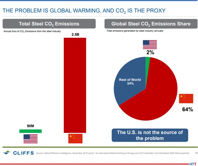
The United States is the benchmark of the world in all things steel. Amongst all major steelmaking nations, we have by far the greenest emissions profile. On average, each ton of steel produced in the United States generates 1.0 tons of CO2 emissions, compared to a ton of steel produced by China which generates 2.5 tons of CO2 emissions. The U.S. generates only 2% of all the greenhouse gas emissions from global steel production, while China contributes 64%.
The attributes that make our industry so green are the use of scrap, natural gas as both a reductant and energy source, and green iron ore pellets in blast furnaces. Because scrap cannot be used in a closed loop, natural gas and pellets allow for a healthy participation of low-carbon intensity virgin iron and steel units in a well-balanced ecosystem.
Steel’s emissions profile also makes it the lowest-carbon option compared to other materials perceived to be green, such as aluminum and carbon fiber. Adjusting for part weight, production of the equivalent volume of these competing materials generates 5 to 10 times more CO2 emissions than steel made in the United States.
This emissions profile is just one of many attributes that will support steel’s continued position as the material of choice in automotive light vehicle bodies. On top of being the greenest material and having a 100-year incumbency advantage, steel is more affordable than aluminum and is easier to weld, form, and repair or replace. Our continued innovation in advanced high strength steels (AHSS) has allowed us to produce thinner, lighter-weight, yet stronger materials, and closed the gap on the perceived density advantages that the aluminum industry has touted.
Even though we boast a low emissions profile, our work is not done. At Cleveland-Cliffs, we have made public our target to reduce greenhouse gas emissions by 25% by 2030. In our global discussion about decarbonization, the use of hydrogen (H2) as an iron-reducing agent has emerged as playing a key role in a carbon neutral future. While clean and leaving only steam (H2O) as its byproduct, large scale H2 use in steelmaking is an unproven technology that comes with enormous practical challenges, including safety and prohibitive costs. Knowing what we know today, we are probably decades away from H2 becoming part of any affordable and easily available technology.
At Cliffs, we don’t want to rely on breakthrough technologies, but rather deal with practical decarbonization options. Our efforts involve the use of the hydrogen contained in natural gas, which is actually a mix of 95% CH4 and 4% C2H6. Natural gas is used as the reducing agent at our new, state-of-the-art DRI facility in Toledo, OH, as well as a meaningful supplemental reductant in all eight of our blast furnaces. The abundance of cheap natural gas in the United States will continue to provide us ample opportunity to decarbonize.
Steel is the inevitable material of choice in a modern, greener world. As the largest flat-rolled steel producer in North America, Cleveland-Cliffs will remain on the cutting edge in shaping the future and further cementing our industry as the envy of the world.
About the Author: Lourenco Goncalves is chairman, president, and CEO of Cleveland-Cliffs, Inc.
Paulo Products was the recipient of the Commercial Heat Treater of the Year award presented by Heat Treat Today, in cooperation with The Metal Treating Institute (MTI). The award was initially decided and presented virtually in 2020, and was formally awarded in person on October 6, 2021 during the MTI Annual Fall Meeting awards banquet in San Antonio, Texas.
MTI awards the Commercial Heat Treater of the Year to the company that demonstrates they are making a positive impact in the community and the industry. The award is judged by a panel of previous recipients based on quality programs, pollution and hazardous waste control, community involvement, and leadership.
The award consists of a plaque and a $1,500 donation to the MTI Educational Foundation by Heat Treat Today in the name of the winning company. The donation was matched by MTI’s Educational Foundation. Paulo Products will award this $3,000 as a scholarship to a high school or college student pursuing an education towards heat treat.
Photo: Paulo Products being recognized as 2020 Commercial Heat Treater of the Year. (L-R) Jim Oakes, Super Systems, Inc. & MTI President; Will and Ben Rassieur Paulo Products; Doug Glenn, Heat Treat Today
Welcome to another Technical Tuesday for 18 hard-hitting resources to use at your heat treat shop. These include quick tables, data sets, and videos/downloadable reports covering a range of heat treat topics from case hardening and thermocouples to HIPing and powder metallurgy.
Defining Terms: Tables and Lists
Table #3 Suggested Tests and Frequencies for a Polymer Quench Solution (in article here)
Case Hardening Process Equipment Considerations (bottom of the article here)
Two simulations of a moving billet through heating systems (in article here)
Fourier’s Law of Heat Conduction (in article here)
Webinar on Parts Washing (link to full webinar at the top of the review article here)
Materials 101 Series from Mega Mechatronics, Part 4, Heat Treatment/Hardening here
Heat Treat TV: Press-and-Sinter Powder Metallurgy here
BONUS: 39 Top Heat Treat Resources
Heat Treat Today is always on the hunt for cutting-edge heat treat technology, trends, and resources that will help our audience become better informed. To find the top resources being used in the industry, we asked your colleagues. Discover their go-to resources that help them to hone their skills in the 39 Top Heat Treat Resources on this page of the September print magazine.
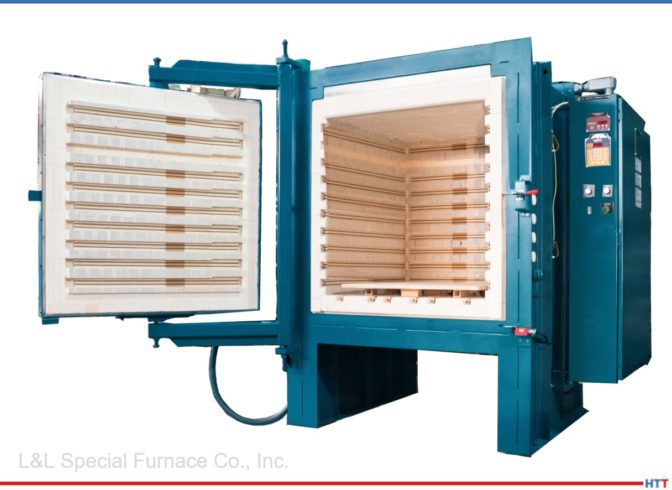
A high-uniformity box furnace has been delivered to Soil Lab, a community-based workshop based in Chicago, as part of the 2021 Chicago Architecture Biennial. The furnace received a fast-track shipment of four weeks to be part of the biennial workshop program in which local community groups will experiment and gain knowledge of ceramic production and various processes.
TheL&L Special Furnace Co., Inc. Model XLE 3636 is a front-loading, refractory-lined box furnace and has an effective work zone of 34” wide by 34" high by 32" deep. There is a horizontal double pivot door with a safety power cutoff switch. A ceramic hearth and standoffs are provided as a workspace for various ceramics and ceramic-based products. Additionally, the furnace has a series of inlets on the side and an outlet on the top. These can be capped off when not in use to preserve heat, and can provide a "candling" effect where various ceramic byproducts can be removed from the furnace. Some of these byproducts can be corrosive and need to be removed from the system.
Pictured in the main image above: Soil Lab team photo, (L to R) Vester, Bruun, Martin, Ni Chathasaigh