FIXTURE RACKING SYSTEMS TECHNICAL CONTENT

Optimize Working Life and Performance of Heat Treatment Alloy Castings

When it comes to optimizing the working life and overall performance of heat treatment alloy castings, proper alloy selection and design based on the intended application is a critical starting point. Discover the variables behind alloy selection and design and the additional factors that contribute: furnace maintenance, casting inspection, and cost reduction strategies.

This Technical Tuesday article was composed by Matthew Fischer, manager of Technical Sales, Castalloy Group for Heat Treat Today's August 2023 Automotive Heat Treating print edition.


Alloy Selection and Design Criteria 

Matthew Fischer
Manager of Technical Sales for Heat Resistant Products
Castalloy Group NA
Source: Castalloy Group

Optimal design and alloy composition for any heat treatment casting always requires careful consideration of a number of key operating variables. This is the only way to guarantee the part will deliver maximum utilization and efficiency for the intended application.

These variables include:

  • Anticipated service and maximum operating temperature
  • Size, orientation, and weight of the load
  • Thermal cycling and/or quenching
  • Range of temperature cycling
  • Frequency of temperature cycling
  • Rate of change of temperature
  • Type of atmosphere or other corrosive conditions of the application
  • Type of quenching or cooling
  • Size, shape, and weight of part(s)
  • How are the parts loaded and oriented? (e.g., manually, robotically, individually, bulk)
  • How is the alloy supported in the equipment? (e.g., rails, hearth, rollers, piers)
  • Additional processing requirements (e.g., machining, welding)
  • Abrasive or wear conditions
  • Ease of use (ergonomics) and replacement
  • Cost — initial and total cost of ownership

Contact us with your Reader Feedback!

In addition, there are fundamental factors that heavily influence optimal component design and alloy composition. For instance, the type of furnace used (e.g., box, pit, integral quench, continuous), alloy handling mechanism (fixture and tray), and application process (e.g., carburizing, normalizing, annealing, austempering, vacuum heat treating) all have an important role to play. It is worth noting, however, that the decision-making process is a fine balancing act that isn’t necessarily evenly weighted. While a specific alloy composition may Fiaddress the majority of performance needs, it may hinder others. Prioritizing end-use performance traits is therefore essential.

Furnace and Process Environment Maintenance 
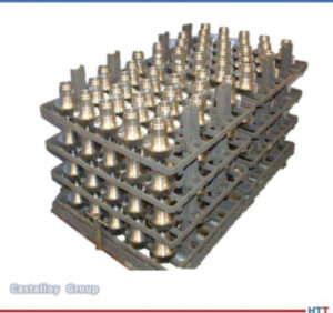
Figure 1. Cast tray and fixtures
Source: Castalloy Group

How furnaces and processes are performance monitored and maintained is also key when seeking to optimize the performance and lifespan of heat treatment alloy castings. The specific type of furnace will dictate exact equipment and process maintenance requirements, but there are several universal best practice procedures and guidance processes that should be followed.

For instance, the Automotive Industry Action Group (AIAG) has established CQI-9 (Continuous Quality Improvement) standards for heat treatment. These standards provide the guidelines for a continuous cycle of assessment, planning, and improvement with respect to heat treat processing and due care of handling customer parts. The CQI-9 standards direct the heat treater to have and maintain the necessary equipment and associated control instruments used to monitor and record the furnace process operating parameters. They also promote the proper furnace operating process environment. However, the standards do not comprehensively address the overall maintenance requirements of the furnace and process environment equipment. Generally, yearly scheduled maintenance is important to the long-term successful continuous operation of furnace equipment. Lack of or intermittent maintenance can lead to unplanned shutdowns. Here are some of the most common maintenance issues to monitor and remedy:

Example 1: Support Misalignment

If base tray support mechanisms are in alignment (in the direction of travel) and flat (level throughout) to provide proper support of the base tray and associated fixtures and parts, then the tray should move through the furnace equipment without issue, provided the tray is in good operating condition. However, if there are broken rails or piers — or broken/deformed roller rails or wheels — then over time the tray may exhibit wear, deformation, cracks, or breaks.

Example 2: Transfer Mechanism Misalignment

If the transfer mechanisms are square to the tray (in the direction of travel) and level throughout, providing proper contact with the base tray, then the tray should move through the furnace equipment without issues, provided the tray is in good operating condition. However, if there are misaligned transfer mechanisms (pusher rods, pusher head, handler head etc.), then over time the tray may exhibit associated wear, deformation, distortion, cracks, or breaks.
Figure 2. Flat level surface and tray/grid
Source: Castalloy Group

Example 3: Uneven Heating

Although the furnace may be able to maintain an average furnace temperature as measured by a single control thermocouple, there may be uneven heating conditions (side-to-side, top-to-bottom, front-to back) due to a variety of factors, which could result in uneven thermal cycling of the alloy castings. This potential non-uniform heating of the alloy could lead to deformation, cracks, or breaks of the alloy castings. The CQI-9 standards work to monitor and address non-uniform heating using a periodic temperature uniformity survey (TUS) of the furnace heating chamber.
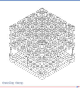
Figure 3. Example of original supplied alloy casting for comparison.
Source: Castalloy Group

Example 4: Non-Uniform Cooling

Although the quench chamber may be able to maintain an average quench medium temperature as measured by a control thermocouple, there may be uneven cooling conditions within a load due to a variety of factors, which could result in uneven thermal cycling of the alloy castings. If left unchecked, any of these issues may result in unintended wear, deformation, distortion, cracks, or breaks of the alloy castings. Furnace material handling issues may also result in an unplanned equipment downtime and productivity loss.

Alloy Castings Inspection

Alloy castings (fixtures, trays, grids) should be inspected periodically to ensure they are in adequate working order. This inspection could be performed when the furnace equipment is taken out of operation for summer or winter maintenance inspections and shutdowns. The main areas to consider are flatness, squareness, and proper proportion.
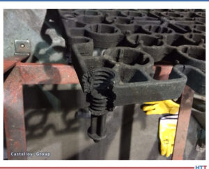
Damaged component
Source: Castalloy Group

Flatness

Trays, grids, and fixtures should remain flat or level across the width and length. Sagging, bowing, warping, or twisting can cause material handling issues within furnaces and associated process equipment. A simple method to check the flatness is to have a table with a flat and level surface where the tray, grid, or fixture may be placed to check and observe the flatness of the alloy casting. An alternate method to check the alloy casting flatness would be to use a level across the casting to check flatness.

Squareness

Trays, grids, and fixtures should remain square across the width and length. Being out of square can cause material handling issues within furnaces and associated process equipment. A simple method to check the squareness is to have carpenter’s square tool where the tray, grid, or fixture may be examined to observe the squareness of the alloy casting.

If the tray used in the heat treatment equipment is an assembly of trays, then each tray should be examined for squareness in all four corners. Trays that are out of square may cause tracking problems in the material handling of the furnace, or associated equipment, and should be replaced.
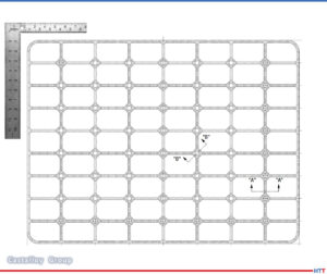
Figure 4. Square tool and tray/grid
Source: Castalloy Group

Proper Proportion

Trays, grids, and fixtures should remain in proper proportion as originally designed. Having bulges or large breaks that are outside of the alloy dimensional alignment compared with the originally supplied alloy casting can cause material handling issues within furnaces and associated equipment. A simple method to check the dimensional proportion is to have a picture or drawing of the originally supplied alloy casting. The tray, grid, or fixture can be compared with this in order to observe the overall soundness of the alloy casting. Suspect castings should be removed from daily operation to prevent potential material handling and associated equipment maintenance issues. An alternative to visual inspection is to make a simple jig that can be used to confirm the dimensional integrity of the alloy casting. Observable patterns of proportional changes within a common area of the alloy castings may indicate a potential issue occurring within the heat treat equipment that should be monitored and investigated before it becomes a major equipment issue and causes an unplanned equipment shutdown.

Optimizing Alloy Castings Using Periodic Purchases
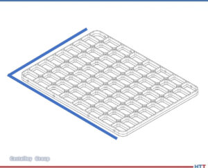
Figure 5. Jig tool to check proportion
Source: Castalloy Group

Periodic purchases of alloy castings should be planned and budgeted annually to maximize casting working life, to minimize process interruptions due to potentially expired useful life of alloy castings, and to manage future expenditures for replacement alloy casting purchases.

In general, budgeting for a percentage of alloy purchases over a two to three- year period, depending on current and planned future operations, would be supportive of continuous production operations. The periodic alloy purchase is then integrated into the existing production operations and suspect alloy castings, if any, can be removed from daily production operations.

There are multiple approaches that can be implemented and adjusted according to individual plant production needs:

One approach to consider is the purchase of one-third of the total alloy purchase per year over the following three years after an initial purchase. In a continuous daily production operation, the initial purchased quantity of alloy castings will have been replaced, if needed, over the elapsed time.

An alternate approach to consider is a staggered percentage over three years. For example, 20–25% replacement the first year; 30–35% replacement the second year; 35–40% replacement the third year, adjusted as necessary based on current operating and business conditions.

This approach would also be useful for ramping up alloy quantity needs to meet increasing demand over time and could be an opportunity to address potential delivery time requirements with coordinated planned periodic purchases.

Additionally, intermixing newly purchased alloy castings along with production alloy castings, may provide for extended life for the latter.

Scrap Alloy Recycling: New Alloy Purchase Credit for Returning Your Scrap Alloy Material

When alloy castings are no longer usable in daily heat treatment operations, it can be advantageous to sell them back as scrap to the alloy supplier. The supplier should be able to provide a scrap repurchase credit that can be used for future purchases of new alloy castings.
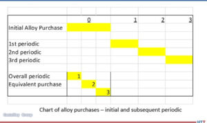
Figure 6. Visual demonstration of capital flow for initial and subsequent alloy purchases
Source: Castalloy Group

Generally, this scrap alloy repurchase credit may be used in whole or in part as directed by the customer for new replacement alloy casting purchases.

As well as being cost-efficient, scrap alloy castings recycling supports the long-term sustainable use of metals, minimizes the potential negative impact on the earth’s environment, and reduces the overall carbon footprint of both alloy user and supplier.

Summary
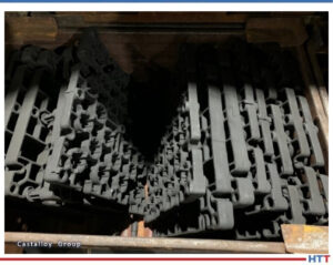
Figure 7. Typical scrap alloy trays and grids
Source: Castalloy Group

To review, improving the working life of heat treating cast alloys starts with design and is maintained with factors that account for the full alloy casting life:

  • Choosing the right design and alloy composition for heat treatment castings is fundamental to optimizing their working longevity and performance. This decision can only be made by carefully considering key aspects of the intended casting
  • Maintaining furnace equipment and process environment operating conditions will also assist in maximizing the working life and overall performance of the alloy castings.
  • Alloy casting inspection will support heat treat operations and minimize potential equipment downtime by providing evidence of furnace equipment issues or malfunction.
  • Periodic budgeted alloy casting purchases support heat treat operations, will help maximize uptime, and minimize potential downtime associated with suspect or failing alloy castings.
  • Scrap (expired useful life) alloy repurchases can be used to off set the costs associated with new alloy casting purchases. Scrap alloy recycling also minimizes negative impact on the environment.

About the Author:

Matthew Fischer is the manager of Technical Sales for Heat Resistant Products at Castalloy Group NA. He has thirty years of experience in furnace design and applications working for a leading heat treat furnace equipment supplier. Additionally, he has worked for several years as a senior heat treat manufacturing engineer for a global tier-1 automotive company as well as in the controls and instrumentation fields across multiple industries, including thermal processing and heat treating.

For more information:
Contact Matthew Fischer at Matthew.Fischer@castalloygroup.com


Find heat treating products and services when you search on Heat Treat Buyers Guide.com


Optimize Working Life and Performance of Heat Treatment Alloy Castings Read More »

CFC Fixture Advantages and Challenges, Part 2

OCWhat are the factors that lead to carburization and carbon transmission? How can heat treater avoid these unwanted reactions? Discover the challenges of CFC fixtures and the steps heat treaters can take to mitigate these challenges.

This Technical Tuesday article, written by Dr. Jorg Demmel, founder, 0wner, and president, High Temperature Concept, was first published in Heat Treat Today's March 2023 Aerospace Heat Treating print edition.


Introduction

Dr. Jorg Demmel
Founder, Owner, President
High Temperature Concept

The main advantages of CFC fixtures were introduced in “CFC Fixture Advantages and Challenges in Vacuum Heat Treatment, Part 1,” which was released in Heat Treat Today’s November 2022 publication. This included a discussion of the limits of CFC in vacuum and protective atmosphere heat treatment. Successful applications of CFC workpiece carriers in heat treatment were presented along with field test results that included a brief discussion of undesired contact reactions (i.e., carburization and melting of parts). In Part 2 of this paper, the mechanisms involved with carburization and carbon transmission due to direct contact of parts with CFC fixtures will be further explained.

Mass Transfer from CFC Fixtures

Contact us with your Reader Feedback!

The mass transport of carbon from CFC fixtures into steel parts at high temperatures will be examined in the following areas:

  1. Reactions in oxygen (i.e., the reaction medium)
  2. Transport of carbon in CFC during exposure to oxygen
  3. Transfer mechanism into the steel parts
  4. Diffusion of carbon into the steel parts
  5. Part reactions (melting, carbide formation)

Figure 1: 1.6582 steel samples and GDEOS depth profile analysis
Source: Dr. Jorg Demmel, High Temperature Concept

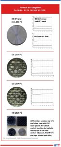
CFC samples were tested in contact with steel samples under laboratory conditions in a vacuum of 7.5 x 10⁻⁷ Torr (1 x 10⁻⁶mbar). Results of the contact with CFC for steel samples at different temperatures are presented to the left (Figure 1). It is important to note that:

  • Sample (0) is the reference sample and had no exposure to the contact test.
  • Sample (0’) is the back side of Sample (0).
  • Sample (1) is the contact side at 1922°F (1050°C).

All three samples are visually identical, therefore only one is shown. Sample (2) at 1967°F (1075°C) and Sample (3) at 2012°F (1100°C) exhibited a distinct visual surface pattern after CFC contact. This was analyzed by Glow Discharge Optical Emission Spectroscopy (GDOES) and the test location (gray spot) clearly observed on Samples (2) and (3). For Sample (4) run at 2057°F (1125°C), the CFC was found to have adhered to the steel surface.

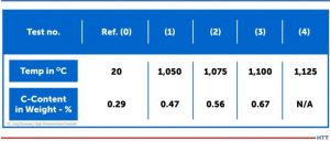
The carbon content in 10mm depth measured with GDOES (see the profiles in Figure 1) increased from initially 0.29 weight-% for the 1922°F (1050°C) test, although nothing was visible on metal surfaces. For carbon contents, see Table 1.

Table 1. Carburizing of 1.6582-samples in 10 µm depth after CX-27C1-contact (GDOES)
Source: Dr. Jorg Demmel, High Temperature Concept

CFC Reactions with Oxygen

The chemical reactions of CFC with various gases are essential in Step 1 (referenced in Part 1 of this article) and an indicator of chemical thermal suitability.

In the case of the unwanted contact carburization considered above is similar, in a sense, to carburization of steel in contact with carbon powder or granulate. However, the actual carburization mechanism, which occurs between approximately 1616°F and 1697°F (880°C and 925°C), does not take place directly via the carbon contact but is based on the fact that solid carbon reacts with atmospheric oxygen according to the Equation Table to form carbon dioxide (CO2).

Equation Table. Reaction rates and activation energies for graphite (800°C; 0.1 bar)
Source: Dr. Jorg Demmel, High Temperature Concept

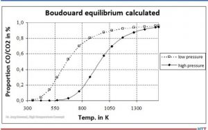
Carbon monoxide (CO) is then formed from CO2 by the Boudouard reaction (Equation 3). At high temperatures and low pressures (see Figure 2), almost only CO is present.

Figure 2. Boudouard equilibrium
Source: Dr. Jorg Demmel, High Temperature Concept

Transport of Carbon

The carbon carrier must be transported to the surface of the parts.

The cases considered in Part 1 of this article were conducted in vacuum, that is in the absence of a carburizing atmosphere. The laboratory tests were even carried out in a vacuum as low as 7.5 x 10⁻⁷ Torr (1 x 10⁻⁶mbar). Nevertheless, part surface reactions were observed.

Transfer Mechanism into the Steel Parts

Theoretically, carbon from the CFC fixtures can be transferred into the steel via solid phase (as opposed to gaseous phase) reactions. Gas particles can be adsorbed by surfaces via physisorption and/or chemisorption. The author’s personal research experience has shown that metal samples usually oxidize after a short time, even in a high vacuum of 7.5 x 10⁻⁷ Torr (1 x 10⁻⁶mbar). In particular, elements such as iron, molybdenum, and chromium have a strong ability to chemically adsorb oxygen or CO.

Furthermore, there is a disproportionately large amount of adsorbed oxygen in the CFC samples. CFC has open porosities as high as 30%. CFC in industrial practice is never completely evacuated. So, there is a disproportionately large amount of oxygen present in CFC fixtures.

It can be assumed that oxygen repeatedly escapes from the CFC and is initially available in the contact area. Proof of this can be provided by the GDOES analysis. Outside the contact areas, no (gas) carburization took place (as evidenced by the non-contact side of steel samples).

The oxygen and carbon surplus combined with close contact lead to complete reaction of oxygen creating carbon dioxide as in Equation (1). Because of the carbon surplus, almost only carbon monoxide is produced as shown in Equation (2). Because of the very close contact between CFC and steel, C-adsorption by gamma iron and desorption of carbon dioxide as in Equation (5) takes place:

Equation 5
Source: Dr. Jorg Demmel, High Temperature Concept

Since carbon dioxide immediately comes in contact with carbon in the CFC again, carbon monoxide is produced according to Equation (3). In other words, carbon dioxide regenerates immediately and the reaction starts again.

Direct carbon transfer from CFC to metal via solid phase is very unlikely since carbon atoms in CFC are firmly bound in rings.

Diffusion of Carbon in the Steel Parts

In solids, the surface diffusion usually takes place at significantly higher diffusion rates than in the bulk material. The thermodynamic driving force of diffusion or carburizing reactions is the difference in carbon activity for a specific concentration in the austenite to that of the reaction medium. The carbon activity is the ratio of the vapor pressure of the carbon in state under consideration to vapor pressure of pure carbon (graphite/CFC). Alloying elements of the steel influence the activity of the carbon.

Part Reactions (Melting and Carbide Formation)

Steel can begin to melt if, at the given values for temperature and pressure, a partially liquid phase is reached, that is, the solidus line in the phase diagram is exceeded. At even higher temperatures, the liquidus temperature can be reached and steel is completely liquid.

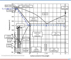
According to metastable iron-carbon diagram phase diagram (Figure 3), a steel such as SAE/ AISI 4340 (34CrNiMo6) alloy (DIN 1.6582) with around 0.47% by weight percent carbon does not begin to melt at 1922°F (1050°C), the exposure temperature for Sample (1), or Sample (2) at 0.56% and 1967°F (1050°C) for Sample (3) with 0.67% for 2012°F (1100°C). The iron-iron carbide phase diagram applies to steels with less than 5% (by mass) of alloying elements and thermodynamic equilibrium, so it is an accurate representation for a SAE/AISI 4340 (34CrNiMo6) alloy.

Figure 3. Metastable equilibrium diagram Fe-Fe3C for steel (good fit for 1.6582)
Source: Dr. Jorg Demmel, High Temperature Concept

A calculation of the solidus temperature shown on the iron-iron carbide diagram (Figure 3), which is dependent on the carbon content and alloying elements, yields a value of 2703.2°F (1,484°C) (J’).

For an SAE/AISI 4340 (34CrNiMo6) steel (DIN 1.6582) with 0.3% C and one for 0.5% C, the calculated solidus temperature is 2640°F (1449°C). This is shown on the J’-E’ blue dotted line in Figure 3. In other words, a lower solidus line (cf. dashed blue line in Figure 3) and thus a slight reduction in austenite phase region.

The iron-carbon diagram also indicates that melting of surfaces that have absorbed carbon (e.g., Sample No. 2) will occur at 1967°F (1075°C). This value is within approximately 90°F (50°C) of the temperature used (dotted line E’-C’-F’). From this information we can conclude that the observations seen in Figure 1 are not the result of melting, but rather imprints due to surface softening.

The melting (c.f., Figure 1) observed in Test No. 4, which occurred at 2057°F (1125°C) is likely due to partial carburization of the steel surface and exceeding the solidus temperature. A micrograph confirms eutectic melting and high carbon content, which could also be indirectly confirmed by hardness measurement.

Carbide Formation

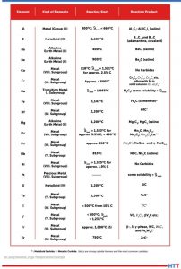
Additional reactions can occur between carbon absorbed from the CFC fixtures and the steel parts due to either separation of carbides (e.g., iron carbide in the form of secondary cementite) or carbide formation with alloying elements such as Ti, V, Mo, W, Cr, or Mn (listed in decreasing tendency to form carbides).

Table 2. Reactions between C and metal
Source: Dr. Jorg Demmel, High Temperature Concept

Table 2 lists various elements in alphabetical order that react with carbon above the specified temperatures to form reaction products mentioned, primarily carbides. It should be noted that the temperatures listed apply only to pure metals and pure carbon. As such, they provide only rough approximations of a temperature at which a reaction might begin.

Countermeasures

There are several measures to avoid these unwanted reactions:

  • Ceramic oxide coatings such as aluminum oxide (Al2O3) or zirconium oxide (ZrO2) layers placed onto the CFC
  • Hybrid CFC fixtures having ceramics in key areas to avoid direct contact with metal workpieces
  • Alumina composite sheets
  • Boron nitride sprays
  • Special fixtures made of oxide ceramics

An yttrium-stabilized zirconium oxide layer (93/7) was applied to CF222 by thermal plasma spray and tested successfully (see Figure 4).

Figure 4. Yttrium-stabilized zirconium oxide layer with an average layer thickness of 110µm on CF222 material. The photograph on the right shows a hybrid CFC fixture.
Source: GTD Technologie Deutschland

Summary

It is important to consider the specific process conditions in advance so that unwanted reactions — from carburization to catastrophic melting of the workpieces — can be avoided. Effective countermeasures can be taken.


References

Atkins, P. W.: Physikalische Chemie. 1. vollst. durechges. u. berichtigter Nachdr.d. 1. Aufl ., Weinheim, VCHVerlag, 1988 – ISBN 3-527-25913-9.

Bürgel, R.: Handbuch Hochtemperatur-Werksto technik: Grundlagen, Werksto bean-spruchungen, Hochtemperaturlegierungen. Braunschweig, Wiesbaden: Vieweg, 1998. ISBN 3-528-03107-7.

Demmel, J.: Advanced CFC-Fixture Applications, their scientific challenges and economic benefits, In: 30th Heat Treating Society Conference & Exposition, Detroit, MI, USA, 15th Oct. 2019.

Demmel, J.: Werkstoffwissenschaftliche Aspekte der Entwicklung neuartiger Werkstückträger für Hochtemperaturprozesse aus Faserverbundkeramik C/C und weiteren Hochtemperaturwerkstoffen, Dissertation, TU Freiberg, Germany, 2003.

Demmel, J.: Why CFC-Fixtures are a Must for Modern Heat Treaters, FNA 2020 Technical Session Processes & Quality, USA, 30th Sept. 2020.

Demmel, J., et al: Applications of CMC-racks for high temperature processes. In: 4th Int. Conf. on High-Temperature Ceramic Matrix Composites, 3.10.2001, p. A-17.

Demmel, J. und J. Esch: Handhabungs-Roboter sorgt für Wettbewerbsvorsprung. Härterei: Symbiose von neuen Werkstoffen und Automatisierung. In: Produktion (1996), No. 16, p. 9.

Demmel, J. und U. Nägele: CFC revolutioniert die Wärmebehandlung. In: 53. Härterei-Kolloquium, Wiesbaden, 10.10.97. Vortrag und Tagungsbericht.

Demmel, J., Lallinger, H.: CFC-Werkstückträger revolutionieren die Wärmebehandlung. In: Härtereitechnische Mitteilungen 54, No. 5, p. 289-294, 1999.

Eckstein, H.-J., et al: Technologie der Wärmebehandlung von Stahl. 2nd Edition, VEB Deutscher Verlag für Grundstoffindustrie, Leipzig, 1987. ISBN 3-342-00220-4.

Godziemba-Maliszewski, J.; Batfalsky, P.: Herstellung von Keramik-Metall-Verbindungen mit Diffusionsschweißverfahren. In: Technische Keramik, Jahrbuch, Essen, 1 (1988), S. 162-172. ISBN 3-80272141-1.

Grosch, J.: Grundlagen-Verfahren-Anwendungen-Eigenschaften einsatzgehärteter Gefüge und Bauteile, ExpertVerlag, 1994, ISBN 3-8169-0739-3.

Hollemann, A.F.; Wiberg, E.: Lehrbuch der anorganischen Chemie / Hollemann-Wiberg. 91.-100. Aufl ., de Druyter Verlag, 1985 – ISBN 3-11-007511-3.

Kriegesmann, J.: Technische Keramische Werkstoffe. Loseblattwerk mit 6 Ergänzungslieferungen pro Jahr.

Kussmaul, K.: Werkstoffkunde II. Stuttgart, Universität, Lehrstuhl für Materialprüfung, Werkstoffkunde und Festigkeitslehre, Vorlesungsmanuskript, 1993.

Lay, L.: Corrosion Resistance of Technical Ceramics. 1. Aufl ., Teddington, Middlesex, Crown-Verlag, 1983 – ISBN 0-11-480051-0.

Marsh, H.; u.a.: Introduction to Carbon Science. 1. Aufl ., London, Butterworths-Verlag, 1989 – ISBN 0-40803837-3.

Spur, G.: Wärmebehandeln. Berlin, 1987, ISBN 3-446-14954-6.

Samsonow, G.V.: Handbook of refractory compounds. New York, 1980.

Schulten, R.: Untersuchungen zum Kohlenstofftransportmit Carbidbildung in Nickelbasis-legierungen. RWTH Aachen, Fakultät für Maschinenbau, Diss., 1988 Deutsche Keramische Gesellschaft, 1990 following. ISBN 3-87156-091-X.


About the Author: Dr. Jorg Demmel is the founder, owner, and president of High Temperature Concept. He received his Engineering Doctorate in the field of CFC workpiece carriers for heat treatment and served in different leading positions for Volkswagen before moving to the U.S. In this article, Demmel draws on his dissertation, “Material scientific aspects of the development of new Fixtures for high temperature processes made of fiber-composite ceramics C/C and other high temperature materials” (Technical University Mining Academy Freiberg, Germany, 2002/3), and his personal experiences. For more information, contact Jorg at jorg.demmel@high-temperature-concept.com


Find heat treating products and services when you search on Heat Treat Buyers Guide.com


CFC Fixture Advantages and Challenges, Part 2 Read More »

Getting to the “Hearth” of It: 5 Hearth Tips

OC

Want a free tip? Read some of the top 101 Heat Treat Tips that heat treating professionals submitted over the last few years. These handy technical words of wisdom will keep your furnaces in optimum operation and keep you in compliance. If you want more, search for "101 heat treat tips" on the website! This selection features 5 tips all about the hearth of your furnace!

Also, check out Heat Treat Resources in the September 2021 magazine to check it out yourself!


Hacksaw Your Hearth!

When loading parts, carefully place the workload on the center of the hearth (front-to-back and side-to-side). Make sure it is stable and no part of the load is close to or touching the heating elements. This can create arcing and damage your parts.

Tip: Once the load is in place, mark the hearth posts with a hacksaw to quickly find the front and back measurements each time.

(Ipsen USA)


TZM Moly Grids

A very commonly observed failure mechanism with a moly post hearth assembly is bending of the moly posts. They will stay fairly straight at the center of the hearth area, but they can distort badly toward the outer sides of the work zone. The outer rows of vertical posts end up leaning away from each other. This is due to the very high linear thermal expansion coefficient of nickel-iron alloy grids (usually 330 SS or Inconel). With a high load on the nickel alloy grid, it is not able to slide on the perpendicular hearth beams as the temperature rises. The outer hearth post rows are forced in an outward direction. The quenching of the furnace load does not reverse all of this effect and over time results in the severe bending of the hearth posts.

Contact us with your Reader Feedback!

By replacing the stainless steel or nickel alloy grids with a moly or TZM alloy moly grid, which exhibits very low thermal expansion, the hearth life can be increased. For comparison, the figure shows the coefficients of linear thermal expansion for commonly used grid materials. For example, a 36” wide 330 SS grid at 70°F grows to 36.6” wide at 2200°F.

Another significant benefit of TZM moly grids is use at higher furnace process temperatures without the problem of a softened, sagging grid that cannot support the load properly.

(Grammer Vacuum Technologies, Inc.)


How to make thru-process temperature monitoring robot friendly!

In modern rotary hearth furnaces, temperature profiling using trailing thermocouples is impossible as the cables would wind up in the furnace transfer mechanism.

Due to the central robot loading and unloading and elimination of charging racks/baskets the use of a conventional thru-process system would also be a challenge.

Faced with such loading restrictions it is necessary to fit the thermal barrier inside the cavity of the product (engine block shown) and allow automated loading of the complete combined monitoring system and product.

To allow miniaturization of the thermal barrier to fit, but also provide sufficient thermal protection, the use of phased evaporation technology is critical. Such a system allowed BSN Thermoprozesstechnik GmbH in Germany to commission such a furnace accurately and efficiently and thereby optimize settings to not only achieve product quality but ensure energy efficient, cost effective production.

(PhoenixTM)


Hearth Height Adjustment

The available width and height of the work zone in a vacuum furnace with a round hot zone is determined by the elevation placement of the top of the furnace hearth. This distance is determined by the length of the vertical hearth support posts. By having spare, interchangeable hearth post sets of varying lengths, one can extend the work zone width or height as needed. The figure shows a variety of work zone dimensions that are possible with a standard 36” wide x 36” tall typical work zone as an example. The important thing in choosing your work zone shape is to maintain an (approximately) 3” clearance between the elements and the work zone to avoid part to element contact.

Note: With the symmetric shapes of modern, round hot zones there is good reason to expect good temperature uniformity anywhere within the 3” clearance ring shown in Figure 1. If you can build a survey fixture capable of surveying all the space you want to use, you theoretically could use more than just the rectangular space shown in the examples. Getting an auditor to accept the survey is a separate task.

(Grammer Vacuum Technologies, Inc.)


TZM Moly Hearths

In the case of furnaces with all-molybdenum hearths or of graphite hearths with molybdenum (“moly”) support posts, a direct replacement of those moly posts with TZM alloy moly posts will both increase strength of the hearth assembly and eliminate problems with recrystallization-induced embrittlement of the posts. (For an all-moly hearth, replacement of the horizontal load beams with TZM would have a similar benefit.) The comparative strengths vs. temperature of TZM alloy and pure moly are shown in the graph. Whereas at room temperature the strengths are very similar (around 110KSI-120KSI), once you exceed the 2000F recrystallization temperature of pure moly, the difference becomes dramatic. At 2000F the pure moly is about 40% of the strength of TZM alloy. By the time it reaches 2300F the pure moly is only about 25% of the strength of TZM alloy.

Not only is the TZM alloy much stronger than pure moly at temperature, but it also does not suffer from the same embrittlement problems. Pure moly, once it has recrystallized, forms very brittle grain boundaries in its microstructure. Its behavior begins to resemble that of glass. This is the primary mode of failure of moly components in vacuum furnaces – breakage due to intermetallic grain boundary embrittlement. TZM’s recrystallization temperature is around 2500F, and even when it does recrystallize, it forms very fine new grains that still have decent ductility. Hence, we recommend TZM alloy as a replacement for pure moly in all structural applications for vacuum furnaces. It is the “right stuff.”

Note that all metals used in a vacuum furnace, moly and TZM alloy included, will suffer from distortion due to the numerous thermal cycles they experience. Moly hearth beams are a good example. Once distorted moly hearth beams can be very difficult if not impossible to straighten without breaking them. To have any chance at all they must be heated to forging temperatures. TZM hearth beams however, due to their good ductility can often be heated to forging temperatures and successfully straightened. Most heat treating shops scrap out the moly hearth beams rather than even trying to straighten and re-use them. With a TZM hearth the hearth components can typically be re-used with a newly re-lined hot zone saving a large additional expense.

(Grammer Vacuum Technologies, Inc.)


Check out these magazines to see where these tips were first featured:


Find heat treating products and services when you search on Heat Treat Buyers Guide.com


Getting to the “Hearth” of It: 5 Hearth Tips Read More »
Weight Loss and Shrinkage: Comparing Furnace Insulation Exposed to Hydrogen Gas

OCWhat material is best suited as thermal insulation, fixtures, and setters in furnaces with hydrogen atmospheres? To find out, ZIRCAR Ceramics, Inc. reports on a series of test results that determine the weight loss and shrinkage of six materials you may use in your heat treat furnace.


Multiple types of fibrous alumina insulation materials were tested to determine their stability in hydrogen gas. Silica bonded types have been known to give superior performance in oxidizing and neutral environments. Alumina bonded types have classically been used as thermal insulation, fixtures and setters in applications where reduction by aggressive furnace atmospheres is encountered. One such aggressive reducing atmosphere is hydrogen, a common cover gas in furnaces for sintering powder metal parts. In hydrogen gas atmospheres, silica -- a common binder which imparts high temperature stability and increased mechanical strength -- is attacked, dissociates and volatilizes resulting in premature failure of the refractory.

Test Method

Cubes of insulation, roughly 1 inch per side, were measured and weighed. They were fired at 1450°C in a model 1725 HTF box furnace manufactured by CM Furnaces, Inc. The furnace was purged with 15 scfh hydrogen gas with a dew point of <40°C. It was heated at a rate of 200°C per hour with soak times of 1, 2, 10 and 50 hours. The samples were removed after each soak, measured and weighed. Weight loss and thickness shrinkage were calculated using experimental data. Shrinkage in the length and width directions were averaged to obtain the data displayed. The materials tested are described in the following table.

Results

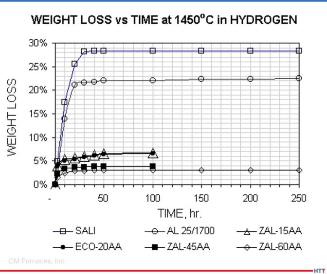
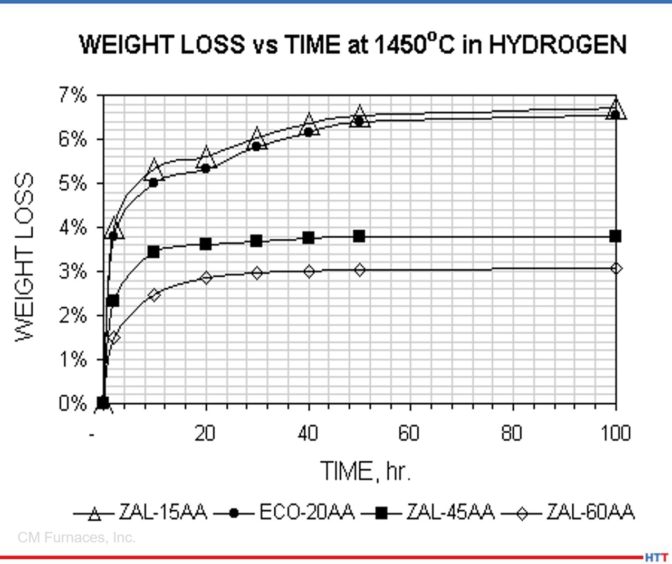
Weight Loss results for all types tested.

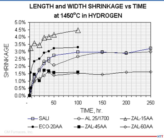
Weight Loss results for alumina bonded types tested. Shrinkage results in length and width directions for all types tested.

Shrinkage results in length and width directions for all types tested.

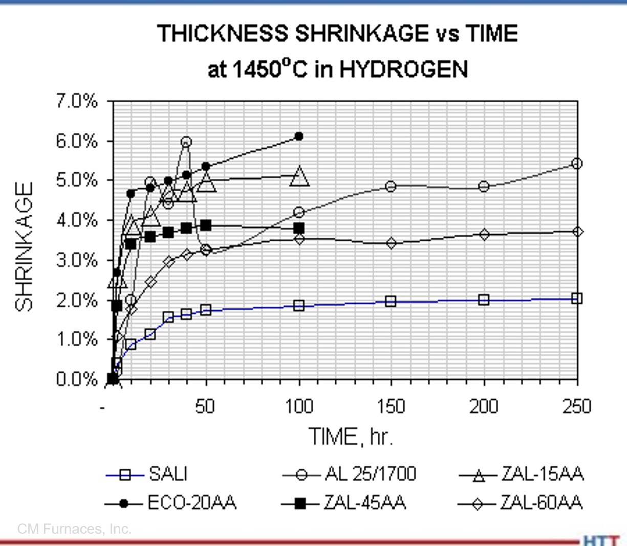
Shrinkage results in thickness directions for all types tested.

Conclusions

Premium (ZAL-45AA) and special (ZAL-60AA) grade fibrous alumina insulation materials appear best suited for use as thermal insulation, fixtures, and setters in furnaces with hydrogen atmospheres as they exhibited the least weight loss and thermal shrinkage of all specimens tested.

Alumina bonded materials (ZAL-15AA, ECO-20AA, ZAL-45AA and ZAL-60AA) showed significantly less weight loss after exposure to hydrogen gas at 1450°C than did the silica bonded types tested.

Silica bonded materials (SALI and AL 25/1700) exhibited significant weight loss after testing at 1450°C in hydrogen.

Thermal shrinkage is inversely proportional to density, independent of the bond type.


Acknowledgements

The data presented in this article was collected by CM Furnaces, Inc. (www.cmfurnaces.com) and provided to ZIRCAR Ceramics, Inc. by Donald T. Whychell Sr., director of Research and Development at CM Furnaces, Inc. (dwhychell@cmfurnaces.com)


.

Search suppliers of ceramic parts and fixtures on Heat Treat Buyers Guide.com


Weight Loss and Shrinkage: Comparing Furnace Insulation Exposed to Hydrogen Gas Read More »

Avoiding Diffusion Bonding of Parts and Fixtures: A Case Study

OCAs most heat treaters know, parts and fixtures often do not mix well. Diffusion bonding can cause the two to fuse together. In this case study, learn how combining thin-film coatings with specific part and fixture design can avoid diffusion bonding. 

Read all about it in today's Technical Tuesday feature, written by Jeff Tomson, sale manager at IonbondThis article was originally published in Heat Treat Today’s December 2021 Medical & Energy print edition.


Jeff Tomson
Sales Manager
Ionbond

A client approached Ionbond looking for a solution to a problem: They had parts diffusion bonding to their fixtures during heat treatment. The client was using 316SS fixture spacers for heat treating 17-4 SS components at 1904°F (1040°C) in a high-vacuum heat treatment furnace and 316L SS components at 1652°F (900°C) in a high-vacuum heat treatment furnace. Due to the chemical affinity of the alloying elements of the two materials, the length of the heat treatment, and the operating temperature, atoms from both materials could intersperse. The resulting diffusion bonding caused difficulty getting the subject parts to separate from the fixtures.

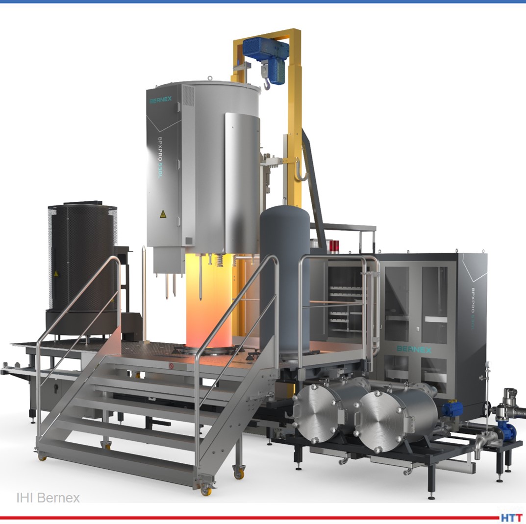
The coating solution needed to be chemically inactive at the processing temperature while providing a defect-free contact surface. Ceramic materials satisfy these requirements; thus, Ionbond's CVD 29 (Al₂O₃) coating was recommended. The CVD process is a method for producing low stress coatings by means of thermally-induced chemical reactions. Typically, the substrate is exposed to one or more precursors such as TiCl₄, CH4, or AlCl₃ which react on the substrate material to produce the desired film. CVD coatings typically do not maintain their characteristics at the elevated temperatures of our client's application for long periods. However, the high-vacuum environment would allow the coating to function above its 1832°F (1000°C) service temperature. The coating has an excellent record in high temperature applications (cutting, forming, etc.) since it is chemically inert and has the ability to maintain a high hardness.

CVD equipment by Bernex

The CVD 29 coating has different variations and many applications. In the cutting tool world, its ability to resist thermal stresses makes it well suited for high-volume machining of mild and stainless steels. In resistance welding it is used heavily for locating pins and splatter guards, as its electrically insulating properties prevent arcing and its high toughness allows for a long life. For high temperature forming, chemical inertness prevents aluminum buildup on die profiles. High wear resistance makes this coating an ideal solution on ferrous and non-ferrous alloys used in hot extrusion and die casting applications. The overall coating thickness varies from 6 to 16 microns, depending on the version being applied as well as the substrate material. The coating produced is multilayered with adhesion-promoting underlayers that are needed to ensure bonding of a ceramic material to steel.

Due to the high coating temperatures, austenitic stainless steel is typically not an ideal substrate for the CVD process due to its low carbon content causing issues with adhesion. It is a better option than martensitic grades as post-coat hardening is unnecessary. Popular substrates for this coating family include carbides, D2, and H13 tool steels. Some exotic materials such as platinum and nickel content alloys are also used for specialized applications in the semiconductor and aerospace industries.

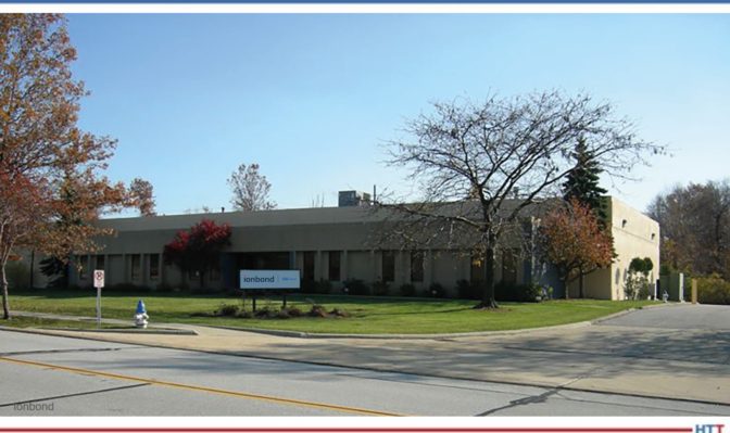
Ionbond's Cleveland team. Ionbond is a global leader in thin-film coatings, which are used to improve durability, quality, functionality, efficiency, and aesthetics of tools and components. Its portfolio includes physical vapor deposition (PVD), plasma assisted chemical vapor deposition (PACVD), chemical vapor deposition (CVD), and chemical vapor aluminizing (CVA) technologies, including a broad range of diamond-like carbon (DLC ) coatings.

Given the nature of the CVD process, typically all surfaces receive uniform coating. In the first trial, the client's spacers were coated utilizing different fixtures to ascertain whether fixturing methods would be a factor. Subsequent client trials revealed no discernable differences.

The first test by the client using the coated parts at 1904°F (1040°C) in a high-vacuum environment was considered a success, with the client stating that the coating performed “excellently.” There was no sign of coating degradation based on the visual appearance and the subject parts were easily removed from the fixtures with no signs of diffusion bonding. The second test was performed at a lower temperature of 1652°F (900°C) and had similar positive results.

Ionbond in Cleveland, OH

Given the success of the first batch, the client ordered another trial. The second set of parts, while made from the same material, were a completely new design. There were three different parts, two that had threads and the third that was a smaller washer shape. Sharp edges can present issues for the CVD process as stresses can build up at the points of the threads and cause the coating to delaminate. The small washers presented their own concerns due to the thin dimensions sparking concerns about excessive movement. Visual inspection after coating showed good adhesion with no delamination, as the threads were not sharp enough to cause issues. The smaller washers also had negligible distortion after coating. The second set of spacers were also tested in heat treatment at 1652°F (900°C) with similar results.

Inspired by these successes, the client is currently having a third set of parts manufactured to further improve the productivity of their fixtures. The geometry of the third set is completely different as our client continues to leverage the performance of the coating with the design for a more efficient fixturing.

About the Author:

Jeff Tomson is the sales manager at Ionbond’s Cleveland, Ohio site. He has been in sales and marketing roles since graduating from the University of Michigan in 1999. He has worked in automotive, aerospace, and thin-film industries.

For more information:

Contact Jeff at Jeff.Tomson@ionbond.com

(216) 704-4395

Avoiding Diffusion Bonding of Parts and Fixtures: A Case Study Read More »
Heat Treating to Take Flight: Titanium Creep Flattening

Source: Aerospace Manufacturing and Design

Heat treating any aerospace projects? Then you know titanium is up there when it comes to VIP alloys in the industry. This best of the web is pulled from an aerospace magazine in which Michael Johnson of Solar Atmospheres answers five questions about creep flattening titanium:

  1. Typical temperatures for creep flattening titanium parts
  2. Whether of not creep flattening can only be done in a vacuum
  3. Best fixturing for creep flattening titanium parts
  4. Can creep flattening minimize movement
  5. Will reheating titanium over 1,000°F affect certification

An excerpt:

"Give your heat treater your material certifications. Many mills will certify to aerospace material specification AMS 2801, AMS 4905, AMS 4911, AMS-H-81200, etc. The material often can be re-annealed while simultaneously creep flattening." - Michael Johnson, Director of Sales, Solar Atmospheres

Read more: "Questions with Michael Johnson"

Heat Treating to Take Flight: Titanium Creep Flattening Read More »

Heat Treating Goes In House

HTD Size-PR LogoThis Heat Treat News piece runs more like a case study, and we want you to see the tasks associated with bringing a heat treat process in house. In this case study, a global manufacturer and supplier of solutions in industrial process instrumentation, KROHNE Group, was outsourcing their large parts to a commercial heat treater in France.

The study details decisions involved in creating a furnace in cooperation with a furnace supplier with locations in Virginia and in the UK as well as shares how a certain particular fixture performed over time and the associated upkeep.


KROHNE Group is a global manufacturer and supplier of solutions in industrial process instrumentation. Within the UK, KROHNE is the group’s global center of excellence for Coriolis mass flowmeter technology. Its manufacturing plant in Wellingborough is where the OPTIMASS range of mass flowmeters is produced.

Their process of manufacturing products often involves working with specialist materials such as Duplex 31803 and Super Duplex 32750 stainless steels. Particularly with regards to materials such as Super Duplex, it is highly critical that the brazing process is completed correctly.

However, KROHNE’s largest products to be brazed are up to two meters in length and no suitable furnace exists within the UK that has the hot zone capability to process such a large product. This meant that the brazing of this product was subcontracted to a supplier in France, which brought challenges with lead times, transport, and associated cost issues.

The objective: bringing the brazing process in-house

Furnace Loaded
Source: Erodex UK

KROHNE’s management team made the decision to bring the process of brazing their larger products in-house, thus ensuring complete control over quality and lead times.

Following a significant investment in the UK’s largest horizontal vacuum furnace, the company required assistance with the design and manufacture of a fixture that would possess the specific hot zone capability, be of appropriate size and at the same time cope with weight, cost and distortion limitations whilst processing the larger products.

Evolution of fixture design

Discussions with Erodex started around six to nine months prior to when the furnace was due to arrive. The original concept design provided by the Erodex UK team was based around using graphite plates and spacers.

Following close consultation with their KROHNE counterparts, this was reviewed and it was determined that a flat grid method would be more suitable, due to strength requirements of the fixture and to enable the required reduction in fixture weight.

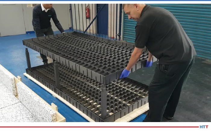
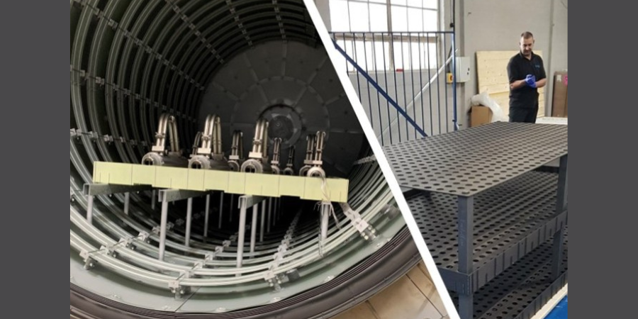
The resulting design was a 2.4m x 1.2m carbon fibre composite (CFC) fixture consisting of 2 layers and a cover plate to ensure that there was no direct radiation heat onto the components processed on the top layer and that heat is evenly distributed within the furnace. Darren Hawes, production engineering manager at the company comments: “We then had a further meeting and added in channels and a cover plate that sits on top of the CFC grid structure to maintain 0.1mm flatness.

“Perforated holes were added to allow the 360-degree gas cooling to flow underneath the fixture to the parts, because cooling is one of the critical features of the process. Side rails were added to the fixture to remove the possibility of any parts falling off and we added lifting points to the fixture, so once removed from the furnace, if the loader were to break down at any point, the fixture could be removed from the loader by overhead cranes”.

Why was Carbon Fiber Composite (CFC) graphite the material of choice for fixture manufacture?

Durability properties such as their high strength, stiffness, high thermal shock resistance and high fracture toughness, combined with being lightweight and having low rates of thermal expansion, CFC is the optimum material solution for charging systems in vacuum furnaces.

Tom Harrison, manufacturing engineer at KROHNE explains why they opted to manufacture the fixture from CFC graphite: “We had to find the right material for the fixture when considering weight, cost and distortion limitations and we could not find another material that was comparable to CFC for achieving this.

“The CFC fixture is lightweight yet as the temperature increases within the furnace the material gets stronger. Our main requirement of the fixture and the plate itself was to have a 0.1mm flatness tolerance, so when we manufacture and process our parts, any distortion of the fixture does not impact on the assembly that is being processed.

“The straight tube assemblies being processed within the furnace also have a 1/600mm straightness tolerance. Up to two metres we can have 3mm distortion end to end in the bow of the tube. To get that right, we required the fixture base to be as true as possible, so that we are not adding any additional distortion into the processing of the parts. The CFC fixture was therefore designed and manufactured by Erodex to deliver on that 0.1mm flatness constraint.

“In addition, the more mass within the furnace, the greater the effect on heating and cooling rates. A metallic fixture can act as a heat sink, using CFC reduces the mass greatly so our process is optimised and the energy we do use is used efficiently.”

Additional benefits of using a CFC grid structure.

An added benefit of a CFC grid structure is that if individual parts of the fixture break, only these need to be replaced. This contrasts with a metallic grid, where the whole grid would need to be replaced or refurbished, resulting in a significant reduction in maintenance costs.

Furthermore, Duplex stainless steel and Super Duplex stainless steel are mainly used for corrosion resistance, meaning that any carbon or other contamination picked up from the fixture itself could affect the metallurgy of the material, which in turn can add further complications to the products being processed.

To avoid this, the CFC graphite fixture was coated in a Yttria Zirconia coating to prevent any carbon ingress into the material. Hawes continues: “As we moved through the process, the design became more complex, so having their expertise at hand to help develop this was very beneficial to us.”

Fixture 3
Source: Erodex UK

Fixture assembly and operation.

Erodex assembled the fixture prior to coating and provided a video demonstrating how this should be repeated. Following coating of the fixture, the team were back on site to reinforce this with demonstrations of the ease of assembly to all KROHNE end users.

Hawes’ team needed to make sure the fixture was precisely central within the furnace every time it is loaded, so the supplier also provided a specialized forklift which utilizes two guides that sit underneath it to centralise the load as it goes in the furnace.

Harrison adds: “The fixture itself has been used now since October, we have completed numerous cycles and it is holding up to design requirements of flatness, the coating is performing well and ultimately, the fixture is achieving what it was required to do… We vacuum clean the fixture and furnace after every cycle to remove any debris coming from the processing. The fixture also goes through a maintenance check/ two weekly burnout to remove any contaminants that may have come onto the fixture because of the processing of the products in the furnace.

“We have also used the CFC graphite fixture to process a product as part of our furnace validation that was previously processed by a subcontractor. We could see that there was 7mm distortion end to end on the part provided by the subcontractor. Once we processed it through on the fixture all the contact points were then level again. We would have not been able to achieve that in a subcontract furnace.

“Ultimately, this has given us full control over processing. It has given us the capability to develop our processes and increase productivity and allows continuous development and improvement of the process too.

“For example, we had identified a few issues with how one cycle was run, where we were positioning the monitoring thermocouples to ensure the parts are fully up to temperature before we started the brazing part of the process, so it has given us further knowledge on that, which in turn has benefitted the product being processed.”


All images provided by Erodex.

Heat Treating Goes In House Read More »

High-Temperature Bearing Failures- Engineering a Solution

Eric Ford, Vice President of Sales and Marketing, Graphite Metallizing Corp.

In this Technical Tuesday original article, read how an automotive manufacturing plant is able to solve high-temperature bearing failures by upgrading to bearings that use a self-lubricating material that can operate in extreme temperatures. Author, Eric Ford, Vice President of Sales and Marketing at Graphite Metallizing Corp., shares how these bearings decreased the need for unplanned and costly maintenance of parts in the case study that follows.


An automotive engine manufacturing plant in the Midwest upgraded the bearings in their gas nitriding ovens after encountering numerous failures with rolling element bearings.

An example of a flame curtain in an industrial setting (Photo source: Graphite Metallizing Corp)

This large manufacturing plant runs automated gas nitriding furnaces for treating their various engine components. A flame curtain, at the entrance to the furnace, produces a vertical stream of combustion products to minimize both the infiltration of room air into the furnace chamber and the disruption of the furnace atmosphere inside. The bearings for the conveyor rollers, closest to the flame curtain, are subjected to intense heat for a short period of time, about 30 seconds, which is enough to cook the grease in the bearings and degrade their performance.

In many automotive plants, these machines are running 24/7 for up to six months at a time. Any breakdown of this equipment has serious consequences in terms of profitability and delivery schedules.

Excessive Downtime

The plant was having trouble with the repeated failure of the rolling element bearings, located just prior to the furnace’s flame curtain. These bearings were failing within six months, causing unscheduled maintenance and downtime. Though there was an automatic grease system, temperatures of approximately 300°F resulted in the grease being cooked away rapidly, resulting in conveyor roller seizure.

When the bearings seized, production on the line stopped. The furnaces then needed time to cool sufficiently for maintenance personnel to be able to access and replace the bearings. Starting the system up again wasted yet more production time.

The conveyor transporting the parts has bearings to support the load and convey the product through the furnace. (photo source: Graphite Metallizing Corp)

It was taking three people about four to six hours to replace the bearings and start the furnace again each time the bearings failed. These unscheduled shutdowns cost tens of thousands of dollars in production loss, labor, and materials. In addition to the expense of the downtime, there was also the added safety risk of handling parts when unloading the furnace and performing maintenance on the equipment, which was still hot.

Successful Trials

At a heat trade show during this time, the production manager of the plant learned about Graphalloy bushing materials; Graphalloy is the name for a specific family of proprietary graphite/metal alloys developed by Graphite Metallizing Corp of Yonkers, NY. Its featured qualities include non-galling, corrosion resistant, dimensionally stable, and can operate at temperatures from cryogenic to higher than 1000°F (538°C). These materials work very well in severe environments and services due to their self-lubricating properties – no grease or oil is required. There are more than 100 grades of these high-temperature bushings which are designed for specific conditions.

Flange Bush 845 (photo source: Graphite Metallizing Corp)

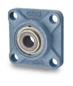
Soon after the show, company representatives went to the plant and proposed a simple drop-in replacement for the current greased bearing flange block assemblies. The production manager agreed to test a few of the company's 4-bolt flange blocks with copper bushings, and they were installed a few weeks later.

The target was a difficult one: The production supervisor said that a doubling of the lifespan of the roller element bearings would enable the plant to stick to its twice-annual scheduled maintenance intervals. By achieving this goal, unscheduled maintenance shutdowns would be avoided.

During the one-year trial period, the high-temperature bushings were a success. Based on the positive result, the production manager installed additional bushing assemblies of this brand type during subsequent scheduled maintenance dates, until all furnaces had been converted to new self-lubricating bushings.

Update: Saving Time and Money

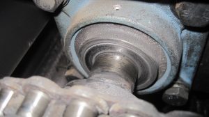
Graphalloy 4-bolt flange block in service. (photo source: Graphite Metallizing Corp)

The original bearing assemblies, installed over six years ago, have been operating  without a single failure or showing any appreciable wear.

By replacing the metal bearings with newer graphite bushings, the automotive company eliminated at least two unscheduled shutdowns and dozens of hours of maintenance work per year. According to the production manager, using this has saved this automotive giant hundreds of thousands of dollars to date.

For more information, Graphite Metallizing Corp

High-Temperature Bearing Failures- Engineering a Solution Read More »
Cleaning Workpieces: Vacuum Vapor Degreasing

Source: VAC AERO International


In order to maintain the cleanliness of workpieces and baskets or fixtures in the vacuum heat treating or brazing process, it is helpful to establish a pre-treating cleaning practice. Vapor degreasing has emerged as a cleaning process with the acting principle that the solvents will dissolve the contaminants on the workpiece and remove them by dripping off the part. In this week’s Technical Tuesday article, a Best of the Web feature, we bring you an article from VAC AERO International addressing the development of the process, the steps involved in vapor degreasing, and comparisons with other cleaning methods.

Cleaning in a solvent offers a level of simplicity and forgiveness not seen in aqueous methods. At one time, solvent cleaning was considered mandatory for successful vacuum processing but environmental concerns (VOC and other emissions) and improvements to aqueous systems including drying technology has seen the industry shift to aqueous cleaning as the norm. Today, however, with the advent of vacuum technology, vacuum vapor degreasing has emerged as a viable alternative to aqueous processing.”

A preview:

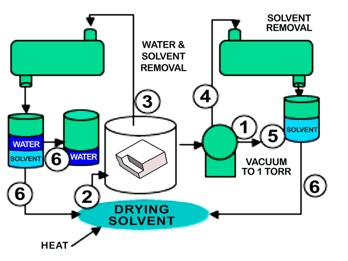
Vacuum vapor degreaser schematic with operational sequence steps. (“Removal of Entrained Moisture from Powdered Metal Parts Using High-Temperature Solvent and Vacuum” PM2TEC 2003, via VAC AERO International)

Main image photo credit/caption: Vacuum Processing Systems LLC (via VAC AERO International) / Typical vacuum vapor degreaser 

Read more: “Vacuum Vapor Degreasing”

Cleaning Workpieces: Vacuum Vapor Degreasing Read More »