AUTOMOTIVE HEAT TREAT TECHNICAL CONTENT

Laser Heat Treating in 3 Automotive Case Studies

Laser heat treating overcomes issues of distortion that are frequent in conventional heat treating methods. Read this Technical Tuesday by Aravind Jonnalagadda (AJ), CTO and co-founder of Synergy Additive Manufacturing LLC, who examines how the automotive industry is achieving desirable dimensional tolerance while avoiding finishing operations like hard milling or grinding.


Technology Overview

Laser heat treatment is a process in which a laser, with a typical spot size from 0.5” x 0.5” to 2” x 2”, illuminates the surface of a metal part to deliver very high energy flux with extreme precision both in time and geometryThis brings the metal’s surface up to the desired temperature very rapidly. Movement of the laser across the surface of the working piece produces hardened tracks.

The phase transformations induced by laser hardening of steels proceed according to the following stages:

  1. Formation of austenite from pearlite-cementite (hypereutectoid steels) or from pearlite-ferrite (hypoeutectoid steels) aggregate structure, during the heating stage.
  2. Martensite transformation from austenite, during the cooling stage.

During this process the short interaction time, in the range of 0.1–0.2 seconds, brings the surface temperature to 1337°F –2732°F (725°C –1500°C). Under these conditions, the original pearlite colonies transform into high-carbon metastable martensite due to self-quenching. This martensite phase increases the hardness.

Key Benefits of Laser Heat Treating

Consistent Hardness Depth: Laser heat treatment delivers consistent hardness and depth by precisely applying high energy to the metal. Millisecond-speed feedback control of temperature ensures specifications are met, as shown in the metallographic cross-section view of laser heat treated D6510 cast iron (Figure 3).

Minimal to Zero Distortion: The high energy density of laser heat treatment minimizes distortion, benefiting components like large automotive dies, gears, bearings, and shafts.

Precise Application of Beam Energy: The laser spot precisely heats the intended area, avoiding unnecessary heating of surrounding areas. This is particularly advantageous for surface wear applications, allowing for surface hardening while maintaining the rest of the material in a medium-hard or soft state, thus combining hardness and ductility.

No Hard Milling or Grinding Required: Laser heat treatment’s low-to-zero distortion reduces or eliminates the need for hard milling or grinding. Post-treatment material removal is minimal and can be managed with polishing. This reduction in finishing operations can save up to 20% in overall manufacturing costs.

Laser Heat Treatable Materials

Any steel with ≥ 0.2% carbon content is treatable by laser heat treatment. In real-world applications, the areas of dies that have been treated with laser heat treatment are generally as hard as, or harder than, the same areas of identical dies treated by conventional hardening treatment.

Common heat treatable automotive materials are indicated in Table 1. This is not a comprehensive list.

Table 1. Common heat treatable automotive materials and the percentage of their metallurgical composition

Cost Savings

In automotive tooling, the conventional practice is to mill the dies in soft state, intentionally leaving an extra 0.015” to 0.020” of material on the surfaces. This excess material acts as a buffer to accommodate distortions from subsequent heat treatments like flame or induction processes. After this initial phase, the dies undergo heat treatment and are then hard milled to achieve the specified tolerances before assembly.

Figure 1. Conventional die construction process vs. the process that utilizes laser heat treating

An alternative method gaining traction, however, is laser heat treating (Figure 1). In this approach, the dies are machined to final tolerance from the beginning and then laser heat treated without causing distortions. This eliminates the need for a secondary hard milling operation. Automotive tool and die clients have reported cost savings exceeding 20% due to this streamlined process.

New Advancements

A Promising Application: Hardening Sharp Edges on Trim Dies

Figure 2. Trim die being laser heat treated using Synergy’s Multi-Point Temperature Control System

 Within the automotive industry, trim dies hold a pivotal role in shaping sheet metal stampings (Figure 2). These dies are instrumental in cutting the metal sheets after forming operations. Typically, a trim die comprises numerous smaller steels assembled onto a die shoe. Ensuring the durability and hardness of these trim dies is imperative, as they must withstand considerable shear and fatigue loads.

Traditionally, heat treatment methods like flame or induction have been employed for treating trim inserts. However, these conventional techniques come with inherent drawbacks. Issues such as rolled edges and high heat input often lead to significant distortion in the dies. To compensate for this distortion, die makers commonly leave approximately 0.020” of stock material, which then requires hard milling to meet specifications. This process consumes substantial time and resources.

To address these challenges effectively, many die makers have recently turned towards laser heat treating for their trim inserts.

Multi-Point Temperature Control System (MPTC)

Figure 3. Cross-section of test sample demonstrating laser heat treated trim edge and the hardness of the cutting edge

Another innovation has been the use of more advanced temperature control units. The need to overcome temperature control challenges led to the development of the Multi-Point Temperature Control System (MPTC). This system enables Synergy to regulate laser power and temperature distribution over the entire cutting edge, ensuring consistent and controlled heat treatment without melting the cutting edge.

Case Study: Press Brake Tooling Hardening

High precision press brake tools are essential for the metalworking industry, providing the necessary precision and durability for bending and shaping sheet metal. These tools are crafted from a variety of materials, including 4140, S7, A2, and D2 steels, each known for their unique properties and performance characteristics. However, hardening these tools presents significant challenges due to their lack of mass, which often leads to serious distortion, especially in longer pieces.

Figure 4. 10 ft-long laser hardened and polished press brake tooling (material 4140 alloy steel, typical hardness achieved: 55–60 HRC)

Traditional hardening methods can cause substantial distortion in press brake tooling. This is particularly problematic for long tools, where uneven heating and cooling can lead to warping. The need for precise dimensions and smooth operation in press brake tooling makes any level of distortion unacceptable, as it can affect the accuracy and quality of the final product.

Laser hardening of press brake tooling at Synergy has demonstrated remarkable results. For tools less than 10 inches in length, the recorded distortion is less than 0.001 inches. Even for longer tools, measuring up to 10 feet, the overall distortion was maintained at less than 0.050 inches.

Case Study: Hem Die Laser Heat Treatment

Hemming is a critical operation in the production process and has a significant impact on the overall quality and performance of a vehicle. Hemming involves bending the edge of a sheet metal over itself, and it is performed on various components such as hoods, doors, tailgates, and fenders. Hemming dies, also known as anvils, play a crucial role in this process and are compact compared to conventional stamping dies, but this presents a new set of challenges for die makers.
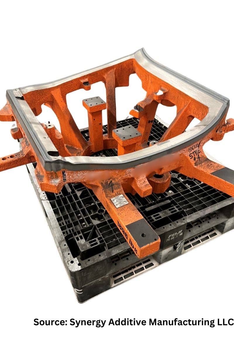
Figure 5. Hem die laser hardening on the perimeter edge (material D6510 cast iron, typical hardness 58-62 HRC)

Conventional heat treating methods, such as induction and flame hardening, can cause substantial distortion in hemming dies and result in inconsistent hardness across the profile. Additionally, the dies require a great deal of post-machining to bring them back to the desired tolerance. This not only results in substantial cost but also adds time to the production process, leading to increased time to market (TTM).

Laser heat treating offers a solution to these challenges and helps to maintain the quality of hemming dies. With Synergy’s laser heat treating process, the die is laser heat treated after it is machined to its final dimensions, resulting in minimal to no distortion and consistent hardness. This eliminates the need for additional hard milling processes and helps to reduce the TTM. Extensive testing by Synergy’s clients has shown that laser heat treated anvils exhibit consistent hardness within ±1 HRC and do not require additional hard milling operations.

Case Study: Punch Pins Laser Hardening
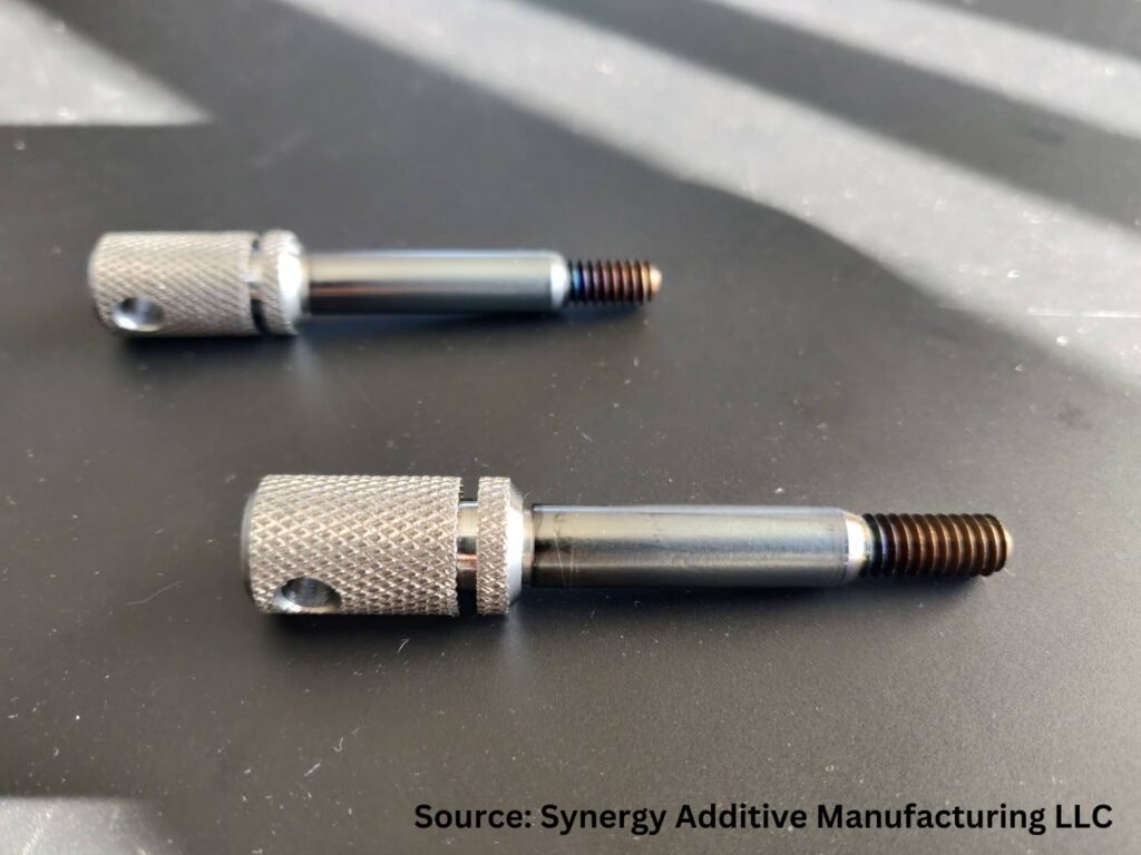
Figure 6. Laser heat treat punch pins (Diameter 0.375”, length 2.5”, material 4140 alloy steel)

Uniform laser heat treating of punch pins with distortion of less than 0.0005” can be achieved with laser heat treating on pins and other cylindrical components. A demonstration of this application on a 4140 alloy steel part is depicted in the Figure 6. Laser hardening resulted in a surface hardness of 60 HRC with a case depth of 0.010”.

Conclusion

The automotive industry increasingly requires precise, repeatable methods to not only meet standards but also remove steps for manufacturers creating these components. As the three case studies demonstrate, laser heat treating is a key tool that heat treaters should use to improve energy efficiency, avoid distortion, and increase overall quality.

References

Asnafi, Nader, Tuve Johansson, Marc Miralles, and Andreas Ullman. “Laser Surface-Hardening of Dies for Cutting, Blanking or Trimming of Uncoated DP600.” Recent Advances in Manufacture & Use of Tools & Dies and Stamping of Steel Sheets, Olofström, Sweden (October 5-6, 2004).

Beyer, E., F. Dausinger, A. Ostendorf, A. Otto. “State of the Art of Laser Hardening and Cladding.” Proceedings of the third International WLT-conference on Lasers in Manufacturing, (2005): 281–305.

Pashby, I.R., S. Barnes, and B. G. Bryden. “Surface hardening of steel using a high power diode laser.” Journal of Materials Processing Technology, University of Nottingham, Nottingham, UK b Warwick Manufacturing Group, University of Warwick, Warwick, UK,139, (2003): 585–588.

Jonnalagadda, Aravind and Brian Timmer. Great Designs in Steel Presentations: Laser Heat Treating of Automotive Dies for Improved Quality and Productivity. Michigan, 2021. https://www.steel.org/wp-content/uploads/2021/06/GDIS-2021_Track-3_08_-Jonnalagadda.Timmer_Laser-Heat-Treatment-of-Auto-Dies.pdf.

Selvan, J. Senthil, K. Subramanian, and A. K. Nath. “Effect of laser surface hardening on En18 (AISI 5135) steel.” Journal of Materials Processing Technology 91, 1–3 (June 1999): 29–36.

About the Author:

Aravind Jonnalagadda
CTO and Co-Founder
Synergy Additive Manufacturing LLC
Source: LinkedIn

Aravind Jonnalagadda (AJ) has over 20 years of expertise in laser material processing. Synergy provides high power laser-based solutions for complex manufacturing challenges related to wear, corrosion, and tool life specializing in laser systems and job shop services for laser heat treating, metal based additive manufacturing, and laser welding.


For more information: Contact AJ at aravind@synergyadditive.com or synergyadditive.com/laser-heat-treating/.


Find Heat Treating Products And Services When You Search On Heat Treat Buyers Guide.Com

Laser Heat Treating in 3 Automotive Case Studies Read More »
Fueling Efficiency: Retrofit Heat Treat Furnace with Combustible Burner Technology

The automotive industry is going electric — electric vehicles are a popular choice for consumers. To continue sustainable efforts for a healthier planet, heat treaters need to seriously consider energy recovery technologies for their equipment and processes. In this Technical Tuesday article, Harb Nayar, founder, president, and CEO at TAT Technologies, examines the use of combustible burner technology (CBT), specifically CBT technology retrofitted on conveyor furnaces that utilize some level of combustible produced by synthetic or generated atmospheres, and that have peak temperatures above 1400ºF (760ºC).


Annealing, brazing, and even powder metal (PM) sintering, metal injection molding, and additive manufacturing offer the automotive industry components with the precision to meet their demanding standards. For example, the nature of PM manufacturing produces minimal waste, both from a material and an environmental perspective. But most in-house and commercial heat treaters fail to capture and reuse energy or convert emissions with environmentally unfriendly pollutants by use of efficient and available gas-neutralizing equipment. These devices capture and thermally combust hydrocarbons, carbon monoxide, and noxious gases such as ammonia.

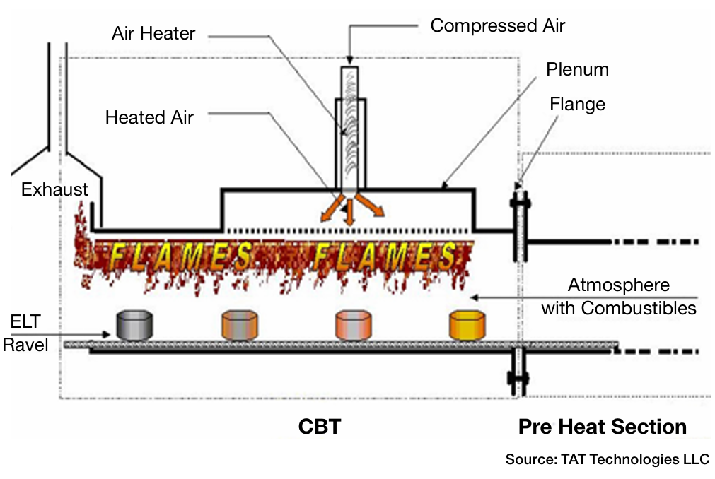
Figure 1. CBT unit (model based on LBT-I unit)

The reality is that rather than just neutralize these emissions, heat treaters can use them to heat their parts, even before preheating. The focus of this article is to examine the use of combustible burner technology (CBT) and more specifically, CBT technology retrofitted on conveyor furnaces for processes that has the following:

  • Have peak temperature above 1400ºF (760ºC).
  • Utilize some level of combustible (e.g., H2, CO, and CH4) produced by synthetic atmospheres (e.g., N2-H2) or generated atmospheres (e.g., Exothermic, Endothermic and dissociated ammonia).
Here’s a 20-second video of “dancing” flames exiting a conveyor furnace that is sintering PM parts in a N2-H2 atmosphere at 2050°F (1,000+ lb./hr.). Source: TAT Technologies

Recovering Latent Heat Energy

A typical conveyor furnace found on the shop floor has three distinct zones, a preheat zone, a high heat zone, and a cooling zone. Since it is desirable in these units to have a forward atmosphere flow (toward the entrance end of the furnace and opposite the direction of part travel), combustibles emitted while processing the parts exit at the entrance and are typically burned off before entering the room or exhaust system. Often, flames can be seen burning at the front of the furnace. 

Combustible burner technology, aka lubricant burner technology (LBT), is a thermal technology that was originally developed to address issues in the PM industry (Figure 2). This technology can be supplied with or retrofitted on the front of a conveyor furnace to recover latent combustion energy from combustibles (e.g., H2, CO, CH4) or hydrocarbon vapors (e.g., wax lubricants used for PM parts). The energy can be reused to heat parts before entering the preheat zone. This means that the preheat zone itself can be significantly shortened.  

Retrofit Example — PM Sintering Furnace

PM processing is very specific and often more difficult to adopt compared to other continuous atmosphere furnaces. Given the large percentage of PM parts used by the automotive industry, it offers a good example of how heat treaters can achieve energy and cost savings via energy recovery technology.

A Close Look at the Process

Sintering is commonly performed in continuous atmosphere furnaces. In the sintering process, powder metal is combined with a binder, often solid wax (Acrawax®) or stearate-based lubricants are used in the compaction process to make green parts. Delubrication (aka delube, debindering) then takes place in the preheat section of the furnace. There are three phases during PM sintering:

Typical door-to-door time varies between one to five hours, depending upon the material being sintered.

The most common atmosphere used in sintering processes is N2 with 7–20% H2. In other shops, the atmosphere used is Endothermic gas, which has (approximately) 40% H2, 20% CO, with the balance primarily N2 or dissociated ammonia (DA) with a composition of 75% H2 and 25% N2. In some sintering operations, a mixture of DA and N2 is used.

The atmosphere with all the combustibles travels from the high heat section to the preheat section and finally exits from the front of the furnace where the various pollutants are burned off before entering the exhaust system. The total amount of combustibles varies between 10% and 50% depending on the type of atmosphere and material being sintered.

For example, CBT units have been installed for the delubing of tungsten-based alloy parts prior to sintering in high temperature pusher furnaces.

Capturing Latent Energies

During the PM sintering process, users can capture this latent heat to transfer this energy into the green parts prior to the preheat section. The following are approximations of the latent combustion energy available:

  • H2: approximately 0.1 KW per cubic foot of H2 or 0.35 KW per cubic meter of H2
  • CO: approximately 0.12 KW per cubic foot of CO or 0.4 KW per cubic meter of CO
  • Wax lubricant: approximately 5 KW per lb. or 11 KW per kg of lubricant going into the furnace

How CBT Works

The CBT unit retrofits to the flange of the preheat muffle of the sintering furnace. In its reaction chamber, the furnace atmosphere gases enter from the heating sections carrying the various combustibles. These are circulated in the chamber in which preheated air at 1000–1600°F is introduced through vents in the roof of the chamber (Figure 1).

When the furnace atmosphere and air mix, a combustion reaction takes place with flames being produced over the incoming load of parts that are traveling on the belt towards the preheat section. Heat from theses flames helps vaporize the lubricant and any oils present at a high rate. The lubricant vapors flowing out of the parts are instantly and continuously consumed within the CBT chamber before leaving to enter the exhaust system in the front of the furnace. However, the energy released from the burning lubricants and oil vapors remains, adding to the energy from combustion within the CBT chamber. Enough total heat is generated to heat the parts and the belt to temperature above 930ºF (500ºC) before entering the preheat section. This “recovered” heat energy is essentially free as it is generated from the combustibles and lubricant and oils (e.g., H2 for oxide reduction and lubricant for ease of compaction).

Figure 4. Illustration of the energy generated within the CBT reaction chamber. Parts are moving from right to left. Source: TAT Technologies

Another Case Study Illustration

Energy recovery in a CBT reaction chamber from fully combusting H2 coming from the preheat section of the furnace at a flowrate of 400 CFH (11.3 m3/h) and lubricant coming with the green parts at a rate of 7.2 lbs (3.3 kg) per hour is approximately 235,000 Btu/hr (248 MJ/hr) which is equivalent to an energy savings of approximately 70 KWh of electricity.

Additional Heat Treat Applications

Many other heat treating processes benefit from CBT technology. Some examples follow next.

Annealing often utilizes continuous furnaces.

  • The percentage of H2 in the atmosphere is generally much higher — in some cases 100%.
  • Materials and annealing practices vary from plant to plant.
  • Prior to annealing, the material often has surface oxidation and/or some type of coating (e.g., oils, dry lubricants).
  • The goal is to avoid decarburization and produce an acceptable microstructure, which highly depends on the time/temperature cycle.

Brazing is another thermal process that benefits from CBT technology. 

  • Brazing of most automotive parts is done in either in Exothermic or Endothermic gas or N2-H2 or H2-Ar atmospheres.
  • Materials being brazed are typically low carbon steels or stainless steels. In some instances, other special materials are used.
  • The goal is to have clean, oxide, and soot-free joint surfaces just before the filler metal (commonly copper or nickel-based alloys) melts, flows into the gap between the parts by capillary action, and solidifies producing a homogeneous part.

Summary

Figure 5. Photo shows the main body of a CBT unit. Different product models vary in length and flow capacity, but all produce improvements in product throughput up to 25–50%. Source: TAT Technologies

Heat recovery units like CBT are essential for not only neutralizing harmful furnace gases but oils or other types of organic compounds. This technology allows latent heat energy to be utilized, increasing efficiency and saving energy. Benefits include:

  1. Emission control. Using combustion technology, heat treaters are able to convert potentially harmful pollutants from reaching the exhaust system.
  2. Increased productivity. The technology increases throughput up to 50% depending upon the model used since incoming parts are heated prior to entering the preheat section of the furnace.
  3. Energy savings. The power requirements in the preheat section are reduced and throughput increases up to 50% depending upon the model used.
  4. Improved heat transfer. Parts can be heated to a higher temperature in a shorter amount of time for faster removal of organic materials prior to subsequent reduction of metal oxides.
  5. Decreased unit cost. The energy consumption is lowered and overall cost of parts produced in reduced.
  6. Environmental benefits. Ambient temperature in the front-loading area by 10–30°F is lowered since the burn off flames are significantly smaller. Processes being run are less sensitive to air infiltration in the vicinity of the furnaces.

About the Author:

Herb Nayar
President & CEO
TAT Technologies
Source: TAT Technologies


Harb is an inquisitive learner and dynamic entrepreneur who will share his current interests in the powder metal industry, and what he anticipates for the future of the industry, especially where it bisects with heat treating.


For more information: Contact Harb at harb.nayar@tat-tech.com.


Find Heat Treating Products And Services When You Search On Heat Treat Buyers Guide.Com


Fueling Efficiency: Retrofit Heat Treat Furnace with Combustible Burner Technology Read More »

Thermal Processing for EV Components

The advent and increasing adoption of electric vehicles (EVs) has brought a wave of change to the automotive supply chain, including the heat treating industry. While the internal combustion engine (ICE) and all its related components may one day become a thing of the past, there are several key areas of every vehicle that aren’t going anywhere fast. In this Technical Tuesday article, Rob Simons, metallurgical engineering manager at Paulo, discusses the difference between EV and ICE vehicles and the latest heat treating trends to be aware of.


ICE vs. EV Technology

The most apparent difference between EVs and ICE vehicles is that, with EVs, fuel and internal combustion engines are no longer needed. The two vehicle types rely on different sets of key components, and when it comes to making the cars run, EVs use fewer parts that require heat treatment.

Table 1. Existing ICE technology vs. EV technology

Without ICE systems, EVs require fewer fasteners, shafts, gears, and rods — all parts that are typically heat treated. But that doesn’t mean heat treatment is less critical for EVs. In fact, certain parts require additional attention on EVs when compared to ICE vehicles, and many safety-critical parts remain the same across both categories. Let’s begin our discussion with the differences in braking systems between the two technologies and what that means for heat treatment.

Latest Trends in Disc Brake Rotors

How EV Brake Systems Work

There’s no question that electric power innovations have completely revolutionized the way vehicles (and the automotive industry) operate. The regenerative braking system is just one aspect of this. Instead of relying on the conventional hydraulic system every time you press the brakes (which uses friction to decelerate), manufacturers have found a way to use the vehicle’s kinetic energy to put the electric motor into reverse, slowing down the vehicle and returning energy to the battery.

Although regenerative braking is more efficient, hydraulic braking still has one key advantage: stopping power. EVs today are equipped with conventional braking mechanisms for emergency purposes.

The Rust Conundrum

To address recurring rotor corrosion, heat treaters introduced ferritic nitrocarburizing (FNC). FNC is a thermal process traditionally used for case hardening, and for brake rotors, it’s used to achieve corrosion resistance.

The Solution: Corrosion-Resistant Rotors with FNC

To address recurring rotor corrosion, heat treaters introduced ferritic nitrocarburizing (FNC). FNC is a thermal process traditionally used for case hardening, and for brake rotors, it’s used to achieve corrosion resistance.

Figure 1 shows a perfect example of the difference that FNC makes. These are pictures of brake rotors from electric vehicles owned by two Paulo team members — one has brake rotors that were ferritic nitrocarburized and show no signs of rust, whereas the other did not go through the FNC process.

Ferritic Nitrocarbonizing Process

FNC is a case hardening technique that uses heat, nitrogen, and carbon to toughen up the exterior of a steel part, improving its durability, decreasing the potential for corrosion, and enhancing its appearance. FNC is unique in that it offers case hardening without the need to heat metal parts into a phase change (it’s done between 975–1125°F). Within that temperature range, nitrogen atoms can diffuse into the steel, but the risk of distortion is decreased. Due to their shape and size, carbon atoms cannot diffuse into the part in this low-temperature process. However, carbon is necessary in the FNC process to generate desirable properties in the intermetallic layer.

Heat Treated Materials for Automotive Seating Components

Safety-Critical Components

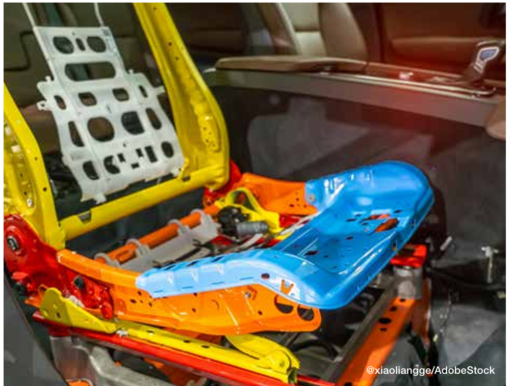
Like brake rotors, many automotive seating components (like mechanisms for seat recliners) are here to stay. Thermal processing is used to achieve stringent specifications that are put in place to keep drivers safe in the event of a collision. EV seat components and the thermal processes used to make them crash-ready are identical to those of ICE vehicle components.

Figure 2. To achieve the stringent specifications for components like seat recliners, identical thermal processing is implemented for both EVs and ICE vehicles.

Seating Components

Generally, these components are case hardened (either carburized or carbonitrided), typically using one of the following materials:

  • 1010 and 1020 carbon steel: These are plain carbon steel with 0.10% carbon content, fairly good formability, and relatively low strength.
  • 1018 carbon steel: 1018 is a grade that’s often chosen for parts that require greater core hardness and better heat treatment response than 1010 or 1020.
  • 10B21 boron steel: Boron steels are becoming more popular in the automotive industry due to their excellent heat treatment response.
  • 4130 alloy steel and 8620 alloy steel: Alloy steels are more responsive to heat treatment than plain carbon steels, so the thermal processing specifications for parts made from these materials are often adjusted to account for the material’s innate strength properties.

Seat Belt Latches

High-strength seat belt latches are usually made from the following materials:

  • 4140 and 4130 alloy steels: 4140 alloy steel is one of the most common engineering steels used in manufacturing. For seat latches and hooks, 4140 and 4130 will be neutral hardened to increase their strength and hardness throughout due to the high performance and precision required of these parts.
  • 1050 carbon steel: 1050 is a medium carbon steel that contains 0.47–0.55% carbon content. Carbon steels are a less expensive choice when compared to alloy steels such as 4140 or 4130.

Seat Frames and Brackets

Seat frames (also known as seat brackets) give car seats their shape using slender pieces of steel joined together to form the skeleton of the seat. These components are often made from boron steels:

  • 10B21 or 15B24 boron steel: These are a good choice for seat brackets because they are only marginally more expensive than other steels used in seating but have impressive toughness, have a good heat treat response, and are weldable.

A Closer Look: Case Hardening for Seating Components

Case hardening diffuses carbon or carbon and nitrogen into the surface of a metal from the atmosphere within a furnace at high temperatures. Adding carbon or carbon and nitrogen to the surface of steel hardens a metal object’s surface while allowing the metal deeper underneath to remain softer, creating a part that is hard and wear-resistant on the surface while retaining a degree of flexibility with a softer, more ductile core. This softness and ductility create toughness in parts, allowing them to respond to stress without failing. Case hardening is a general term for this heat treating method. Depending on the materials and specifications for the part, we apply various case hardening techniques, including carburizing and carbonitriding.

Figure 3. When it comes to heat treating, innovations are rarely exclusive to EVs.

Carbonitriding

During carbonitriding, parts are heated in a sealed chamber well into the austenitic range — around 1600°F — before nitrogen and carbon are added. Because the part is heated into the austenitic range, a phase change occurs, and carbon and nitrogen atoms can diffuse into the part. Carbonitriding is used to harden surfaces of parts made of relatively inexpensive and easily machined or formed steels, which we often see in automotive metal stampings. This process increases wear resistance, surface hardness, and fatigue strength. It is also good for parts that require retention of hardness at elevated temperatures.

Neutral Hardening

Also called through hardening, neutral hardening is a very old method for hardening steel. It involves heating the metal to a specified temperature and then quenching it, usually in oil, to achieve high hardness/strength. In this process, the primary concern is increasing hardness throughout the part, as opposed to generating specific properties between the surface and the core of the part.

All of the metal components of a seat belt, including seat belt loops, tongues, and buckles, are neutral hardened. Specifications typically dictate that these components are hardened to up to 200 thousand pounds per square inch (ksi).

Because seat belt components are visible to the end consumer, their cosmetics are important in addition to their mechanical properties. It’s important to keep the furnace free of soot and thoroughly clean the parts both before and after heat treatment. Proper cleaning readies the part for secondary processing, ensuring the success of activities like polishing and chrome plating.

The Convergence of EV and ICE Vehicles

To learn more about automotive heat treating, download the free Paulo Heat Treat Guide at paulo.com/AutoGuide.

The EV revolution has significantly transformed automotive manufacturing. Despite these changes, EV parts remain remarkably similar to those of their internal combustion engine (ICE) counterparts. Consequently, any advancements in materials or heat treating processes are swiftly adopted across the entire automotive sector. When it comes to heat treating, innovations are rarely exclusive to EVs.

About the Author:

Rob Simons
Metallurgical Engineering Manager
Paulo

Rob provides internal and external customer support on process design, material behavior, job development, reduction of variation, and physical analyses at Paulo. He holds a Bachelor of Science in Metallurgical Engineering from the Missouri University of Science & Technology (formerly known as the University of Mines and Metallurgy) and has worked at Paulo since 1987. Rob has analyzed several million hardness data points and/or process behaviors, leading him to develop many process innovations in the metallurgical field.


For more information: Contact Rob at rsimons@paulo.com.


Find Heat Treating Products And Services When You Search On Heat Treat Buyers Guide.Com


Thermal Processing for EV Components Read More »
Overcoming Quality Challenges for Automotive T6 Heat Treating

Three elements in the T6 aluminum heat treatment process — high temperature solution heat treatment, drastic temperature change in the water quench, and a long age hardening process — challenge accurate temperature monitoring. Thru-process technology gives in-house heat treaters the power to control these variables to overcome the unknowns. In the following Technical Tuesday article, Dr. Steve Offley, “Dr. O”, product marketing manager at PhoenixTM, examines the path forward through the challenges of aluminum heat treating.


Aluminum Processing Growth

In today’s automotive and general manufacturing markets, aluminum is increasingly becoming the material of choice, being lighter, safer, and more sustainable. Manufacturers looking to replace existing materials with aluminum are needing new methodology to prove that thermal processing of aluminum parts and products is done to specification, efficiently and economically.

To add strength to pure aluminum, alloys are developed by the addition of elements dissolved into solid solutions employing the T6 heat treatment process (Figure 1). The alloy atoms create obstacles to dislocate movement of aluminum atoms through the aluminum matrix. This gives more structural integrity and strength.

FIgure 1. Critical temperature phase transitions of the T6 aluminum heat treatment process
Source: PhoenixTM

Process temperature control and uniformity is critical to the success of T6 heat treat to maximize the solubility of hardening solutes such as copper, magnesium, silicon, and zinc without exceeding the eutectic melting temperature. With a temperature difference of typically 9–15°F, knowing the accurate temperature of the product is essential. Control of the later quench process (Figure 1, Phase 3) is also critical not only to facilitate the alloy element precipitation phase but also to prevent unwanted part distortion/warping and risk of quench cracking.

T6 Process Monitoring Challenges

The T6 solution reheat process comes with many technical challenges where temperature profiling is concerned. The need to monitor all three of the equally important phases — solution treatment, quench, and the age hardening process — makes the trailing thermocouple methodology impossible.

Figure 2. Thru-process temperature monitoring of the three T6 heat treatment phases
Source: PhoenixTM

Even when considering applying thru-process temperature profiling technology, sending the data logger through the process, protected in a thermal barrier (Figure 2), the T6 heat treat process comes with significant challenges. A system will not only need to protect against heat (up to 1020°F) over a long process duration but also withstand the rigors of being plunged into a water quench. Rapid temperature transitions create elevated risk of distortion and warping which need to be addressed to give a reliable and robust monitoring solution.

Certain monitoring systems can provide protection to the data logger at 1022°F for up to 20 hours (Figure 3).

Figure 3. Thru-process temperature profiling system installed in the product cage monitoring the T6 heat treatment (solution treatment, quench, and age hardening) of aluminum engine blocks

Thermal Protection Technology

To meet the challenges of the T6 heat treat process, the conventional thermal barrier design employing microporous insulation is replaced with a water tank design, with thermal protection using an evaporative phase change temperature control principle. Evaporative technology uses boiling water to keep the high temperature data logger (maximum operating temperature of 230°F) at a stable operating temperature of 212°F as the water changes phase from liquid to steam. The advantage of evaporative technology is that a physically smaller barrier is often possible. It is estimated that with a like for like size (volume) and weight, an evaporative barrier will provide in the region of twice the thermal protection of a standard thermal barrier with microporous insulation and heat sink. The level of thermal protection can be adjusted by changing the capacity of the water tank and the volume of water. Increasing the volume of water increases the duration at which the T6 temperature barrier will maintain the data logger temperature of 212°F before it is depleted by evaporation losses.

The TS06 thermal barrier design (Figure 4) incorporates a further level of protection with an outer layer of insulation blanket contained within a structural outer metal cage. The key role of this material is to act as an insulative layer around the water tank to reduce the risk of structural distortion from rapid temperature changes both positive and negative in the T6 process.

Figure 4. TS06 thermal barrier design showing water tank, housing the data logger at its core, installed within structural frame containing the insulation blanket surface layer; water tank shown with traditional compression fitting face plate seal
Source: PhoenixTM

Obviously, the evaporative loss rate of water is governed by the water tank geometry. A cube shaped tank will provide the best performance, but this may need to be adapted to meet process height restrictions. A TS06 thermal barrier with dimensions 8.5 x 18.6 x 25.2 inches (H x W x L) offering a water capacity of 3.5 US gallons provides 11 hours of protection at 1022°F. A larger TS06 with approximately twice the capacity 12.2 x 18.6 x 25.2 inches (H x W x L) and 7.7 US gallons gives approximately twice the protection (20 hours at 1022°F).

Innovative IP67 Sealing Design

Passing through the water quench, the data logger needs to be protected from water damage. This is achieved in the system design by combining a fully IP67 sealed data logger case and water tank front face plate through which the thermocouples exit. Traditionally in heat treatment applications, mineral insulated thermocouples are sealed using robust metal compression fittings. Although reliable, the compression seals are difficult to use, requiring long set-up times. The whole uncoiled straight cable length must be passed through the tight fitting which, for the 10 x 13 ft thermocouples, takes some patience. Thermocouples can be used and installed for multiple runs, if undamaged. Unfortunately, as the ferrule in the compression fitting bites into the MI cable, removal of the cable requires the thermocouple to be cut, preventing reuse.

To overcome the frustrations of compression fitting, an alternative innovative thermocouple sealing mechanism has been designed for use on the T6 thermal barrier (Figure 5).

Figure 5. TS06 thermal barrier IP67 bi-directional rubber gasket seal; installation of mineral-insulated (MI) thermocouples and RF antenna aerial

Thermocouples can be slotted easily and quickly, tool free, into a precision cut rubber gasket without any need to uncoil the thermocouple completely. The rubber gasket has a unique bi-directional seal, allowing both sealing of each thermocouple but also sealing of the clamp face plate to the data logger tray, which is then secured to the water tank with a further silicone gasket seal. The new seal design allows thermocouples to be uninstalled and reused, reducing operating costs significantly.

Accurate Process Data considerations

The T6 applications come with a series of monitoring challenges which need to be considered carefully to guarantee the quality of the data obtained. Although the complete process time of the three phases can reach up to 10 hours, it is necessary to use a rapid sample interval (seconds) to provide a sufficient resolution. The data logger is designed to facilitate this with a minimum sample interval of 0.2 seconds over 20 channels and memory size of 3.8 million data points, allowing complete monitoring of the entire process. A sample interval of 0.2 seconds provides sufficient data points on the rapid quench cooling curve. The high resolution allows full analysis and optimization of the quench rate to achieve required metallurgical transitions yet avoid distortion or quench cracking risks.

Employing the phased evaporation thermal barrier design, the high temperature data logger with maximum operating temperature of 230°F will operate safely at 212°F. During the profile run, the data logger internal temperature will increase from ambient temperature to 212°F. To allow the thermocouple to accurately record temperature, the data logger offers a sophisticated cold junction compensation method, correcting the thermocouple read out (hot junction) for anticipated internal data logger temperature changes.

Data logger and thermocouple calibration data covering the complete measurement range (not just a single designated temperature) can be used to create detailed correction factor files. Correction factors are calculated by interpolation between two known calibration points using the linear method as approved by CQI-9 and AMS2750G. This method ensures that all profile data is corrected to the highest possible accuracy. 

Addressing Real-Time, Thru-Process Temperature Monitoring Challenges

For a process time as long as the T6, real-time monitoring capability is a significant benefit. The unique two-way RF telemetry system used on the PhoenixTM system helps address the technical challenges of the three separate stages of the process. The RF signal can be transmitted from the data logger through a series of routers linked back to the main coordinator connected to the monitoring PC. The wirelessly connected routers are located at convenient points in the process (solution treatment furnace, quench tank, aging furnace) to capture all live data without any inconvenience of routing communication cables.

A major challenge in the T6 process is the quench step from an RF telemetry perspective. An RF signal cannot escape from water in the quench tank. To overcome this limitation, a “catch up” feature is implemented. Once the system exits the quench and the RF signal is re-established, any previously missing data is retransmitted guaranteeing full process coverage.

Process Quality Assurance and Validation

In the automotive industry, many operations will be working to the CQI-9 special process heat treat system assessment accreditation. As defined by the pyrometry standard, operators need to validate the accuracy and uniformity of the furnace work zone by employing a temperature uniformity survey (TUS).

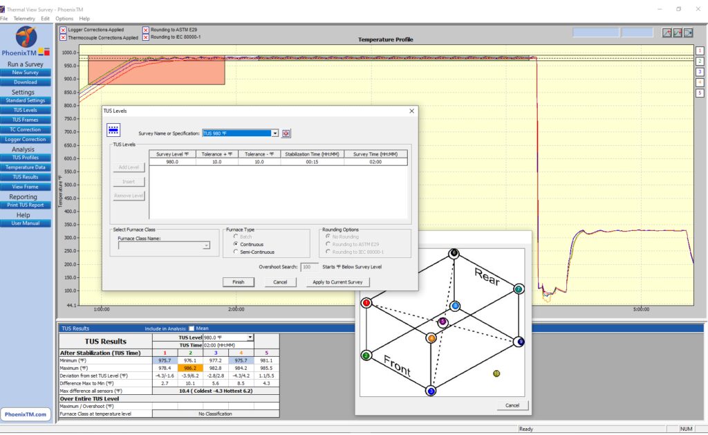
The thru-process monitoring principle allows for an efficient method by which the TUS can be performed employing a TUS frame to position a defined number of thermocouples over the specific working zone of the furnace (product basket). As defined in the standard with particular reference to application assessment process Table C (aluminum heat treating), the uniformity for both the solution heat treatment and aging furnace needs to be proven to satisfy ±10°F of the threshold temperature during the soak time.

Complementing the TUS system, the Thermal View Survey software provides a means by which the full survey can be set up automatically allowing routine full analysis and reporting to the CQI-9 specification as shown in Figure 6.

Figure 6. View of TUS for T6 aluminum processing in Phase 1 Solution Re-heat
Source: PhoenixTM

Interestingly, a significant further benefit of the thru-process principle is that by collecting process data for the whole process, many of the additional requirements of the process Table C can be achieved with reference to the quench. From the profile trace, key criteria such as quench media temperature, quench delay time, and quench cooling curve can be measured and reported with full traceability during the production run.

Summary

To fully understand, control, and optimize the T6 heat treat process, it is essential the entire process is monitored. Thru-process monitoring solutions, designed specifically, allow not only product temperature profiling of all the solution heat treatment, water quench, and age hardening phases, but also comprehensive temperature uniformity surveying to comply with CQI-9.

About the Author:

Dr Steve Offley (“Dr O”), Product Marketing Manager, PhoenixTM

Dr. Steve Offley, “Dr. O,” has been the product marketing manager at PhoenixTM for the last five years after a career of over 25 years in temperature monitoring focusing on the heat treatment, paint, and general manufacturing industries. A key aspect of his role is the product management of the innovative PhoenixTM range of thru-process temperature and optical profiling and TUS monitoring system solutions.

For more information: Contact Steve at Steve.Offley@phoenixtm.com.


Find Heat Treating Products And Services When You Search On Heat Treat Buyers Guide.Com


Overcoming Quality Challenges for Automotive T6 Heat Treating Read More »
Advantages of Laser Heat Treatment, Part 2: Energy Efficiency, Sustainability, and Precision

A discussion of laser heat treating begun in Heat Treat Today’s Air & Atmosphere 2024 print edition would not be complete without highlighting key sustainability advantages of this new technology. In this Technical Tuesday installment, guest columnist Aravind Jonnalagada (AJ), CTO and co-founder of Synergy Additive Manufacturing LLC, explores how sustainability and energy-efficiency are driven by precision heat application and minimal to zero distortion. The first part, “Advantages of Laser Heat Treatment: Precision, Consistency, and Cost Savings”, appeared on April 2, 2024, in Heat Treat Today, as well as in Heat Treat Today’s January/February 2024 Air & Atmosphere print edition.

This informative piece was first released in Heat Treat Today’s May 2024 Sustainability Heat Treat print edition.


Laser heat treating is a transformative process that promises superior performance and sustainable practices. Laser heat treating epitomizes precision in surface heat treatment techniques, targeting localized heating of steel or cast-iron components. Laser radiation raises the surface temperature of the metal in the range of 1652°F to 2552°F (900°C to 1400°C), inducing a transformation from ferritic to austenitic structure on the metal surface. As the laser beam traverses the material, the bulk of the component self-quenches the heated zone. During this process, carbon particles are deposited in the high temperature lattice structure and cannot diffuse outward because of quick cool down resulting in the formation of hard martensite to a case depth up to 0.080” (2 mm), crucial for enhancing material properties.

Sustainability through Energy Efficiency

Contact us with your Reader Feedback!

When considering the energy consumption of a typical laser heat treating operation, it’s essential to acknowledge the continuous advancements in laser technology. Modern laser heat treating systems integrate high-power lasers, water chillers, and motion systems, such as robots or CNC machines. With a typical wall plug efficiency of around 50% for diode lasers, these systems represent a significant improvement in energy utilization compared to conventional methods. The typical energy consumption cost for running a 6 kW laser heat treating system is $20-$30/day. The calculation is based on an 8-hour shift with a duty cycle of 80% calculated at national average electric cost of 15.45 cents/kilowatt-hour.

Self-Quenching Mechanism

Laser heat treating operates on the essential principle of self-quenching, leveraging the bulk mass of the material for rapid cooling. This eliminates the dependence on quenchants required in flame and induction heat treating processes, further reducing environmental impact and operational costs.

Precision and Minimal Distortion

At the heart of laser heat treating lies its sustainable and energy-efficient attributes, driven by two fundamental features: precision heat application and minimal to zero distortion of components post-heat treatment. When compared to the conventional methods such as flame and induction hardening, laser heat treatment offers significantly localized heating. This precision allows for targeted heat treatment within millimeter precision right where the hardness is needed, optimizing energy utilization and operational efficiency. Furthermore, the high-power density of lasers enables hardening with minimal to zero distortion, eliminating or reducing the need for subsequent machining operations like hard milling or grinding.

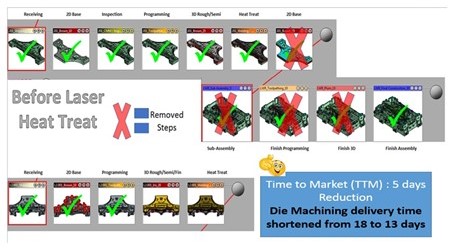
Case Study image; 16 small boxes of auto parts undergoing die machining, laser heat treat; blue inset box
Comparison of the die construction process before and after laser hardening
Source: Autodie LLC

A Case Study of Laser Heat Treating in Automotive Stamping Dies

The image above identifies process steps typically involved in construction of automotive stamping dies. During the process of manufacturing automotive stamping dies, the cast dies are first soft milled, intentionally leaving between 0.015” and 0.020” of extra stock material on the milled surfaces. This is done to account for any distortions that will result from the subsequent conventional heat treatment processes such as flame or induction. After heat treating, the dies are then hard milled back to tolerance and assembled.

In the laser heat treating process, by contrast, dies are finish machined to final tolerance in the first step and then laser heat treated without distortion. No secondary hard milling operation is necessary. Typical cost savings for our automotive tool and die customer exceeds over 20% due to elimination of hard milling operation. Total energy reduction is significant, although not computed here. This may result in savings if carbon credits become monetized.

Laser heat treating’s precision, efficiency, and minimal environmental footprint position it as an environmentally friendly option for heat treat operations. As industries continue to prioritize sustainability, laser heat treating may set new standards for excellence and environmental stewardship.

About the Author:

Aravind Jonnalagadda
CTO and Co-Founder
Synergy Additive Manufacturing LLC
Source: LinkedIn

Aravind Jonnalagadda (AJ) is the CTO and co-founder of Synergy Additive Manufacturing LLC. With over 15 years of experience, AJ and Synergy Additive Manufacturing LLC provide high-level laser systems and laser heat treating, specializing in high power laser-based solutions for complex manufacturing challenges related to wear, corrosion, and tool life. Synergy provides laser systems and job shop services for laser heat treating, metal based additive manufacturing, and laser welding.

For more information: Contact AJ at aravind@synergyadditive.com or synergyadditive.com/laser-heat-treating.


Find Heat Treating Products and Services When You Search on Heat Treat Buyers Guide.com


Advantages of Laser Heat Treatment, Part 2: Energy Efficiency, Sustainability, and Precision Read More »
All About the Quench and Keeping Cool: Thru-process Temp Monitoring and Gas Carburizing

The future of heat treating requires new manufacturing solutions like robotics that can work with modular design. Yet so also does temperature monitoring need to be seamless to know how effectively your components are being heat treated — especially through being quenched. In this Technical Tuesday, learn more about temperature monitoring through the quench process.

Gas Carburization

Contact us with your Reader Feedback!

Carburizing has rapidly become one of the most critical heat treatment processes employed in the manufacture of automotive components. Also referred to as case hardening, it provides necessary surface resistance to wear, while maintaining toughness and core strength essential for hardworking automotive parts.

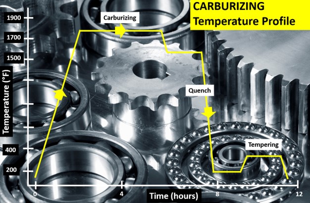
Figure 1. Typical carburizing heat treat temperature profile showing the critical temperature/time steps: (i) carburization, (ii) quench, and (iii) temper. (Source: PhoenixTM)

The carburizing process is achieved by heat treating the product in a carbon rich environment (Figure 1), typically at a temperature of 1562°F–1922°F (850°C–1050°C). The temperature and process time significantly influence the depth of carbon diffusion and other related surface characteristics. Critical to the process is a rapid quenching of the product following the diffusion in which the temperature is rapidly decreased to generate the microstructure, giving the enhanced surface hardness while maintaining a soft and tough product core.

The outer surface becomes hard via the transformation from austenite to martensite while the core remains soft and tough as a ferritic and/or pearlitic microstructure. Normally, carburized microstructures following quench are further tempered at temperatures of about 356°F (180°C) to transform some of the brittle martensite into tempered martensite to enhance ductility and grindability.

Critical Process Temperature Control

As discussed, the success of carburization is dependent on accurate, repeatable control of the product temperature and time at that temperature through the complete heat treatment process. Important to the whole operation is the quench, in which the rate of cooling (product temperature change) is critical to achieve the desired changes in microstructure, creating the surface hardness. It is interesting that the success of the whole heat treat process can rest on a process step which is so short (minutes), in terms of the complete heat teat process (hours). Getting the quench correct is not only essential to achieve the desired metal microstructure, but also to ensure that the physical dimensions and shape of the product are maintained (no distortion/warping) and issues such as quench cracking are eliminated.

Obviously, as the quench is so critical to the whole heat treat process, the correct quench selection needs to be made to achieve the optimum properties with acceptable levels of dimensional change. Many different quenchants can be applied with differing quenching performances. The rate of heat transfer (quench rate) of quench media in general follows this order from slowest to quickest: air, salt, polymer, oil, caustic, and water.

Technology Challenges for Temperature Monitoring

When considering carburization from an industry standpoint, furnace heat treat technology generally falls into one of two camps, embracing either air quench (low pressure carburization) or oil quench (sealed gas carburization/LPC with integral or vacuum oil quench). Although each achieves the same end goal, the heat treat mechanisms and technologies employed are very different, as are the temperature monitoring challenges.

To achieve the desired carburized product, it is necessary to control and hence monitor the product temperature through the three phases of the heat treat process. Conventionally, product temperature monitoring would be attempted using the traditional trailing thermocouple method. For many modern heat treat processes including carburization, the trailing thermocouple method is difficult and often practically impossible.1 The movement of the product or product basket from stage to stage, often from one independent sealed chamber to another (lateral or vertical movement), makes the monitoring of the complete process a significant challenge.

With the industry driving toward fully automated manufacturing, furnace manufacturers are now offering the complete package with full robotic product loading that includes shuttle transfer systems and modular heat treat phases to process both complete product baskets and single piece operations. Although trailing thermocouples may allow individual stages in the process to be measured, they cannot provide monitoring of the complete heat treat journey. Testing is therefore not under true normal production conditions, and therefore is not an accurate record of what happens in normal day to day operation.

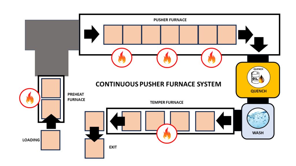
Figure 2 shows schematic diagrams of two typical carburizing furnace configurations that would not be possible to monitor using trailing thermocouples. The first shows a modular batch furnace system where the product basket is transferred between each static heat treat operation (preheat, carburizing furnace, cooling station, quench, quench wash, temper furnace) via a charge transfer cart. The second shows the same heat treat operation but performed in a continuous indexed pusher furnace configuration where the product basket moves sequentially through each heat treat operation in a semi-continuous flow.

Figure 2.1. Modular batch furnace system (Source: PhoenixTM)
Figure 2.2. Continuous pusher furnace schematic (Source: PhoenixTM)

Thru-process temperature monitoring as a technique overcomes such technical restrictions. The data logger is protected by a specially designed thermal barrier, therefore, can travel with the product through each stage of the process measuring the product/process temperature with short, localized thermocouples that will not hinder travel. The careful design and construction of the monitoring system is important to address the specific challenges that different heat treat technology brings including modular batch and continuous pusher furnace designs (Figure 2).2

The following section will focus specifically on monitoring challenges of the sealed gas carburizing process with integral oil quench. Technical challenges of the alternative low pressure carburizing technology with high pressure gas quench have previously been discussed in an earlier publication.3

Monitoring Challenges of Sealed Gas Carburization — Oil Quench

Figure 3. “Thru-process” temperature monitoring system for use in a sealed carburizing furnace with integral oil quench — (3.1) Monitoring system entering furnace with thermocouple fixed to automotive gears, product test pieces (3.2) System exiting oil quench tank (3.3) System inserted into wash tank with product basket (Source: PhoenixTM)

Presently, the most common traditional method of gas carburizing for automotive steels is often referred to as sealed gas carburizing. In this method, the parts are surrounded by an endothermic gas atmosphere. Carbon is generated by the Boudouard reaction during the carburization process, typically at 1562°F–1832°F (850°C –1000°C). Despite the dramatic appearance of a sealed gas carburizing furnace, with its characteristic belching flames (Figure 3), from a monitoring perspective, the most challenging aspect of the process is not the heating, but the oil quench cooling. For such furnace technology, the historic limitation of “thru-process” temperature profiling has been the need to bypass the oil quench and wash stations, missing a critical process step from the monitoring operation. Obviously, passing a conventional hot barrier through an oil quench creates potential risk of both system damage from oil ingress and barrier distortion, as well as general process safety. However, the need to bypass the quench in certain furnace configurations by removing the hot system from the confined furnace space could create significant operational challenges, from an access and safety perspective.

Monitoring of the quench is important as ageing of the oil results in decomposition (thermal cracking), oxidation, and contamination (e.g. water) of the oil, all of which degrade the viscosity, heat transfer characteristics, and quench efficiency. Control of physical oil temperature and agitation rates is also key to oil quench performance. Quench monitoring allows economic oil replacement schedules to be set, without risk to process performance and product quality.

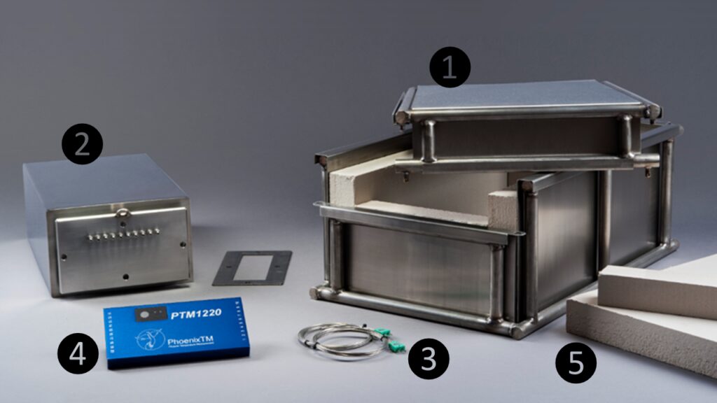
Figure 4. “Thru-process” temperature monitoring system oil quench compatible thermal barrier design: (1) Robust outer structural frame keeping insulation and inner barrier secure; (2) Internal thermal barrier — completely sealed with integral microporous insulation protecting data logger; (3) Mineral insulated thermocouples sealed in internal thermal barrier with oil tight compression fitting; (4) Multi-channel high temperature data logger; and (5) Sacrificial insulation blocks replaced after each run. (Source: PhoenixTM)

To address the process challenges, a unique thermal barrier design has been developed that both protects the data logger in the furnace (typically three hours at 1697°F/925°C) and also protects during transfer through the oil quench (typically 15 mins) and final wash station (Figure 3). The key to the barrier design is the encasement of a sealed inner barrier with its own thermal protection with blocks of high-grade sacrificial insulation contained in a robust outer structural frame (Figure 4).

Quench Cooling Phases

Monitoring the oil quench in carburization gives the operator a unique insight into the product’s specific cooling characteristics, which can be critical to allow optimal product loading and process understanding and optimization. From a scientific perspective, the quench temperature profile trace, although only a couple of minutes in duration, is complex and unique. From a zoomed in quench trace (Figure 5) taken from a complete carburizing profile run, the three unique heat transfer phases making up the oil quench cool curve can be clearly identified:

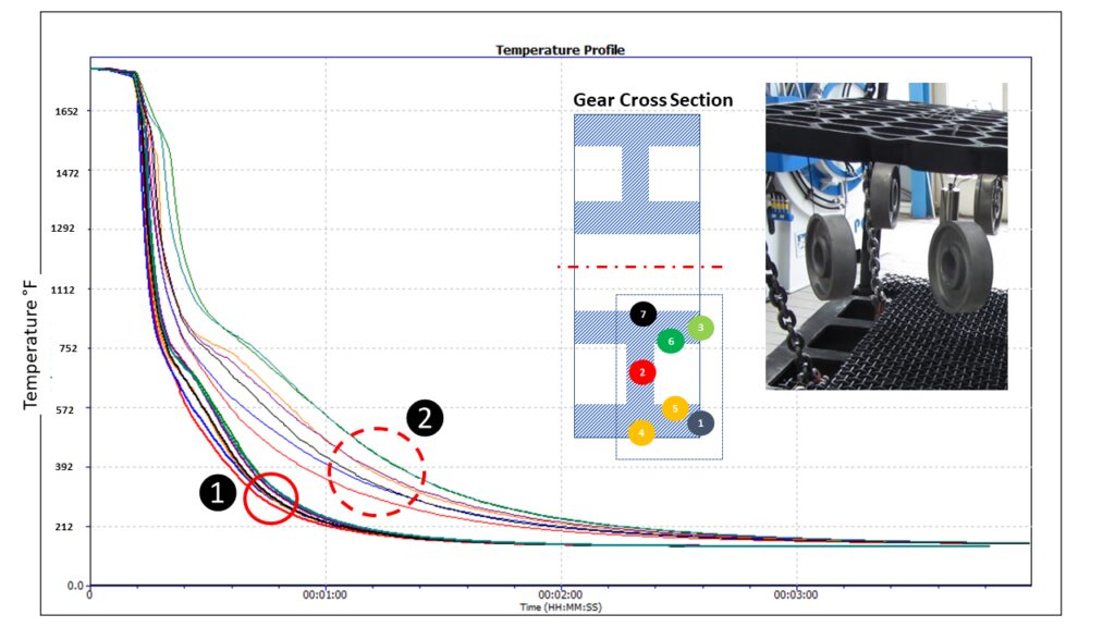
Figure 5. Oil quench temperature profile for different locations on an automotive gear test piece shows the three distinct heat transfer phases: (1) film boiling “vapor blanket”, (2) nucleate boiling, and (3) convective heat transfer. (Source: PhoenixTM)
  1. Film boiling “vapor Blanket”: The oil quenchant creates a layer of vapor (Leidenfrost phenomenon) covering the metal surface. Cooling in this stage is a function of conduction through the vapor envelope. Slow cool rate since the vapor blanket acts as an insulator.
  2. Nucleate boiling: As the part cools, the vapor blanket collapses and nucleate boiling results. Heat transfer is fastest during this phase, typically two orders of magnitude higher than in film boiling.
  3. Convective heat transfer: When the part temperature drops below the oil boiling point. the cooling rate slows significantly. The cooling rate is exponentially dependent on the oil’s viscosity.

From a heat treat perspective, the quench step relative to the whole process (hours) is quick (seconds), but it is probably the most critical to the performance of the metallurgical phase transitions and achieving the desired core microstructure of the product without risk of distortion. By being able to monitor the quench step, the process can be validated for different products with differing size, form, and thermal mass. As shown in Figure 6, the quench curve profile over the three heat transfer phases is very different for two different automotive gear sizes.

Figure 6. Oil quench temperature profile for different automotive gear sizes (20MnCr5 case hardening steel) with different thermal masses: Passenger Car Gear (2.2 lbs) and Commercial Vehicle Gear (17.6 lbs) (Source: PhoenixTM)

Summary

As discussed in this article, one of the key process performance factors associated with gas carburization is the control and monitoring of the product quench step. Employing an oil quench, the measurement of such operation is now very feasible as part of heat treat monitoring. Innovations in thru-process temperature profiling technology offer specific system designs to meet the respective application challenges.

References

[1] Dr. Steve Offley, “The light at the end of the tunnel – Monitoring Mesh Belt Furnaces,” Heat Treat Today, February 2022, https://www.heattreattoday.com/processes/brazing/brazing-technical-content/the-light-at-the-end-of-the-tunnel-monitoring-mesh-belt-furnaces/.

[2] Michael Mouilleseaux, “Heat Treat Radio #102: Lunch & Learn, Batch IQ Vs. Continuous Pusher, Part 1,” interviewed by Doug Glenn, Heat Treat Radio, October 26, 2023, audio, https://www.heattreattoday.com/media-category/heat-treat-radio/heat-treat-radio-102-102-lunch-learn-batch-iq-vs-continuous-pusher-part-1/.

[3] Dr. Steve Offley, “Discover the DNA of Automotive Heat Treat: Thru-process Temperature Monitoring,” Heat Treat Today, August 2023, https://www.heattreattoday.com/discover-the-dna-of-automotive-heat-treat-thru-process-temperature-monitoring/.

About the Author

Dr Steve Offley (“Dr O”), Product Marketing Manager, PhoenixTM

Dr. Steve Offley, “Dr. O,” has been the product marketing manager at PhoenixTM for the last five years after a career of over 25 years in temperature monitoring focusing on the heat treatment, paint, and general manufacturing industries. A key aspect of his role is the product management of the innovative PhoenixTM range of thru-process temperature and optical profiling and TUS monitoring system solutions.

For more information: Contact Steve at Steve.Offley@phoenixtm.com.

Find Heat Treating Products And Services When You Search On Heat Treat Buyers Guide.Com

All About the Quench and Keeping Cool: Thru-process Temp Monitoring and Gas Carburizing Read More »

Advantages of Laser Heat Treatment: Precision, Consistency, and Cost Savings

Laser heat treating, a form of case hardening, offers substantial advantages when distortion is a critical concern in manufacturing operations. Traditional heat treating processes often lead to metal distortion, necessitating additional post-finishing operations like hard milling or grinding to meet dimensional tolerances.

This Technical Tuesday article was originally published in first published in Heat Treat Today’s January/February 2024 Air & Atmosphere print edition.


In laser heat treating, a laser (typically with a spot size ranging from 0.5″ x 0.5″ to 2″ x 2″) is employed to illuminate the metal part’s surface. This results in a precise and rapid delivery of high-energy heat, elevating the metal’s surface to the desired transition temperature swiftly. The metal’s thermal mass facilitates rapid quenching of the heated region resulting in high hardness.

Key Benefits of Laser Heat Treating

Consistent Hardness Depth

Laser heat treatment achieves consistent hardness and hardness depth by precisely delivering high energy to the metal. Multiparameter, millisecond-speed feedback control of temperature ensures exacting specifications are met.

Minimal to Zero Distortion

Due to high-energy density, laser heat treatment inherently minimizes distortion. This feature is particularly advantageous for a variety of components ranging from large automotive dies to gears, bearings, and shafts resulting in minimal to zero distortion.

Precise Application of Beam Energy

Unlike conventional processes, the laser spot delivers heat precisely to the intended area, minimizing or eliminating heating of adjoining areas. This is specifically beneficial in surface wear applications, allowing the material to be hardened on the surface while leaving the rest in a medium-hard or soft state, giving the component both hardness and ductility.

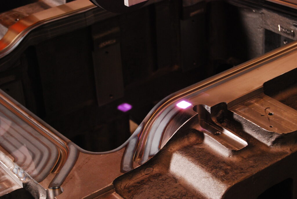
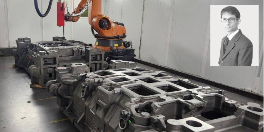
Figure 1. Laser heat treating of automotive stamping die constructed from D6510 cast iron material (Source: Synergy Additive Manufacturing LLC)

No Hard Milling or Grinding Required

The low-to-zero-dimensional distortion of laser heat treatment reduces or eliminates the need for hard milling or grinding operations. Post heat treatment material removal is limited to small amounts removable by polishing. Eliminating hard milling or grinding operations saves substantial costs in the overall manufacturing process of the component. Our typical tool and die customers have seen over 20% cost savings by switching over to laser heat treating.

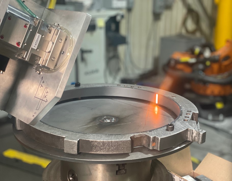
Figure 2. Laser heat treating of machine tool
components (Source: Synergy Additive Manufacturing LLC)

Applicable for a Large Variety of Materials

Any metal with 0.2% or more carbon content is laser heat treatable. Hardness on laser heat treated materials typically reaches the theoretical maximum limit of the material. Many commonly used steels and cast irons in automotive industry such as A2, S7, D2, H13, 4140, P20, D6510, G2500, etc. are routinely laser heat treated. A more exhaustive list of materials is available at synergyadditive.com/laser-heat-treating.

Conclusions

Aravind Jonnalagadda CTO and Co-Founder Synergy Additive Manufacturing LLC Source: LinkedIn

Laser heat treatment is poised to witness increased adoption in the automotive and other metal part manufacturing sectors. The adoption of this process faces no significant barriers, aside from the typical challenges encountered by emerging technologies, such as lack of familiarity, limited hard data, and a shortage of existing suppliers. The substantial savings, measured in terms of cost, schedule, quality, and energy reduction, provide robust support for the continued embrace of laser heat treatment in manufacturing processes.

For more information: Contact AJ at aravind@synergyadditive.com or synergyadditive.com/laser-heat-treating.

Find Heat Treating Products And Services When You Search On Heat Treat Buyers Guide.com 

Advantages of Laser Heat Treatment: Precision, Consistency, and Cost Savings Read More »
Aluminum Extrusion Operations Bring Nitriding In-House

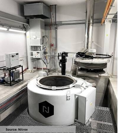
Extral SP. Z o.o., a Polish company specializing in aluminum extrusions, has bolstered its manufacturing capabilities to better serve the construction, automobile, and machinery industries. Alongside acquiring a new aluminum extrusion press, the company ordered a nitriding system to nitride H11 and H13 extrusion dies of various sizes.

Nitriding pit furnace from Nitrex

The Nitrex turnkey nitriding system includes an NX-1015 pit-type furnace with a 2-ton (4410-lb) load capacity and NITREG® technology, offering nitriding treatments that optimize die performance and throughput while concurrently reducing tooling costs.

This investment coincides with Extral’s expansion of its operational footprint in Poland, including the construction of a new building to house the extrusion press and furnace. This expansion enables the company to diversify its range of extruded products while maintaining a focus on sustainability and energy efficiency. The new nitriding installation will contribute to these objectives by providing more efficient use of process gases and electricity.

Marcin Stokłosa
Project Manager
Nitrex Poland
Source: LinkedIn.com

Previously, Extral outsourced its nitriding operations to a local heat treater, due to quality issues encountered with an underperforming in-house nitriding unit. However, this latest investment enables them to bring nitriding operations back in-house, ensuring better control over the quality and consistency of their nitrided dies while also benefiting from expedited turnaround times.

Marcin Stoklosa, project manager at Nitrex, said, “Working with Extral on this project has been a pleasure. . . . Seeing customers invest in their business and achieve their goals, especially when it aligns with our values of innovation and sustainability, is always rewarding.”

This press release is available in its original form here.


Find Heat Treating Products And Services When You Search On Heat Treat Buyers Guide.Com

Aluminum Extrusion Operations Bring Nitriding In-House Read More »

Common Automotive Heat Treat Processes To Get Into Gear

How long have you been heat treating automotive gears? Which thermal processing techniques do your operations gravitate towards? In this best of the web article, uncover some of the common heat treatment functions and the properties they create in gears. Let us know what you think of this general overview of the world of heat treating gears in our Reader Feedback form!

Contact us with your Reader Feedback!

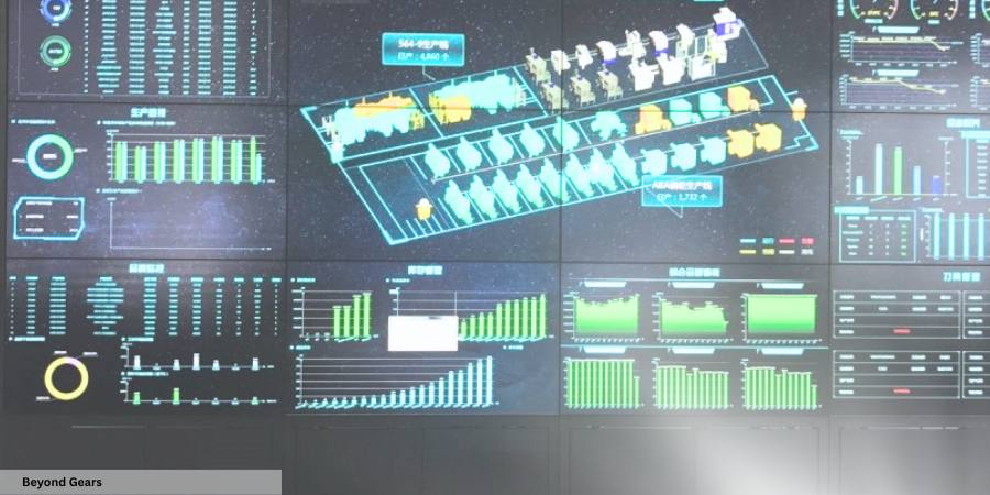
Additionally, when you read to the end of the article, future trends that we can anticipate for heat treaters in the automotive industry are offered; as one might guess, they include digital and energy-saving technologies.

An excerpt: “Automotive gear heat treatment (process) includes two aspects: firstly, conventional heat treatment such as annealing, normalizing, quenching, tempering, and quenching and tempering; secondly, surface heat treatment, which encompasses methods like surface quenching (e.g., induction quenching, laser quenching) and chemical heat treatment (e.g., carburizing, carbonitriding, nitriding, nitrocarburizing).”

Read the entire article from Beyond Gears via LinkedIn, by clicking here: “Characteristics and Development Trends in Automotive Gear Heat Treatment


Find Heat Treating Products And Services When You Search On Heat Treat Buyers Guide.Com

Common Automotive Heat Treat Processes To Get Into Gear Read More »
Thermal Loop Solutions, Part 1: A Path to Improved Performance and Compliance in Heat Treatment

How often do you think about the intelligent designs controlling the thermal loop system behind your heat treat operations? With ever-advancing abilities to integrate and manage data for temperature measurement and power usage, the ability of heat treat operations to make practical, efficient, and energy-conscious change is stronger than ever. In part 1, understand several benefits of thermal loop systems and how they are leveraged to comply with industry regulations, like Nadcap.

This Technical Tuesday article by Peter Sherwin, global business development manager – Heat Treatment, and Thomas Ruecker, senior business development manager, at Watlow was originally published in Heat Treat Today’s January/February 2024 Air & Atmosphere Heat Treat print edition.


Introduction

Heat treatment processes are a crucial component of many manufacturing industries, and thermal loop solutions have become increasingly popular for achieving improved temperature control and consistent outcomes.

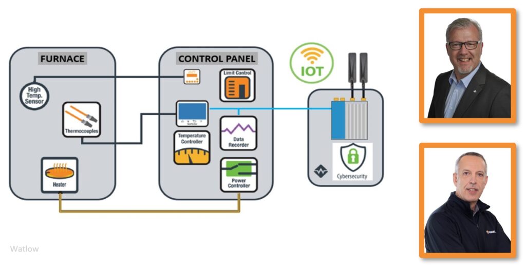
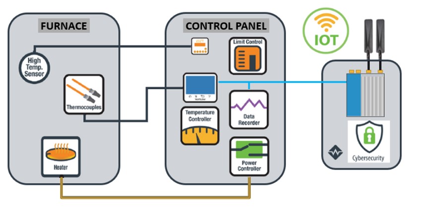
A thermal loop solution is a closed loop system with several essential components, including an electrical power supply, power controller, heating element, temperature sensor, and process controller. The electrical power supply provides the energy needed for heating, the power controller regulates the power output to the heating element, the heating element heats the material, and the temperature sensor measures the temperature. Finally, the process controller adjusts the power output to maintain the desired temperature for the specified duration, providing better temperature control and consistent outcomes.

Performance Benefits

Heat treatment thermal loop solutions offer several advantages over traditional heat treatment methods, including improved temperature control and increased efficiency. The thermal loop system provides precise temperature control, enabling faster heating and cooling and optimized soak times. In addition, the complete design of modern thermal loop solutions includes energy-efficient heating and overall ease of use.

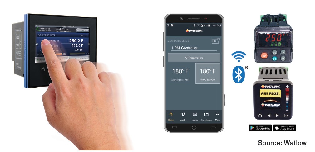
Figure 1. Watlow Industry 4.0 solution (Source: Watlow)

Heat treatment thermal loop solutions are integrated with Industry 4.0 frameworks and data management systems to provide real-time information on performance. Combining artificial intelligence and machine learning algorithms can also provide additional performance benefits, such as the ability to analyze data and identify patterns for further optimization. Ongoing performance losses in a heat treatment system typically come from process drift s. Industry 4.0 solutions can explore these drift s and provide opportunities to minimize these deviations.

Heat treatment thermal loop solutions can be optimized using Failure Mode and Effects Analysis (FMEA). FMEA is a proactive approach to identifying potential failure modes and their effects, allowing organizations to minimize the risk of process disruptions and improve the overall efficiency of their heat treatment processes. Historically, this was a tabletop exercise conducted once per year with a diverse team from across the organization. Updates to this static document were infrequent and were primarily based on organization memory rather than being automatically populated in real time with actual data. There is a potential to produce “live” FMEAs utilizing today’s technology and leveraging insights for continuous improvement.

Th e effectiveness of heat treatment thermal loop solutions can be measured using metrics such as overall equipment effectiveness (OEE). OEE combines metrics for availability, performance, and quality to provide a comprehensive view of the efficiency of a manufacturing process. By tracking OEE and contextual data, organizations can evaluate the effectiveness of their heat treatment thermal loop solutions and make informed decisions about optimizing their operations.

Regulatory Compliance

Nadcap (National Aerospace and Defense Contractors Accreditation Program) is an industry-driven program that provides accreditation for special processes in the aerospace and defense industries. Heat treatment is considered a “special process” under Nadcap because it has specific characteristics crucial to aerospace and defense components’ quality, safety, and performance. Th ese characteristics include:

  • Process sensitivity: Heat treatment processes involve precise control of temperature, time, and atmosphere to achieve the desired material properties. Minor variations in these parameters can significantly change the mechanical and metallurgical properties of the treated components. This sensitivity makes heat treatment a critical process in the aerospace and defense industries.
  • Limited traceability: Heat treatment processes typically result in changes to the material’s microstructure, which are not easily detectable through visual inspection or non-destructive testing methods. Th is limited traceability makes it crucial to have strict process controls to ensure the desired outcome is achieved consistently.
  • Critical performance requirements: Aerospace and defense components often have strict performance requirements due to the extreme conditions in which they operate, such as high temperatures, high loads, or corrosive environments. The heat treatment process ensures that these components meet the specifications and can withstand these demanding conditions.
  • High risk: The failure of a critical component in the aerospace or defense sector can result in catastrophic consequences, including loss of life, significant financial loss, and reputational damage. Ensuring that heat treatment processes meet stringent quality and safety standards is essential to mitigate these risks.

Nadcap heat treatment accreditation ensures suppliers meet industry standards January/February and best practices for heat treatment processes. The accreditation process includes rigorous audits, thorough documentation, and ongoing process control monitoring to maintain high quality, safety, and performance levels.

The aerospace industry’s AMS2750G pyrometry specification and the automotive industry’s CQI-9 4th Edition regulations are crucial for ensuring consistent and high-quality heat treated components. Adherence to these regulations is essential for meeting the stringent quality requirements of the aerospace and automotive industries and other industries with demanding specifications.

Temperature uniformity is a crucial requirement of both AMS2750G and CQI-9 4th Edition, mandating specific temperature uniformity requirements for heat treating furnaces to ensure the desired mechanical properties are achieved throughout the treated components. AMS2750G class 1 furnaces with strict uniformity requirements +/-5°F (+/-3°C) provide both quality output and predictable energy use. However, maintaining this uniformity requires significant maintenance oversight due to all the components involved in the thermal loop.

Calibration and testing procedures are specified in the standards to help ensure the accuracy and reliability of the temperature control systems used in heat treat processes.

Detailed process documentation is required by AMS2750G and CQI-9 4th Edition, including temperature uniformity surveys, calibration records, and furnace classifications. This documentation ensures traceability, enabling manufacturers to verify that the heat treat process is consistently controlled and meets the required specifications.

Figure 2. Eurotherm data reviewer (Source: Watlow)

Modern data platforms enable the efficient collection of secure raw data (tamper-evident) and provide the replay and reporting necessary to meet the standards.

The newer platforms also offer the latest industry communication protocols – like MQTT and OPC UA (Open Platform Communications Unified Architecture) – to ease data transfer across enterprise systems.

MQTT is a lightweight, publish-subscribe-based messaging protocol for resource-constrained devices and low-bandwidth, high-latency, or unreliable networks. IBM developed it in the late 1990s, and it has become a popular choice for IoT applications due to its simplicity and efficiency. MQTT uses a central broker to manage the communication between devices, which publish data to “topics,” and subscribe to topics that they want to receive updates on.

OPC UA is a platform-independent, service-oriented architecture (SOA) developed by the OPC Foundation. It provides a unified framework for industrial automation and facilitates secure, reliable, and efficient communication between devices, controllers, and software applications. OPC UA is designed to be interoperable across multiple platforms and operating systems, allowing for seamless integration of devices and systems from different vendors. The importance of personnel and training is emphasized by CQI-9 4th Edition, which requires manufacturers to establish training programs and maintain records of personnel qualifications to ensure that individuals responsible for heat treat processes are knowledgeable and competent. With touchscreen and mobile integration, a significant development in process controls has occurred over the last decade.

Figure 3. Watlow F4T® touchscreen and Watlow PM PLUS™ EZ-LINK®
mobile application

By integrating these regulations into a precision control loop, heat treatment thermal loop solutions can provide the necessary level of control and ensure compliance with AMS2750G and CQI-9 4th Edition, leading to the production of high-quality heat treated components that meet performance requirements and safety standards.

Continuous improvement is also emphasized by both AMS2750G and CQI-9 4th Edition, requiring manufacturers to establish a system for monitoring, measuring, and analyzing the performance of their heat treatment systems. This development enables manufacturers to identify areas for improvement and implement corrective actions, ensuring that heat treat processes are continuously improving and meeting the necessary performance and safety standards.

To Be Continued in Part 2

In part 2 of this article, we’ll consider the improved sustainability outcomes, potential challenges and limitations, and the promising future this technology offers to the heat treat industry.

About the Authors

Peter Sherwin, Global Business Development Manager – Heat Treatment, Watlow
Thomas Ruecker, Senior Business Development Manager, Watlow

Peter Sherwin is a global business development manager of Heat Treatment for Watlow and is passionate about offering best-in-class solutions to the heat treatment industry. He is a chartered engineer and a recognized expert in heat treatment control and data solutions.

Thomas Ruecker is the business development manager of Heat Treatment at Eurotherm Germany, a Watlow company. His expertise includes concept development for the automation of heat treatment plants, with a focus on aerospace and automotive industry according to existing regulations (AMS2750, CQI-9).

For more information: Contact peter.sherwin@watlow.com or thomas.ruecker@watlow.com.

This article content is used with the permission of heat processing, which published this article in 2023.


Find Heat Treating Products And Services When You Search On Heat Treat Buyers Guide.Com

Thermal Loop Solutions, Part 1: A Path to Improved Performance and Compliance in Heat Treatment Read More »