In this installment of Answers in the Atmosphere, David (Dave) Wolff, an independent expert focusing on industrial atmospheres for heat treat applications, examines what furnace owners should expect when their gas supplier conducts a technical assessment. Drawing on insights from Messer LLC, Wolff walks through the step-by-step process suppliers use to diagnose furnace atmosphere issues, from verifying process parameters to running detailed diagnostic surveys, and outlines the standards of technical competence, communication, and accountability that furnace owners should hold their industrial gas partners to.
This informative piecewas first released in Heat Treat Today’sAugust 2026 Annual Automotive Heat Treating print edition.
This column picks up the conversation leveraging the technological know-how of your gas supplier. If you missed it, read Part 1 in the Heat Treat Super Brands (July 2026) print edition. What follows are the insights and best practices that Messer LLC shared with me on what you need to prepare for a technical assessment with your supplier.
Technical Assessment
First, since business models vary throughout the industry, be sure you understand whether or not technical support will entail a specific fee. When establishing your gas supply contract, furnace owners should seek out suppliers who provide a flexible approach that will be aligned with their needs.
A supplier will often follow these steps when providing technical support to identify, prevent, or correct issues in your heat treat furnace:
Define and verify the problem to determine whether it originates from heat treatment, material handling, or operator error.
Verify incoming material to ensure the issue is not caused by raw material condition or pre-processing steps.
Check heat treatment process control parameters.
Verify furnace atmosphere integrity, inspecting gas supply lines, furnace connections, piping leaks, deliveries, and any repairs.
Evaluate furnace component, identify any changes in furnace structure or maintenance activities.
Review process parameters to confirm whether temperature, time, gas composition, or gas purity have changed.
Inspect exhaust systems, doors, and airflow, as disturbances can impact furnace performance.
After reviewing initial process data, a furnace atmosphere survey or targeted spot check may be conducted. This step may include:
Establishing furnace baseline conditions
Running furnace temperature profile tests
Measuring oxygen, CO, CO2, hydrogen content, and dew point
Conducting detailed modeling based on gas flows, heat transfer, or mass balances
Your provider may use advanced tools, such as Computational Fluid Dynamics (CFD) modeling, to analyze and resolve complex furnace atmosphere issues.
What to Expect: Evaluating Supplier Capabilities
Not all technical support delivers the same value. While many suppliers have strong technical capabilities, access can vary based on internal structures or business models. Some suppliers provide expanded support.
Furnace owners should expect their industrial gas partner to:
Demonstrate strong technical competence and ability to identify root causes
Communicate clearly in practical terms familiar to operations teams
Deliver recommendations with a complete implementation plan including safety, training, costs, timelines, risks, and benefits
Clearly define responsibilities between the furnace owner and gas provider
Final Thoughts
For furnace owners, the industrial gas supply space can seem like a lot of the same offerings, but a closer look at how technical support varies from one supplier to the next can significantly fine tune your operation’s ability to adapt and respond to your furnace needs. The key is to be honest about what your own operations can accomplish on its own before reviewing industrial gas contracts (more on contracts in the June 2026 “Answers in the Atmosphere” installment) and committing to a too low or too flexible plan for technical support.
About The Author:
David (Dave) Wolff Industrial Gas Professional Wolff Engineering
Dave Wolff has over 40 years of project engineering, industrial gas generation and application engineering, marketing, and sales experience. Dave holds a degree in engineering science from Dartmouth College. Currently, he consults in the areas of industrial gas and chemical new product development and commercial introduction, as well as market development and selling practices.
What if durable hydrogen production design was approached from the standpoint of optimizing data analysis and controls management? When addressed as such, onsite generation can simplify deployment, reduce upfront integration risk, and enable flexible scaling for applications ranging from backup power to industrial processing. Anya Bharadwaj, product manager at Fourier Earth, examines how two North American heat treating operations — one induction, the other sintering — have leveraged software-defined modularized hydrogen to capture these advantages.
This informative piece was first released in Heat Treat Today’sApril 2026 Annual Induction Heating & Melting print edition.
In the high-stakes world of advanced manufacturing, the atmosphere inside a furnace is as critical as the temperature. For decades, manufacturers have been tethered to a legacy, delivery-based model for their hydrogen supply. This energy ecosystem is increasingly showing its age, plagued by hazardous storage conditions, supply chain shocks, and logistical costs that can balloon to 7–10x the actual production costs.
Recent changes in modular electrolyzer technology challenge the delivery-based hydrogen model by enabling on-site generation directly at industrial facilities. One such approach seeks to reimagine energy distribution and storage — when, and how it is needed most. Two case studies illustrate how intelligent, software-defined systems improve reliability, reduce logistical risk, and better align supply with real-time process demand.
Achieving Scalability with PEM Electrolyzers
This system utilizes Proton Exchange Membrane (PEM) electrolyzers to split water into hydrogen and oxygen by applying electricity across a solid polymer electrolyte membrane. Water is fed to the anode side, where oxygen is ionized into positively charged ions (protons) and negatively charged ions (electrons). The protons pass through the membrane while electrons travel through an external circuit (creating the electrical loop). The protons recombine at the cathode to form hydrogen gas.
PEM systems are well-suited for dynamic operations because they respond quickly to changes in power input, operate at relatively high current densities, and produce high-purity hydrogen without requiring a separate gas purification step.
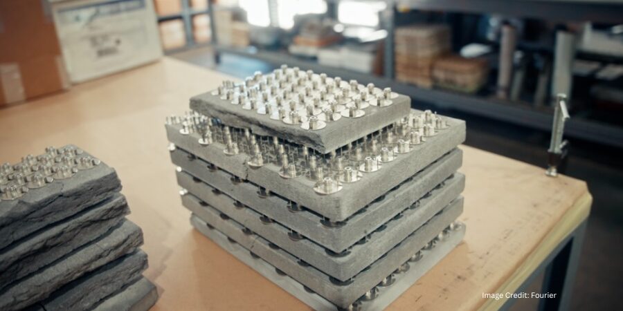
Figure 2. Fourier electrolyzer system displayed at customer site | Image Credit: Fourier
Unlike large, monolithic MW-scale electrolyzers that are complex to integrate and difficult to optimize, PEM stacks can be designed in modular units (Figure 2). Electrolyzer efficiency does not inherently improve with size, so instead of scaling up into single massive systems, the design is scaled out — splitting capacity across many smaller modules without sacrificing performance. Modularization improves lifetime and efficiency since each stack can operate at its optimal temperature, pressure, and current density.
In this architecture, variables in hydrogen production across hundreds or thousands of stacks need to be controlled and optimized. Fourier’s software-defined energy system materialized from seeing hydrogen production as a data and controls problem first and foremost. This hardware-software feedback loop combines machine learning and modular hardware to monitor and control such variables as temperature, pressure, and density.
While on-site hydrogen generation overcomes centralized hydrogen production challenges, seamless integration requires a system that functions as a distributed, intelligent energy resource. The modular architecture is driven by advanced algorithms that optimize performance in real-time, constantly adjusting to deliver peak efficiency and reliability. For modern heat treat operations, this is a crucial step to overcome the technical and commercial barriers due to transportation challenges and volatile industrial gas pricing.
Case Study 1: The Heat Treatment Facility
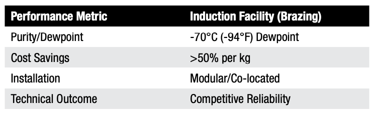
Table A. Performance metrics for induction brazing
The primary objective of the first pilot deployment at an induction heat treatment facility in Southern California was to generate a supply that matched the rigorous reliability and purity requirements of their brazing process. For high value components being induction brazed, hydrogen removes surface oxides from metals, preventing oxidation and improving the quality of the heated workpiece. Any supply interruption or purity dip can compromise their integrity.
In September 2025, the first modular electrolyzer unit was deployed (Figure 1). The integration process involved:
Direct connectivity: The unit co-located at the site and connected directly to the existing electric panel and water supply.
Zero-disruption tie-in: The system integrated directly into the facility’s existing hydrogen manifold, essentially replacing the delivery truck with a continuous on-site stream.
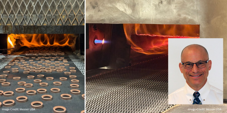
Technical excellence: Over a four-week pilot, the system met stringent specs — a -70°C (-94°F) dewpoint and 60 PSI pressure — supplying hydrogen for two brazing furnaces.
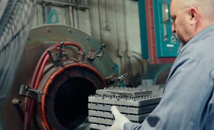
Figure 1. Metal parts being loaded into furnace running on Fourier hydrogen at heat treatment facility, CA | Image Credit: Fourier
During the pilot, hydrogen quality was monitored through continuous dew point and pressure sensing, with all data aggregated into a central dashboard to track moisture levels, delivery stability, and overall system performance in real time. Dew point served as a critical indicator of gas dryness, since excess moisture would directly increase oxidation risk at high-temperature induction heating. Pressure monitoring ensured steady flow and confirmed system integrity throughout each run.
Although a formal gas chromatography was not conducted during the pilot, purity was validated through application-level outcomes. Each treated batch of metal was inspected post-processing, and clean, bright surfaces were consistently observed without scale, pitting, or discoloration. Because hydrogen acts as a reducing atmosphere, even minor deviations in moisture or composition would quickly appear as visible defects. This aligned with stable sensor data and consistent operating conditions. This real-world validation is commercially meaningful: in induction heating, surface quality directly affects downstream machining, coating adhesion, and yield. Demonstrating repeatable, oxide-free results confirms both technical robustness and economic value under actual production conditions.
The successful proof-of-concept achieved industrial-grade performance and reduced costs by more than 50% on a dollar-per-kilogram basis compared to what the client was paying under the existing hydrogen contract.
Case Study 2: Compax, Inc.
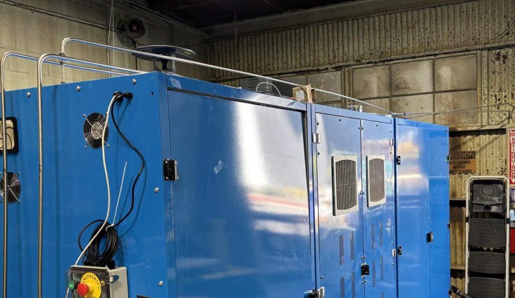
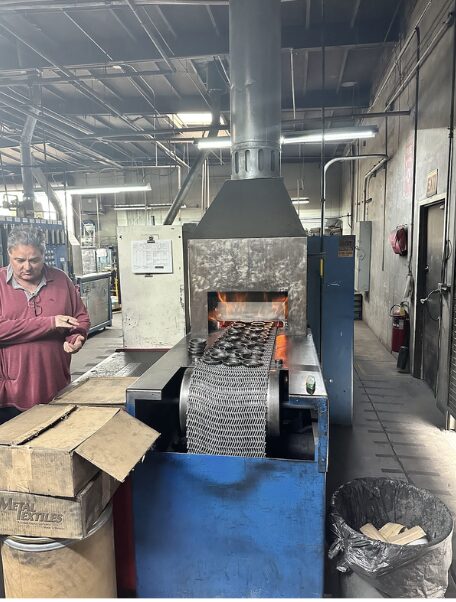
Figure 3. Furnace running on Fourier hydrogen at powder metal plant, Compax, CA | Image Credit: Fourier
For the second pilot development at Compax, Inc., a leader in powdered metal manufacturing located in Southern California, the challenge centered on sintering. Compax uses hydrogen to eliminate oxygen during the heat treating process (Figure 3). The facility faced frequent price hikes and the looming threat of supply disruptions that could halt their belt sintering furnaces, a risk the company sought to eliminate.
The pilot deployment at Compax in November 2025 further proved the scalability of the design — modular units inspired by the data center world, easily configured to specific site needs. The integration process involved:
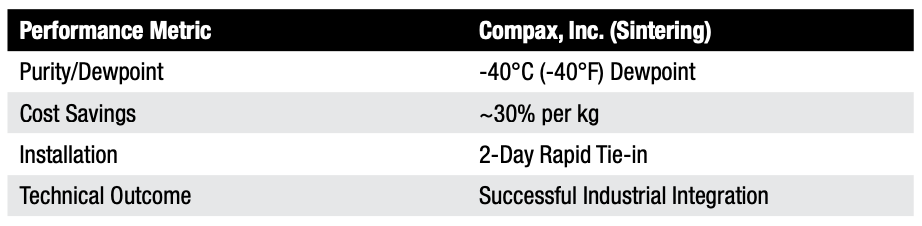
Rapid deployment: Within just two days, the team fully brought the system online in Compax’s utility infrastructure.
Tailored performance: The system delivered a flowrate of 255 SCFH at a -40°C (-40°F) dewpoint and 10 PSI, precisely optimized for the powdered metal sintering process.
Operational control: According to Earl Johnson, CEO of Compax, the system “reliably produced hydrogen…without the hassle of transportation,” adding that it provided much needed “flexibility against frequent increases in industrial gas prices.”
Table B. Performance metrics for sintering
Implications for Industrial Heat Treating
Both pilots achieved a structural advantage by removing logistical constraints, proving that this type of software-enabled hydrogen generation is a viable, cost-effective solution for industrial decarbonization.
By shifting from a centralized commodity model to a distributed, intelligent energy resource, manufacturers gain more than cheaper gas; they gain independence from hydrogen delivery. As the heat treat industry faces increasing pressure to decarbonize while maintaining razor-thin margins, modular, data-driven approaches offer a practical solution, lowering local emissions and ensuring on-demand production.
About The Author:
Anya Bharadwaj Product Manager Fourier Earth
Anya Bharadwaj is a product manager at Fourier Earth, where she leads product strategy and go-to-market for modular hydrogen electrolyzer systems. Her work focuses on identifying new market opportunities and deploying hydrogen technologies for long-duration energy storage and industrial decarbonization. She holds an MBA from Stanford Graduate School of Business and previously worked in energy investment.
In this installment of Answers in the Atmosphere, David (Dave) Wolff, an independent expert focusing on industrial atmospheres for heat treat applications, examines the powerful reducing properties and high thermal conductivity that make hydrogen a critical atmosphere in metal thermal processing.
This informative piece on hydrogen’s role in sintering, annealing, and surface protection — including how it is sourced, how it behaves inside the furnace, and how operations can safely manage this flammable atmosphere under NFPA 86 —was first released in Heat Treat Today’sApril 2026 Annual Induction Heating & Melting print edition.
Hydrogen is widely used in metal thermal processing for sintering of powdered metal fabrication technologies and for heat treatment (e.g., annealing, brazing) of bulk metal manufactured components. This column draws heavily from an interview the author had with Stephen Feldbauer Ph.D., director of Research & Development at Abbott Furnace. Abbott Furnace is a leading furnace manufacturer for continuous furnaces and furnace controls. As R&D Director, Steve leads Abbott’s work in pioneering furnace advances with a special focus on debinding and sintering.
Why Hydrogen?
Stephen Feldbauer, PhD Director of Research & Development Abbott Furnace
Hydrogen provides two desirable characteristics to heat treaters: very high chemical reducing potential and the highest thermal conductivity of any gas. The high reducing potential enables hydrogen to convert heated metal oxide coatings to pure metals. This is extremely helpful for successful sintering of powder metallurgical parts. Superior thermal conductivity enables rapid part heat up and cool down. Compared with either vacuum or inert gas atmospheres, hydrogen enables much faster throughput and achieves shorter furnace cycles.
Hydrogen-containing atmospheres are required to successfully sinter most iron-based metal parts, whether manufactured by powder metallurgy (PM), metal injection molding (MIM), or binder-jet metal additive manufacturing techniques. As-received, the iron-containing metal powders used for these advanced fabrication techniques are covered with an iron-oxide coating, making it virtually impossible to successfully sinter the particles together under reasonable temperature conditions. Reducing the oxide coating enables successful sintering.
Hydrogen-based atmospheres used with a tube or strand furnace are the primary surface protective technology used for drawn components (e.g., wire, tubing, and profiles). Hydrogen simultaneously protects the part surface from oxidation and allows metal to anneal, which softens it and restores toughness after it has been hardened by the drawing process.
Sourcing Hydrogen
Because of its high reactivity, hydrogen is almost never found in nature as a pure gas (H2). Instead, it is generally found as a component in a compound like water (H2O) or a hydrocarbon gas or liquid, such as methane (CH4), propane (C3H8), or longer hydrocarbon. In order to be used as a thermal processing atmosphere, hydrogen is liberated from these hydrogen-containing compounds to exist as a pure gas while in use in the hot furnace.
The liberation of elemental hydrogen from its compound carrier can happen at a remote plant operated by an industrial gas company provider, in which case the hydrogen would be compressed or liquified for delivery to the thermal treatment client, or may be conducted at the site of the thermal processor themselves through use of on-site generation equipment. User choices of approaches to pure hydrogen supply will be covered in future columns.
Inside the Furnace
Inside the hot furnace, hydrogen changes metal oxide coatings to pure metals by preferentially reacting with the metal oxides to produce pure metal and water vapor. Thus, the furnace atmosphere dewpoint (a measure of gaseous water content) will increase as the hydrogen simultaneously creates pure metal surfaces and produces water vapor as a byproduct. The water vapor is swept out of the furnace and replaced by the clean furnace atmosphere that flows counter current to the heated metal product. Furnace atmosphere controls for hydrogen-based atmospheres use dewpoint as a key operating parameter.
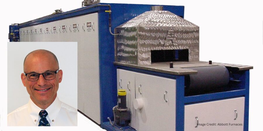
Hydrogen’s ability to protect the part surface from oxidation is critical in the annealing process. | Image Credit: Abbott Furnace
Since furnaces must open to admit parts for thermal processing, the furnace, the atmosphere system, and the procedures must all be designed to prevent unsafe conditions caused by hydrogen leaking out of the furnace, or air leaking in. Furnaces intended for a flammable gas atmosphere use doors, curtains, and pilot lights (i.e., flame curtains) to prevent hydrogen or other flammable gas from leaving the furnace without being combusted. These precautions avoid explosions inside or outside the furnace.
Furnaces for hydrogen-containing atmospheres utilize unique design and construction approaches to safely use this flammable atmosphere. In the U.S., furnace design and operation is guided by NFPA 86, the furnace code. NFPA 86 defines certain furnace design features and also defines standard operating techniques for safe operation with a combustible atmosphere, such as a hydrogen-containing atmosphere. Similar codes and standards are used in other countries.
Next month, this column will pick up the question of cost by looking at options for generation of hydrogen atmosphere blends. Generation of pure hydrogen will be a future topic.
About The Author:
David (Dave) Wolff Industrial Gas Professional Wolff Engineering
Dave Wolff has over 40 years of project engineering, industrial gas generation and application engineering, marketing, and sales experience. Dave holds a degree in engineering science from Dartmouth College. Currently, he consults in the areas of industrial gas and chemical new product development and commercial introduction, as well as market development and selling practices.
Hypersonic vehicles and missiles operating at Mach 5 and beyond place unprecedented thermal and environmental demands on aerospace materials. In this Technical Tuesday installment, Scott Robinson, product manager of ceramics and powder metallurgy at Centorr Vacuum Industries, examines how vacuum and controlled-atmosphere furnaces support the research, prototyping, and production of ultrahigh-temperature ceramics, carbon–carbon composites, and other advanced materials used in hypersonic applications.
This informative piece was first released in Heat Treat Today’sMarch 2026 Annual Aerospace Heat Treating print edition.
Introduction
Hypersonic missiles and vehicles are an emerging class of aerospace technology that is developing rapidly toward active use in military and potentially commercial applications. These machines can achieve sustained speeds of Mach 5 or greater within the Earth’s atmosphere (i.e., at altitudes below about 90 km). While conventional intercontinental ballistic missiles can also achieve hypersonic speeds during atmospheric reentry, they follow a high-arching ballistic trajectory with limited maneuverability, in contrast to the real-time in-flight maneuverability offered by hypersonic systems. As such, military actors prefer hypersonic missiles for precision strikes (Mesa 2024), while in the commercial realm, airliners are excited by the possibility of drastically shortened journey durations with hypersonic vehicles (TomorrowDesk 2025).
Because hypersonic missiles and vehicles move at extreme speeds within Earth’s atmosphere, they are subject to significant atmospheric compression and friction effects (Smith 2021). These effects result in considerable aerodynamic heating of the leading edges, nose tips, and exhaust-washed structures, from 1800°C (3200°F) to more than 3000°C (5400°F).
Traditional aerospace materials such as aluminum, stainless steel, and titanium cannot be used at these elevated temperatures without thermal protection engineering. In contrast, an emerging portfolio of materials including refractory metals, carbon-carbon composites, ultrahigh-temperature ceramics (UHTCs), and ceramic matrix composites (CMCs) can more easily deal with this extreme heat.
UHTCs and CMC materials typically are composed of metal carbides, borides, and nitrides, which means they are traditionally processed at very high temperatures. Currently, the leading candidate materials are silicon carbide (melting/decomposition point: 2730°C, or 4945°F) and zirconium diboride (melting point: ~3246°C, or 5875°F) due in part to their reasonable raw material costs.
Processing of UHTCs, CMCs, and other advanced materials for aerospace applications includes one or more of the following high-temperature processing steps, often using vacuum and controlled atmosphere furnace technology:
Chemical vapor infiltration
Chemical vapor deposition
High-temperature sintering
Graphitization
Silicon melt infiltration of carbon-carbon composites
Each stage of the product development cycle — from laboratory-scale research and development to prototype development to production-scale manufacturing — requires a portfolio of specialized furnaces to achieve the goals of each stage.
This article takes a closer look at the types of furnace solutions available to develop, process, and commercialize these high-performance materials.
Laboratory-Scale Research and Development
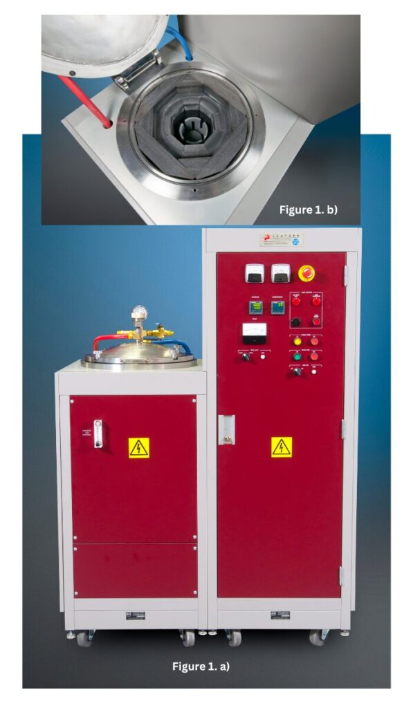
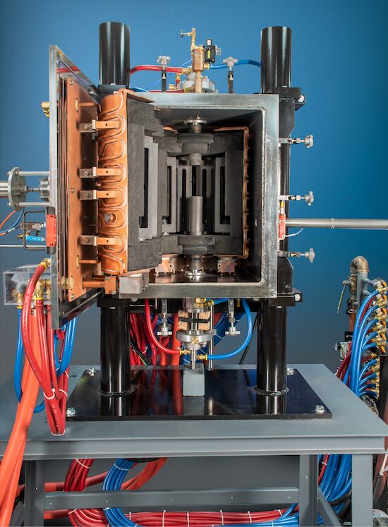
Figure 1. a) Centorr Vacuum Industries’ LF 3000°C (5400°F) graphite vacuum furnace and b) top view of hot zone; 3” x 4” (75 x 100 mm; Ø x h) hot zone. | Image Credit: Centorr Vacuum Industries
Laboratory-scale R&D activities focus mostly on the development, fabrication, and testing of small-scale parts, which require a small, adaptable furnace.
The LF graphite vacuum furnace is an example of the type of furnaces needed for small-scale parts (Figure 1). First designed in 2012, it is a robust, low-cost development furnace with temperature capability up to 3000°C (5400°F) in vacuum or inert gas. This temperature range covers most hypersonic, UHTC, and other applications. For example, current users fit the small 3″ x 4″ (75 x 100 mm; Ø x h) hot zone with small graphite crucibles to fire graphite-based powders for applications in battery and electric vehicle technology.
In another case, Dalhousie University in Nova Scotia, Canada, a research-based university, modified the base LF system by adding a small binder/off-gassing trap and positive pressure exhaust tower for processing of non-oxide ceramics produced by additive manufacturing. These samples include silicon-based ceramics (silicon carbide and silicon nitride), high-entropy ceramics, and cermet systems.
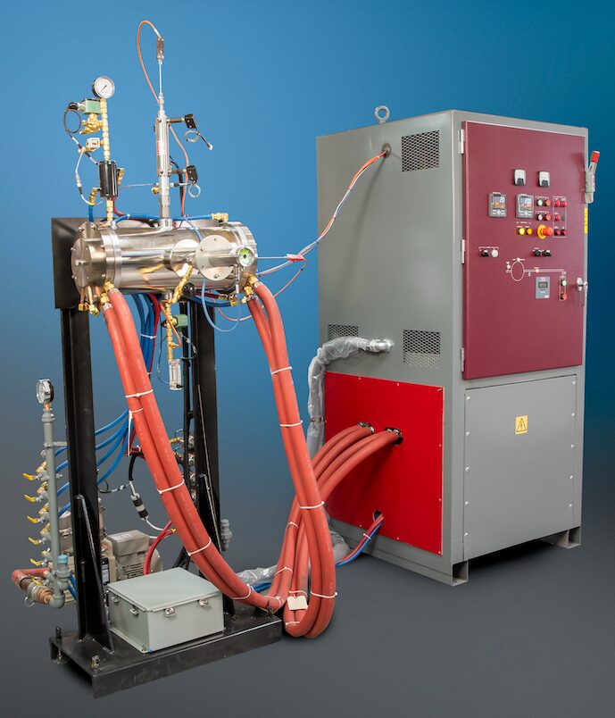
Subsequent laboratory applications require a larger hot zone furnace for processing bigger samples. One example of this type of furnace is the Series 10 graphite tube furnace (Figure 2). This tube furnace is based on a more than 50-year-old furnace design, although the traditional alumina or quartz tube has since been replaced with a solid graphite tube. Operating in vacuum or partial/positive pressures of argon, R&D centers use this furnace to process carbon powder formulations to maximize the percent conversion to graphite, as not all carbon-based starting materials will convert to crystalline graphite.
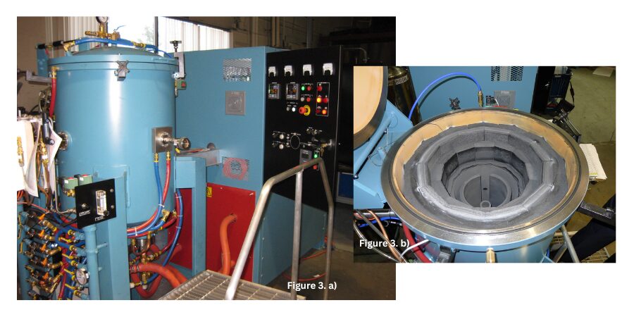
Figure 2. Series 10 3000°C (5400°F) graphite tube furnace; 4″ x 16″ (100 mm x 400 mm) hot zone diameter and height. Image Credit: Centorr Vacuum Industries Figure 3. a) Series 45 graphite top-loading furnace and b) top view of hot zone. Used for carbon/graphite work, this model offers a larger useable firing footprint at higher temperatures than the Series 10 furnace. The hot zone diameter and height dimensions approximate 6″ x 6″ (150 mm x 150 mm), and temperature is rated for 3200°C (5790°F). | Image Credit: Centorr Vacuum Industries
As R&D activities begin to focus on particular material compositions, larger furnaces are needed to synthesize meaningful sizes and quantities of candidate materials prior to scaling up for manufacture, like the Series 45 graphite top-loading furnace (Figure 3).
Characterization and Prototyping Stage
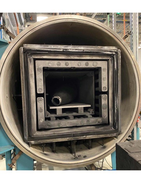
Figure 4. Front view of the Series TT Testorr graphite hot zone rated for 2700°C (4890°F) processing temperatures | Image Credit: Centorr Vacuum Industries
Once the final candidate materials are processed, aerospace design engineers need to test meaningfully sized samples of the materials at high temperature under mechanical loading. It is best to have a furnace that can be combined with mechanical test stands to take measurements of mechanical properties. This is the case for Wichita State University’s National Institute for Aviation Research, which leverages multiple Testorr® furnace units to measure tension, compression, and shear properties of ceramic matrix composites, refractory metals, and other materials at high temperature. Rated for temperatures up to 2700°C (4890°F) in vacuum or inert gas, the furnace can better simulate some aspects of hypersonic service environments (Figure 4).
An important task of the R&D and prototyping stages is to work out processing parameters that will be translated to production-scale manufacturing processes. For example, simple carbon structures will react with air during reentry and suffer damaging effects at temperatures as low as 500°C (930°F). Therefore, any carbon-carbon materials or solid carbon shapes used in hypersonic applications must be protected with advanced ceramic coatings for durability and oxidation resistance.
Chemical vapor deposition is one such coating deposition process, and one of the most popular protective coatings is silicon carbide. The coating is deposited on substrate parts by flowing hydrogen gas through a bubbler of liquid methyltrichlorosilane (MTS; CH3SiCl3) gas. Newer systems use a heated evaporator to vaporize the MTS liquid in a hydrogen carrier gas stream. The combination of hydrogen and MTS is introduced at partial pressures into the furnace hot zone inside a graphite retort, where the gases “crack” or decompose, depositing microns-thick coatings of silicon carbide onto the part’s surface.
Production Stage
Once the advanced materials are properly characterized and prototyped, it is time to look at equipment for full-scale production manufacturing. The furnace configurations for these processes can be conventional front-loading designs or may be oriented in vertical top- or bottom-loading designs for floor space savings and gas flow dynamics.
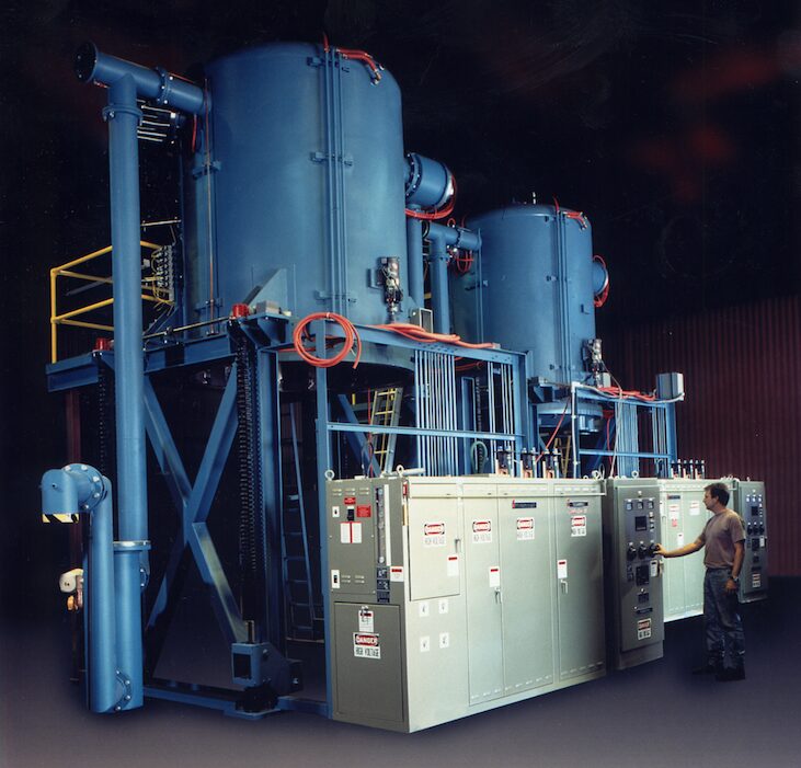
The Sintervac® front-loading graphite furnace (Figure 5) has integral graphite retort and dual gas flow to the main chamber and retort. These furnace systems include durable rotary piston pumping systems with inline binder traps and particulate filters to protect the pumping systems from damage from abrasive ceramic particulates. The internal graphite retort compartmentalizes the off-gassing that takes place and prevents it from escaping into the hot zone, where the oxide byproducts can attack and degrade the graphite heating elements and rigid graphite board insulation.
One common application for this type of furnace is melt infiltration of carbon-carbon composites to improve the physical properties and oxidation resistance of the composite. When processed in partial pressures (or even at positive pressures) of argon, silicon will melt at approximately 1450°C (2640°F). The silicon liquid and vapor infiltrate into the void spaces of the porous carbon-carbon composite via capillary action. The infiltrated silicon reacts with the free carbon in the carbon-carbon fiber structure, forming a silicon carbide matrix around the carbon-carbon fiber structure.
Firms like Exothermics (Amherst, NH) use this process for missile and aerospace applications. The silicon carbide matrix structure provides an environmental barrier to oxidation during reentry into Earth’s atmosphere and improves the matrix’s temperature performance to approximately 1600°C (2910°F) in air.
Smaller production units were also developed for carbon-carbon work at temperatures from 2450°C and 2600°C (4440°F and 4710°F). The addition of dedicated water-cooled filtration traps and 10-μ particulate filters helps deal with the heavy off-gassing expected from processing of carbon-carbon materials.
In contrast to melt infiltration, chemical vapor infiltration drives gaseous reactants into the porous matrix where the gas reacts with the porous structure to form a dense matrix. The chemical vapor infiltration process is used to fabricate larger parts for hypersonic applications, such as rocket motors and missile components, and carbon-carbon aircraft brakes. Vertical top- and bottom-loading chemical vapor infiltration units like the example in Figure 6 can be used for these types of applications.
Figure 6. Series 4300 vacuum furnace for chemical vapor infiltration and graphitization. The furnace may be built in a top-loading or bottom-loading configuration; the unit scales from 52″ to 80″ (1,320 mm to 2,000 mm) in diameter and heights from 80″ up to 120″ (2.0 to 3.0 meters). | Image Credit: Centorr Vacuum Industries
In the chemical vapor infiltration process, gases, including hydrogen, methane, and propane, are fed into the furnace chamber at high flow rates and at temperatures approaching 1000°C–1100°C (1830°F–2010°F). The methane and propane gases break down and deposit carbon deep into the matrix of the carbon-carbon fibrous parts. These cycles can be very long, approaching seven to ten days, for the material to fully densify, and multiple cycles are usually necessary.
Low operating pressures require extremely large mechanical pumping systems with large vacuum blowers or boosters. These furnaces include water-cooled “tar” traps (with a heated stripping system) and large Dollinger particulate filters for handling the resin off-gas byproducts.
These furnaces are almost always induction heated, using multizone induction coils and large, thick-wall graphite susceptors for optimal temperature uniformity. The insulation design uses carbon black powder, which is economical and highly efficient for temperature reduction.
While more conventional rigid or flexible graphite board or felt materials can be used, Centorr’s experience has shown that the degree of infiltration of carbon resins over time will affect the density and porosity of the insulation pack (as it does the load material), causing degradation and densification of the insulation. The denser insulation results in high coil water temperatures, which compromises hot zone life. Specialized carbon black installation and removal equipment is required by the end-user to maintain the insulation efficiency of the furnace hot zone. Because gas flow in the furnace is critically important, special diffusor plates or plenums are used to uniformly direct gas flow across the entire geometry of the parts.
Once the advanced materials undergo chemical vapor infiltration, they are still composed of a carbon base material, which needs to be converted to a more orderly crystalline graphite structure to impart the durability and strength required in aerospace applications. To accomplish this conversion, the material needs to be heated at temperatures greater than 2300°C (4170°F), a process called graphitization.
The graphitization process employs similar furnace designs to the chemical vapor infiltration process, but the induction heating power supply is changed to the more conventional single zone coil, and the vacuum pumping systems are smaller with no tar traps needed. Load sizes of 3,000–5,000 lb. (1,360–2,268 kgs) are possible. Both the smaller and larger chemical vapor infiltration and graphitization units have large, water-cooled heat exchangers inline with large cooling fans, which reduce cooling times from ten or more days to less than 175 hours.
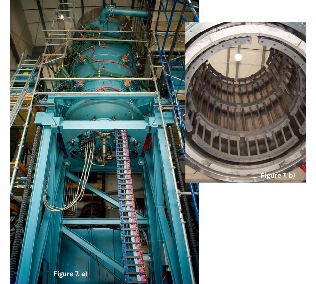
Figure 7. a) Series 3800 bottom-loading silicon carbide chemical vapor deposition furnace. b) Series 3800 chemical vapor deposition furnace hot zone with multizone control; 53″ diameter x 83″ height (1,350 mm x 2,108 mm) graphite hot zone furnace rated for 1600°C (2910°F) operation. | Image Credit: Centorr Vacuum Industries
A smaller graphitization unit was also developed in a 30″ diameter x 40″ height (76 mm x 1,000 mm) size rated to 2900°C (5250°F) maximum temperature in a vertical bottom-loading configuration for processing smaller parts in lower volumes for aerospace brakes.
The silicon carbide chemical vapor deposition units for laboratory applications discussed previously are also needed for production-size volumes (Figure 7). Due to tight temperature uniformity requirements, these units are multizone control with graphite hot zones constructed of rigid graphite board for process durability. The pumping systems can be either “dry” or “liquid ring” designs for processing the acidic off-gas materials. A post-exhaust chemical scrubber system is required to safely neutralize the hydrogen chloride off-gases.
Enabling the Next Generation of Aerospace Materials
The difficult design requirements of next-generation aerospace technologies will continue to push the existing limits of material performance. As characterization and development of new materials will be critical to the success of these aerospace programs, vacuum and controlled atmosphere furnaces will play an essential role in the production of such materials.
References
American Elements. n.d.a “Silicon Carbide Data Sheet.” https://www.americanelements.com/silicon-carbide-409-21-2.
American Elements. n.d.b “Zirconium Diboride Data Sheet.” https://www.americanelements.com/zirconium-diboride-12045-64-6.
Mesa, J. 2024. “What’s the Difference Between a Hypersonic Missile and ICBM?” Newsweek, November 21, 2024. https://www.newsweek.com/difference-between-icbm-irbm-missiles-1989780.
Smith, C. R. 2021. “Aerodynamic Heating in Hypersonic Flows.” Physics Today 74 (11): 66–67.
TomorrowDesk. 2025. “Hyperian Aerospace and the Dawn of Hypersonic Flight.” TomorrowDesk, March 29, 2025. https://tomorrowdesk.com/evolution/hyperian-aerospace-hypersonic-flight.
Heat Treat Todaythanks the American Ceramic Society for allowing us to print this piece. This article was originally published in ACerS Bulletin, September 2025.
About The Author:
Scott K. Robinson Product Manager of Ceramics and Powder Metallurgy Centorr Vacuum Industries
Scott K. Robinson is product manager of ceramics and powder metallurgy at Centorr Vacuum Industries (Nashua, NH).
If you are one of many heat treat professionals watching AM take over the industrial world with bated breath, it may be time to stop watching and start doing. This article highlights the rapid rise of AM and how changes in your heat treat operations may be needed.
This informative piece was first released inHeat Treat Today’sAugust 2025 Automotive Heat Treating print edition.
For manufacturers who produce customized or complex parts and components for the medical, aerospace, automotive, and other industries, additive manufacturing (AM) with metals has the potential to bring innovation and agility to the process.
However, because AM is a somewhat nascent technology, there are still challenges to address before it is widely accepted throughout the manufacturing industry. Fortunately, as research and development continue, the aerospace and automotive industries are beginning to acknowledge that parts made via AM are robust enough for use in safety-critical applications. Manufacturers who want to use AM to gain a competitive edge are advised to zero-in on the most suitable method for metals and determine in which applications AM presents an economically viable solution.
The Additive Manufacturing Market
AM, also known as 3D printing, is the process of creating an object based on a digital file, such as a computer-aided design (CAD) or one created with a laser scanner. Unlike traditional manufacturing methods that often involve cutting or subtracting material from a solid block (like machining), AM involves building up thin layers of material — usually metal, ceramic, or plastic — one by one using a 3D printer.
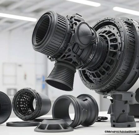
AI-generated image of 3D-printed turbine engine components
AM is increasingly transforming the manufacturing industry, enabling faster prototyping, customized production, lightweight parts, and complex shapes and geometries that would be impossible to manufacture using conventional casting, machining, or subtractive techniques, such as milling, grinding, carving or shaping.
For product design, prototyping, and reverse engineering applications, AM allows designers to rapidly print parts as a single piece, reducing material waste, saving time, and reducing costs, all while getting new products to market faster. Although the same advantages apply to traditional manufacturing applications, manufacturers have not been as quick to adopt the technology.
Still, the AM industry is seeing growth. A recent report from Grand View Research states that the global AM market size was valued at over $20 billion in 2023 and is expected to grow at a CAGR of 23.3% from 2023 to 2030, with unit shipments of 3D printers expected to reach 21.5 million units by 2030 thanks to a growing demand for prototyping applications in the healthcare, automotive, aerospace, and defense industries. The report also acknowledges that rigorous R&D in 3D printing will further contribute to growth.
Additive Manufacturing Techniques for Metals
Currently, three primary techniques are used for AM with metals: laser powder bed fusion (LPBF), directed energy deposition (DED), and binder jetting.
LPBF
LPBF technologies, including direct metal laser sintering, selective laser sintering, and direct metal printing, use a laser to sinter or fuse powdered metal particles until a complete part if formed. LPBF processes typically include heating the bed of powdered metal to a consistent temperature. The printer begins applying the first layer over a build plate, fuses the powder particles together with a high-powered laser, and then continues the process layer-by-layer until the part is finished.
After the part is printed using LPBF, it is removed from the powder bed, cut away from the build plate, heat treated to prevent internal stresses, and finally machined or polished to achieve the desired surface finish.
LPBF is limited by the size of the print bed, so it is not suitable for manufacturing large components or parts.
DED
DED using powdered metals also relies on a laser to produce metal parts. However, rather than spreading powder on a bed, the DED machine blows powdered metal out of the print head and uses a laser to fuse the part during construction.
DED-manufactured parts require post-processing heat treatment and machining steps. And while DED is a faster process than LPBF, there are a limited number of materials that can be used in the DED process, and the technique still needs more research and development before it sees widespread commercial use.
Binder Jetting
Binder jetting deposits a layer of loose metal followed by a layer of binder material layer by layer to create the product. During the process, a binder jetting machine distributes metal powder over the print bed to form an unbound layer. A jetting head then spreads a binder to adhere the powder. The machine continues to spread alternate layers of building material and binder to form a complete product. Sintering is generally required after printing to remove the binder, resulting in a part that is composed entirely of metal.
While binder jetting is a fast process and offers the opportunity to create and sinter parts in batches, it is currently a more expensive option. However, research and development into this technology, the availability of binder jets from companies (e.g., Markforged and HP), and the potential to use binder jetting for high-volume batch production may eventually make binder jetting the technology of choice for metal AM.
Post-Processing Heat Treatment for AM Parts
No matter the print technique, some AM-printed metal parts will require post-process heat treatment in which the printed part is subjected to specific temperatures and durations and then cooled to enhance or customize the properties of the metal material and optimize performance and reliability of the part.
Applying controlled heating and cooling cycles during post-printing heat treatment eliminates internal stresses created during the AM process to prevent distortion, cracking, and warping that would negatively impact part performance and reliability. Heat treating can also be used to increase hardness, density, strength, and fatigue resistance to optimize performance of the part. Furthermore, heat treating can be applied to customize the mechanical properties of the final part and provide specific characteristics so that it performs reliably in the intended application.
The type of heat treatment used following AM will depend upon the printing technique, metal material, and desired characteristics and properties. Annealing, sintering, normalizing, quenching, and tempering are commonly used. Hot isostatic pressing (HIP) — another post-process option that is used to reduce porosity and improve the density, performance, and reliability of AM-printed parts — will be specifically addressed in a subsequent article release.
Greater Acceptance in Industry Sectors
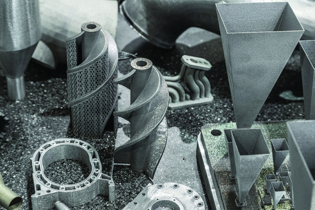
Metal alloy 3-D printed components
While AM has been widely used for prototyping and reverse engineering, adoption of the technology has been slower for the manufacture of finished parts and components. Stephen Feldbauer, director of Research and Development, with Abbott Furnace Co., suggests that the right approach to AM with metals depends upon the ability of manufacturers to refine their application. “Manufacturers should not take the ‘shotgun’ approach of ‘I can print anything,’” comments Feldbauer. “Instead, they should focus on what makes the most sense for them and specialize in those parts rather than just printing something because it’s possible.
However, because it provides significant benefits, AM does have application in the several manufacturing sectors. Advantages in using AM to produce parts include minimization of waste, time and cost efficiency, and the ability to customize parts for single-use applications or low-volume production runs.
Thanks to these benefits, AM is currently being used in the following industries:
Aerospace: functional parts, such as engine turbine blades and fuel systems
Automotive: various components, such as suspension systems, engine parts, and door panels
Defense: obsolete parts, as well as vehicle and weapon components
Medical: implants, prosthetics, and other apparatuses
And, as AM technology continues to expand, it is becoming more widely accepted and is most notably being employed to create safety-critical aerospace and automobile parts. For example, General Motors (GM) announced that it is using AM-printed seatbelt pillar adjustable guide loops in its all-electric Cadillac Celestiq, making them GM’s first safety-related AM-printed metal part.
The component is made by Azoth using Markforged metal binder jetting technology with a liquid binding agent. Following the process, the metal parts are then sintered, polished, and plated. Automotive sector acceptance of additive manufactured safety-critical parts is a tremendous boon for the AM industry.
Experts like Feldbauer see the need for manufacturers to make a few key decisions for this technology to become a reality. “For additive manufacturing to be a commercially viable solution,” he argues, “manufacturers must determine which parts they can 3D print with high levels of success and where printing is cost effective and profitable. Commercial viability is really the determining factor as to whether a part should be 3D printed or made using conventional manufacturing techniques.”
Currently, though, AM seems to be benefiting smaller jobs. According to Feldbauer, AM usually makes the most sense for small runs where there is a need for customized tooling; in these cases, manufacturers run into too complex of shapes or simply to time or cost intensive.
The Future of AM
While AM is increasingly accepted as a beneficial process across many industries, it still faces challenges affecting its usage more broadly, such as material restrictions, bed or plate sizes for techniques that rely on bed printing, and the need to purchase high-end printers from a market that is constantly consolidating. Research and development into the process, more diversity in technologies, increased availability of AM outsourcing companies, and the benefits associated with cost, time, and material reductions are expected to be a driving force in widespread commercial adoption.
Stephen Feldbauer, director of Research and Development with Abbott Furnace Co., updated Heat Treat Today on the state of AM in 2025
As the technology continues to mature, AM will continue to expand into industries where the availability of high-volume AM production, such as is possible with binder jetting, would reduce the cost of part manufacturing. Additionally, optimizing post-process heat treatment methods will help further enhance the cost effectiveness of AM with metals and enable more customized characteristics. These advances could make AM an attractive and economical option for manufacturers, so those who want a competitive edge should begin to focus and refine application of AM to the parts for which it will be most worthwhile.
References
Grand View Research. 2022. Additive Manufacturing Market Size, Share & Trends Analysis Report by Component, by Printer Type, by Technology, by Software, by Application, by Vertical, by Material, by Region, and Segment Forecasts, 2024 – 2030. April 2022. Grandview Research. Report ID: GVR-4-68039-922-9. https://www.grandviewresearch.com/industry-analysis/additive-manufacturing-market#
Check out our AM/3D Trivia to test your knowledge of the AM/3D industry, the processes, and the technology.
This editorial was written by the Heat Treat TodayEditorial Team.
In today’s Technical Tuesday installment, we highlight the various techniques and developments in the world of metal AM as it pertains to post-process heat treating. Check out the trivia quiz below to test your knowledge of the AM/3D industry, the processes, and the technology.
This feature was first released inHeat Treat Today’sJanuary 2025 Technologies To Watch in Heat Treating print edition.
Additive manufacturing (AM), commonly known as 3D printing, has a history marked by constant innovation for uses across the space, aerospace, medical, food, and manufacturing industries, to name a few. While AM is known to support, streamline, and customize part production, advanced materials paired with evolving AM techniques are creating new possibilities in materials engineering and industrial manufacturing. Due to the nature of this ever-developing technology, in-house heat treaters must continually learn about AM components and how thermal processing may enhance component properties.
Emanuel “Ely” Sachs
What was the original name for additive manufacturing (AM), circa 1980s? A) 3D printing B) Rapid prototyping (RP) C) Additive manufacturing (AM) D) Rapid tooling (RT)
What grade of stainless steel is most commonly used for AM to achieve varying levels of strength, hardness, and elongation when heat treated? A) 17-4 PH B) 316L C) 304 D) 430
Who is Emanuel “Ely” M. Sachs? A) An engineer at GE Aviation who combined multiple parts into one huge, complex design using a laser-based additive manufacturing method called direct metal laser melting B) An engineer at Stratasys Ltd., an American-Israeli manufacturer that began using a material extrusion based process with their FFF (fused filament fabrication) technology to print parts, patented in 1989 C) A professor of Mechanical and Materials Engineering at Worchester Polytechnic Institute who evaluated the post process heat treating of DMLS titanium alloy parts D) An MIT engineering professor who patented the process of metal binder jetting technique in 1993
What do cast parts made from powder metallurgy methods and AM parts have in common? A) The same heat treatment cycles produce the best results B) Custom cycles are used in less than 2% of both applications C) Parts exhibit porosity D) None of the above
What are the most commonly adjusted parameters to achieve higher yield strength when heat treating AM parts? A) Cooling and heating rate B) Temperature and time C) Time and pressure D) Temperature and pressure
Why is HIP known as the “gold standard” for processing AM parts for space? A) Eliminates porous microstructures without compromising the part’s geometries and dimensions B) High level of control and uniformity C) Combines high temperature and pressure to improve a part’s mechanical properties D) All of the above
What is NOT a potential benefit of additive manufacturing? A) Immediate cost savings B) Fast part production C) Rapid prototyping D) Opportunity for increased automation and use of robotics
What are the two main categories for most 3D printing methods? A) Those that use liquid binding polymers, and those that don’t B) Binder jetting technology (a non-melt-based process) and melt-based processes C) Both A and B D) Neither A nor B
Which alloy was originally developed for aerospace applications but became one of the most common biomedical alloys? A) Inconel 718 B) Inconel 625 C) Ti-6Al-4V D) Hastelloy C22
What was the first rapid prototyping method to produce metal parts in a single process (and is one of the most widely used AM technologies to manufacture Ti-6Al-4V parts)? A) Powder-bed fusion (PBF) B) Directed energy deposition (DED) C) Sheet lamination (SL) D) Direct metal laser sintering (DMLS)
In what way does high temperature processing — specifically HIP below the annealing temperature (1470°F/799°C) — improve DMLS Ti-6Al-4V parts? A) Preserves surface roughness and enhances osteointegration B) Reduces porosity and enhances corrosion resistance C) Both A and B D) Neither A nor B
What is the ideal way to process 3D printed parts made using liquid binder polymers? A) Print the parts in-house followed by debind and sinter. B) Have AM parts delivered in-house for heat treating when parts are at the “Green” stage C) Have AM parts delivered in-house for heat treating when parts are at the “Brown” stage D) None of the above
The thermal processing industry is a good example of how the on-site production of hydrogen by water electrolysis can be beneficial for many of its processes and for reducing the CO2 of its plants. In today’s Technical Tuesday, David Wolff, industrial sales director at Nel Hydrogen, discusses how, from plasma spray to metal AM binder jet to annealing at rolling mills, industries across medical, automotive, and beyond are looking to water electrolysis for hydrogen production.
This informative piece was first released inHeat Treat Today’sDecember 2024 Medical & Energy Heat Treat print edition.
Hydrogen atmospheres are widely used in high temperature thermal processing, including annealing, brazing, PM, MIM, and binder jet AM sintering, metal-to-glass sealing, and related processes such as thermal spray. Hydrogen helps heat treaters achieve acceptable product characteristics. It’s used as a very powerful reducing agent, and it actively cleans surfaces as compared to inert gas atmospheres which only displace oxygen.
Relative to hydrogen’s use in helping plants decarbonize, it’s a fact that major OEMs buying heat treating services and heat treated products are demanding that their suppliers report their decarbonization progress. To meet the needs, hydrogen generation is becoming ever more compelling to heat treaters to ensure hydrogen for atmosphere needs inside the plant, and to help minimize their carbon footprint.
The Clean Energy Supply Conundrum
Most U.S. heat treating facilities get their atmosphere components delivered by truck. The truck emits CO2 and the hydrogen on that truck is likely “gray” hydrogen made from natural gas. Hence, the carbon footprint from their hydrogen use is notable. Importantly, the electricity grid operators are actively seeking ways to enhance the business success of providers of low carbon electricity. The key issue with those providers — solar, wind, hydro, and nuclear — is that they cannot easily follow the ups and downs of demand. Instead, consumers get electricity from those resources when the wind is blowing, the sun is shining, or the river is high. In the case of nuclear plants, they preferentially run at near fixed output, day and night. They run continuously regardless of demand. As the grid demand is very low at night, they get very low prices for the electricity they generate. They only make money for 12 or so hours a day. That’s why a lot of nuclear plants are threatening shutting down for economic reasons.
Taking Advantage of Low Demand Period Energy Prices for Use During High Demand Hours
Consider this scenario: What if a client with electrolysis capacity to produce hydrogen, such as a heat treater, could buy electricity at lower nighttime prices to make the hydrogen it needs during the day shift for its various processes, perhaps even heating their furnaces? The clean energy provider would be pleased to have more income during its low demand, low price times. The heat treat plant is happy saving money buying decarbonized electricity at low demand prices to make clean hydrogen for its various thermal processes and to operate its furnaces. And, the heat treat company’s OEM clients demanding decarbonization are satisfied, too.
How To Get Started
The scenario described above is a practical and real one for the heat treat industry today. Nel Hydrogen recommends that a heat treat company begin with a plan. That plan may comprise several phases. It’s important to seek out a knowledgeable hydrogen partner in this endeavor to specify exactly what’s needed. For heat treat applications, users generally would want compact equipment, extreme hydrogen purity, load following, near-instant on and instant off, and sufficient hydrogen pressure that make it flexibly suited for a variety of thermal processes, and for hydrogen storage addition at a later time if desired.
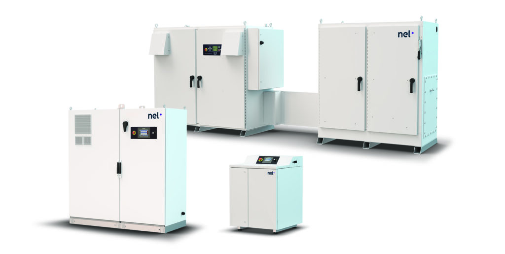
Figure 1. Compact hydrogen generators using water electrolysis for thermal processing applications (Source: Nel Hydrogen)
Both batch and continuous processes can be served. Batch processes may benefit from a small amount of surge storage at the outset. By combining on-site hydrogen generation with a small amount of in process hydrogen surge storage if needed, on-site hydrogen generation can be used to meet the needs of batch processes such as batch furnaces and thermal spray. By carefully choosing generation rate and pressure, and surge storage vessel volume and pressure capacity, the combination of generation with surge storage can provide maximum process flexibility while minimizing the amount of hydrogen actually stored.
The presence of a small amount of hydrogen surge storage also protects clients’ parts in case of an electric interruption that stops hydrogen production. The surge storage hydrogen can protect the parts while they cool under a reducing atmosphere.
In practice, specific client priorities such as minimum hydrogen storage, or lowest system capital cost, or highest degree of expandability, or least amount of space occupied, can be met by choosing the specific hydrogen generator capacity and surge storage system employed for any particular production challenge.
Examples of Thermal Processors Producing Hydrogen On Site with Water Electrolysis
Decarbonization will be a near-future requirement as part of the global effort to evolve towards a cleaner, greener world. On-site hydrogen generation in industry makes great sense to align with those initiatives. Right now, the thermal processing industry is experiencing the benefits of producing hydrogen on site for its production processes, and the decarbonization demand will be easier to accommodate with that infrastructure in place.
Here are a few examples of companies performing a variety of thermal processes that have made the decision to use water electrolysis to produce hydrogen on site:
Plasma Spray of Cast Iron Cylinder Liners
One of the most compelling examples has been implemented by two different U.S. automakers to accommodate the increasing use of low-weight aluminum engine blocks in today’s high efficiency vehicles. Aluminum blocks must have a cast iron lining on the inside of the cylinder bore to maximize the durability of the engine. (Older readers may recall the notorious Chevy Vega that used an aluminum engine without a cast iron liner. The author’s wife had one Vega which burned through three engines!)
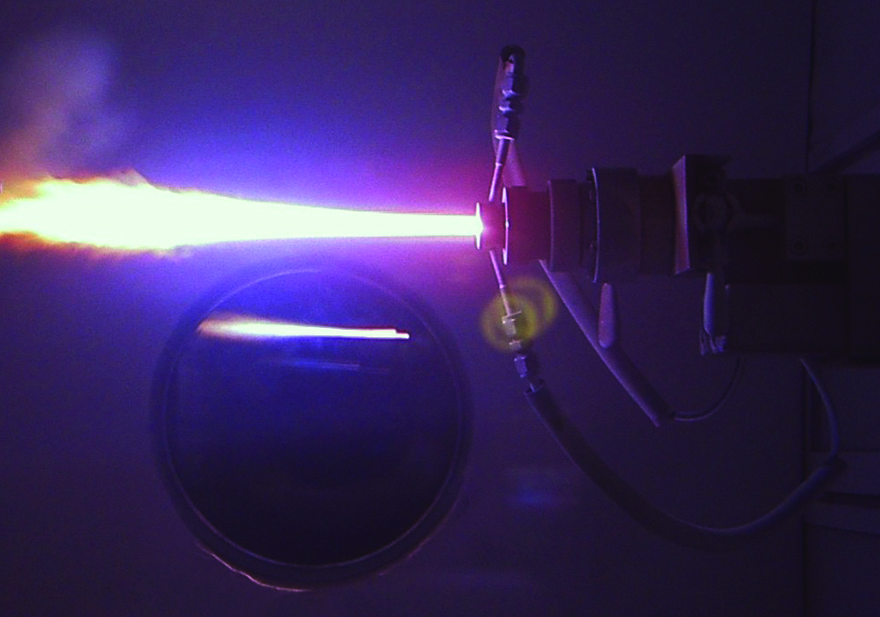
Figure 2. Plasma torch used to spray-apply metal coatings in additive
manufacturing processes (Source: Shutterstock)
The traditional approach to provide a cast iron liner was to drive a sleeve into the aluminum engine block. However, a new technology has been commercialized by which the cast iron liner is spray-applied using a plasma torch. The torch uses hydrogen and argon gases to add energy and maintain the necessary low oxygen atmosphere. The plasma spray was a new addition to engine production facilities that had not previously been equipped with hydrogen supply and thus elected to generate their own to minimize delivered hydrogen and avoid the need for hydrogen inventory and extensive supply piping.
The electrolyzers recommended for plasma spray applications are compact and produce high purity hydrogen of better than UHP grade at 200+ psig pressure, with less hydrogen stored than would fill a party balloon bouquet. About the size of a washing machine or refrigerator, depending on the model, each unit is low maintenance, compact, quiet, and can be installed nearly anywhere in a facility.
Metal Additive Manufacturing (AM) Binder Jet
One of the most exciting approaches to metal AM is the technology called binder jet, which creates a near net shape part using polymer and wax binders to adhere metal powders. After the part is formed, the binders are chemically or thermally removed. Then the part is sintered to attain near net shape and full part density. Hydrogen is required for the sintering atmosphere to prevent oxidation of the part during the sintering process. Binder jet technology promises to provide for mass production of individually customized parts at high production rates and consequently lower costs than parts produced individually.
Figure 3. Binder jet metal AM parts sintered in a hydrogen atmosphere (Source: Shuttershock)
Many new metal AM production facilities are being established in factories that are not already equipped for the delivery, storage, and internal piping/distribution of hydrogen. As such, many have chosen instead to use zero inventory hydrogen made on site to minimize infrastructure investments. Electrolyzers for small-scale applications requiring up to 230 scf/hr of hydrogen gas at 99.999+ % purity are advised for metal AM. About the size of a large refrigerator, the units require minimal facility floor space, are easy to maintain, and can be installed in any non-classified space. Applications for AM include medical, electronics, industrial, and automotive components.
Annealing at Rolling Mills
Plate and strip metal are processed in rolling mills where the thickness of the metal is reduced by alternating “cold” rolling steps followed by intermediary hot annealing steps. Cold rolling makes the metal more brittle, so it is necessary to have an annealing step following each rolling step. The metal is alternately thinned and then softened for what could be several iterations. Hydrogen is required for the annealing steps to maintain metal surface quality while heated. Because of the periodic market disruptions in delivered hydrogen from plant outages or trucking interruptions, several rolling mills have chosen to generate hydrogen on site to augment or entirely replace their delivered hydrogen supply. The benefits that the plants experience are primarily focused on supply reliability. Of course, they are also eliminating the carbon footprint associated with truck delivery. In this case, the carbon footprint of the generated hydrogen is determined by the particular electricity generating mix that serves the plant site.
Most often at rolling mills, electrolyzers that produce up to 1,140 scf of hydrogen gas at 99.999+ % purity are best suited for the hydrogen requirement. These units replace the need for hydrogen tube trailers or liquid hydrogen storage. They can be installed in the mill or can be containerized outdoors, offering flexible siting and reduced operational safety risks compared to delivered hydrogen.
Figure 4. Steel rolls are heated in an annealing step to soften the metal during production. (Source: Istock)
On Track Towards Decarbonization
Described in the examples above, once the means to generate hydrogen is chosen at a thermal processing facility, the company can move further along the decarbonization journey. This may be to apply a strategy as outlined in the electricity scenario whereby the company takes advantage of low demand rates or institutes an alternative creative idea. Certainly, as more and more clients demand proof that suppliers are reducing their carbon footprint, more strategies will be developed and implemented to serve the thermal processing industry. Simply generating hydrogen on site removes the trucking emissions factor and is a beneficial and practical starting point.
About the Author:
David Wolff Eastern Regional Sales Manager Nel Hydrogen
David Wolff has 45 years of project engineering, industrial gas generation and application engineering, marketing and sales experience. He has been at Nel Hydrogen for over 25 years as a sales and marketing leader for hydrogen generation technologies.
For more information: Nel Hydrogen at sales@nelhydrogen.com.
The automotive industry is going electric — electric vehicles are a popular choice for consumers. To continue sustainable efforts for a healthier planet, heat treaters need to seriously consider energy recovery technologies for their equipment and processes. In this Technical Tuesday article, Harb Nayar, founder, president, and CEO at TAT Technologies, examines the use of combustible burner technology (CBT), specifically CBT technology retrofitted on conveyor furnaces that utilize some level of combustible produced by synthetic or generated atmospheres, and that have peak temperatures above 1400ºF (760ºC).
This informative piece was first released in Heat Treat Today’s August 2024 Automotive print edition.
The reality is that rather than just neutralize these emissions, heat treaters can use them to heat their parts, even before preheating. The focus of this article is to examine the use of combustible burner technology (CBT) and more specifically, CBT technology retrofitted on conveyor furnaces for processes that has the following:
Here’s a 20-second video of “dancing” flames exiting a conveyor furnace that is sintering PM parts in a N2-H2 atmosphere at 2050°F (1,000+ lb./hr.). Source: TAT Technologies
Recovering Latent Heat Energy
A typical conveyor furnace found on the shop floor has three distinct zones, a preheat zone, a high heat zone, and a cooling zone. Since it is desirable in these units to have a forward atmosphere flow (toward the entrance end of the furnace and opposite the direction of part travel), combustibles emitted while processing the parts exit at the entrance and are typically burned off before entering the room or exhaust system. Often, flames can be seen burning at the front of the furnace.
PM processing is very specific and often more difficult to adopt compared to other continuous atmosphere furnaces. Given the large percentage of PM parts used by the automotive industry, it offers a good example of how heat treaters can achieve energy and cost savings via energy recovery technology.
A Close Look at the Process
Sintering is commonly performed in continuous atmosphere furnaces. In the sintering process, powder metal is combined with a binder, often solid wax (Acrawax®) or stearate-based lubricants are used in the compaction process to make green parts. Delubrication (aka delube, debindering) then takes place in the preheat section of the furnace. There are three phases during PM sintering:
Typical door-to-door time varies between one to five hours, depending upon the material being sintered.
The most common atmosphere used in sintering processes is N2 with 7–20% H2. In other shops, the atmosphere used is Endothermic gas, which has (approximately) 40% H2, 20% CO, with the balance primarily N2 or dissociated ammonia (DA) with a composition of 75% H2 and 25% N2. In some sintering operations, a mixture of DA and N2 is used.
The atmosphere with all the combustibles travels from the high heat section to the preheat section and finally exits from the front of the furnace where the various pollutants are burned off before entering the exhaust system. The total amount of combustibles varies between 10% and 50% depending on the type of atmosphere and material being sintered.
For example, CBT units have been installed for the delubing of tungsten-based alloy parts prior to sintering in high temperature pusher furnaces.
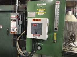
Figure 3. CBT unit called “LBT-I.” (Left) main body before installation and (right) control panel. Source: TAT Technologies
CO: approximately 0.12 KW per cubic foot of CO or 0.4 KW per cubic meter of CO
Wax lubricant: approximately 5 KW per lb. or 11 KW per kg of lubricant going into the furnace
How CBT Works
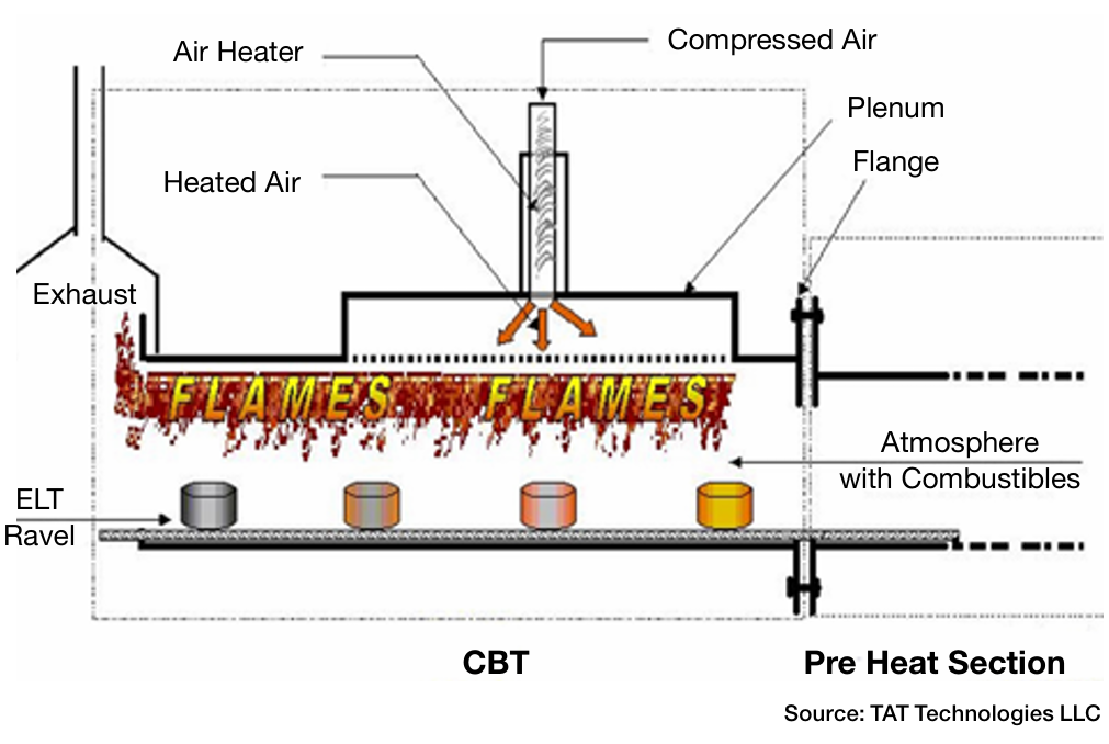
The CBT unit retrofits to the flange of the preheat muffle of the sintering furnace. In its reaction chamber, the furnace atmosphere gases enter from the heating sections carrying the various combustibles. These are circulated in the chamber in which preheated air at 1000–1600°F is introduced through vents in the roof of the chamber (Figure 1).
When the furnace atmosphere and air mix, a combustion reaction takes place with flames being produced over the incoming load of parts that are traveling on the belt towards the preheat section. Heat from theses flames helps vaporize the lubricant and any oils present at a high rate. The lubricant vapors flowing out of the parts are instantly and continuously consumed within the CBT chamber before leaving to enter the exhaust system in the front of the furnace. However, the energy released from the burning lubricants and oil vapors remains, adding to the energy from combustion within the CBT chamber. Enough total heat is generated to heat the parts and the belt to temperature above 930ºF (500ºC) before entering the preheat section. This “recovered” heat energy is essentially free as it is generated from the combustibles and lubricant and oils (e.g., H2 for oxide reduction and lubricant for ease of compaction).
Figure 4. Illustration of the energy generated within the CBT reaction chamber. Parts are moving from right to left. Source: TAT Technologies
Another Case Study Illustration
Energy recovery in a CBT reaction chamber from fully combusting H2 coming from the preheat section of the furnace at a flowrate of 400 CFH (11.3 m3/h) and lubricant coming with the green parts at a rate of 7.2 lbs (3.3 kg) per hour is approximately 235,000 Btu/hr (248 MJ/hr) which is equivalent to an energy savings of approximately 70 KWh of electricity.
Additional Heat Treat Applications
Many other heat treating processes benefit from CBT technology. Some examples follow next.
Annealing often utilizes continuous furnaces.
The percentage of H2 in the atmosphere is generally much higher — in some cases 100%.
Materials and annealing practices vary from plant to plant.
Prior to annealing, the material often has surface oxidation and/or some type of coating (e.g., oils, dry lubricants).
The goal is to avoid decarburization and produce an acceptable microstructure, which highly depends on the time/temperature cycle.
Brazing is another thermal process that benefits from CBT technology.
Brazing of most automotive parts is done in either in Exothermic or Endothermic gas or N2-H2 or H2-Ar atmospheres.
Materials being brazed are typically low carbon steels or stainless steels. In some instances, other special materials are used.
The goal is to have clean, oxide, and soot-free joint surfaces just before the filler metal (commonly copper or nickel-based alloys) melts, flows into the gap between the parts by capillary action, and solidifies producing a homogeneous part.
Summary
Figure 5. Photo shows the main body of a CBT unit. Different product models vary in length and flow capacity, but all produce improvements in product throughput up to 25–50%. Source: TAT Technologies
Increased productivity. The technology increases throughput up to 50% depending upon the model used since incoming parts are heated prior to entering the preheat section of the furnace.
Energy savings. The power requirements in the preheat section are reduced and throughput increases up to 50% depending upon the model used.
Improved heat transfer. Parts can be heated to a higher temperature in a shorter amount of time for faster removal of organic materials prior to subsequent reduction of metal oxides.
Decreased unit cost. The energy consumption is lowered and overall cost of parts produced in reduced.
Environmental benefits. Ambient temperature in the front-loading area by 10–30°F is lowered since the burn off flames are significantly smaller. Processes being run are less sensitive to air infiltration in the vicinity of the furnaces.
About the Author:
Herb Nayar President & CEO TAT Technologies Source: TAT Technologies
Harb is an inquisitive learner and dynamic entrepreneur who will share his current interests in the powder metal industry, and what he anticipates for the future of the industry, especially where it bisects with heat treating.
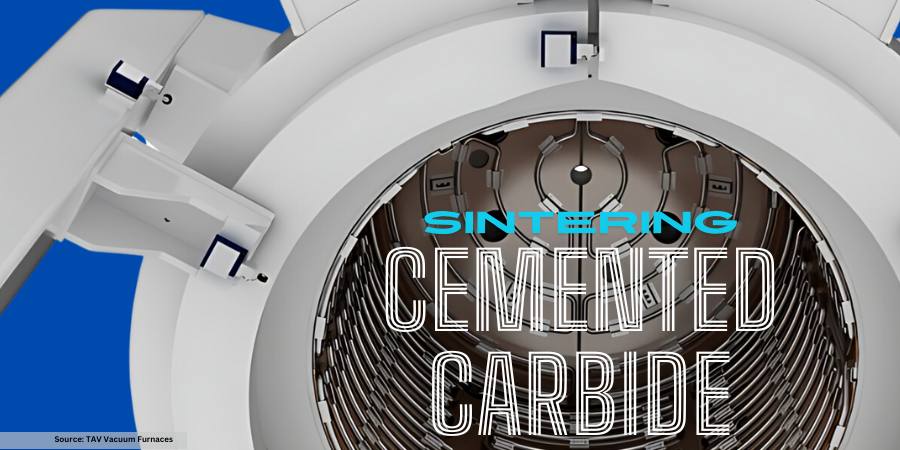
When processing cemented carbide, there are a few considerations you need to understand to use the proper sintering equipment. One of the biggest factors is the actual material; what is the colbalt content level of the processed material?
In this best of the web article, walk through the steps of dewaxing, sintering for appropriate densification, and the processing temperatures that are required for sintering cemented carbide.
An Excerpt:
“Other than mechanical stresses due to the differential pressure between inside and ambient pressure outside the furnace, operating at relatively high temperatures with high pressure of gas would lead to significant dissipations of heat to the external environment. This is not only anti-economic from an efficiency point of view, but could also compromise the structural integrity of the water-cooled steel vessel of the furnace by overheating it.”
The amazing materials that are produced through additive manufacturing (AM) and 3D machining often require post-processing heat treatments before these become final components that launch into space. What are the trends of AM/3D outside our planet, and what technical resources are available to you as you make one step into this field? This original content piece from the Heat Treat Today editors will help you understand where technology stands in 2024.
Why Does AM/3D Go to Space?
Contact us with your Reader Feedback!
A broad spectrum of industries have found the appeal of additively manufactured parts, industries ranging from mining to medical and automotive to space. Much of this has to do with complexity of components that new engineering techniques require, the desire to save on material costs, and the ability to condense lead time. For some, additive manufacturing is becoming essential to the space industry; as Tobias Brune, head of the Business Unit Additive Manufacturing at TRUMPF, has commented, “With our 3D printing technology, we are driving the commercialization of the space-travel industry. If you want to be successful in the space-travel industry today, you have to use additive manufacturing.”
When should you expect this transition? Now.
In January of this year (2024), the first metal 3D printer for space was launched to the Columbus module of the International Space Station (ISS). This is a very active, integrated sense of seeing AM in the aerospace industry, and test runs with this equipment will ensue.
Flight model of 3D Metal Printer Launched on NG-20 Source: ESA
The Exploration Company in Europe plans to use 3D printers from TRUMPF (laser specialist) to print core components in engines for spacecrafts. The intent: missions in Earth’s orbit and to the moon.
Heat Treat & thermal Processing Requirements of Post-ProcessingAM
If you are going to get involved in AM, it is essential to have the right equipment. One of the most talked about equipment is hot isostatic pressing (HIP) technology. Often, heat treat operations use HIP equipment for post-process heat treating in order to get the solid part they desire. For the most part, commercial heat treaters have positioned themselves to handle the R&D required to navigate the terrain of overcoming processing challenges of new/complex parts and creating standardizations. However, privateR&D facilities and departments are also building out their capabilities to handle AM in HIP.
However, so also have vacuum furnaces been a key leader in heat treating AM components. Here, commercial heat treaters have also made moves to expand their equipment/process offerings to accommodate AM parts.
So also do atmosphere considerations need to be considered, withgasses like H2 competing trying to capture the limelight.
Continue the Exploration: AM/3D Articles for Space
Looking for an introduction to the AM/3D topic for heat treaters? Begin with this article by Animesh Bose, an engineering pioneer: “The Role Of Heat Treat in Binder Jetting AM for Metals.” The article uncovers the history of one of the most important types of AM/3D manufacturing — binder jetting AM.
Then, take a step over for an industry focus on what “heat treatments for space” look like. Mike Grande eloquently summarized the current processes needed in space in this editorial from the March 2024 Aerospace print edition. Read “The Role of Heat Treatment in Space Exploration” in the digital edition of the magazine.
In-house or commercial? This article presents critical considerations of space components — with a particular emphasis on the importance of AM/3D — when considering how to grow your processing expertise and capabilities. Several examples from the frontlines of R&D are presented by Noel Brady in his article. Read the editorial, “Thermal Processing for Space and Additive Manufacturing,” for excellent illustrations.
Finally, hone in on the topic with a case study about developments in HIP technology for space component post-processing. This article begins with context confronting issues of structural integrity, especially of complex space components, with HIP. Andrew Cassese gets to the case study towards the end of his article, “High Pressure Prepares Parts for Space.”
Find Heat Treating Products And Services When You Search On Heat Treat Buyers Guide.Com