IN 718 Part 2: Heat Treatment
Today’s Technical Tuesday highlights the second installment in a multi-part series by Nikolai Alexander and The Heat Treat Doctor® Daniel H. Herring, diving into the controlled heat treatment strategies required to unlock IN 718’s exceptional high-temperature strength, toughness, and corrosion resistance. From solution annealing and duplex aging to hot isostatic pressing and additive manufacturing considerations, the authors explore how precise process control and equipment selection directly shape microstructure and performance in critical applications.
This informative piece is from Heat Treat Today’s March 2026 Annual Aerospace Heat Treating print edition. For part 1 on the history, production, and general applications, read Heat Treat Today’s February 2026 Annual Air & Atmosphere Heat Treating print edition.
Introduction
IN 718 was developed for and is extensively used in the aerospace industry. Today, the superalloy and its modifications are heavily relied upon, including IN 718Plus® (US Patent No. 6.730.264 B2), which is designed for operating service temperature to 705°C (1300°F), approximately 55°C (100°F) above that of IN 718. (IN 718Plus will be the subject of a future article by the authors). This article reviews the heat treatment of IN 718 and the need to control both equipment and process variability. Also discussed is the method of additive manufacturing (AM) to produce component parts and the heat treat challenges it poses, including the need to HIP (hot isostatically press) the material to achieve maximum property benefits.
Heat Treatment of IN 718
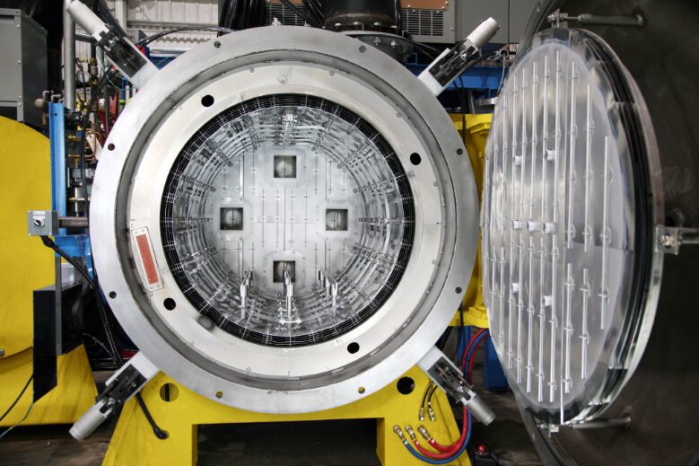
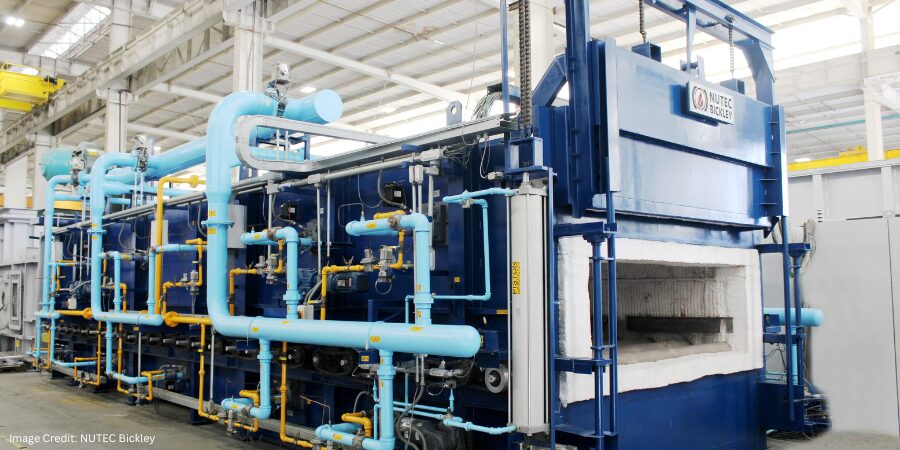
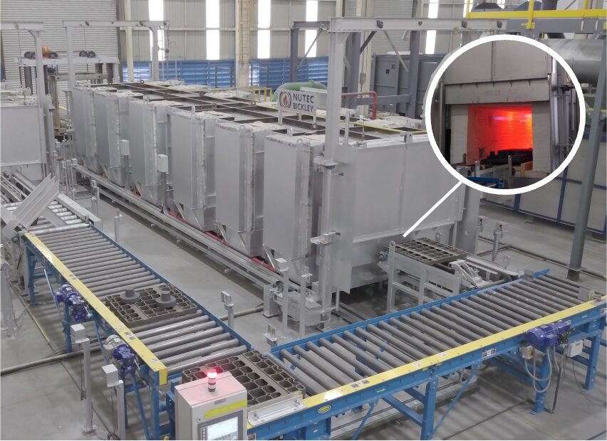
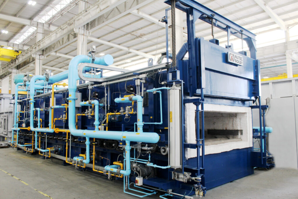
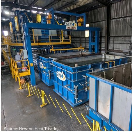
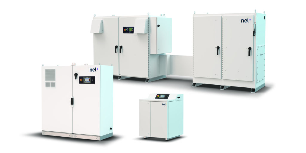
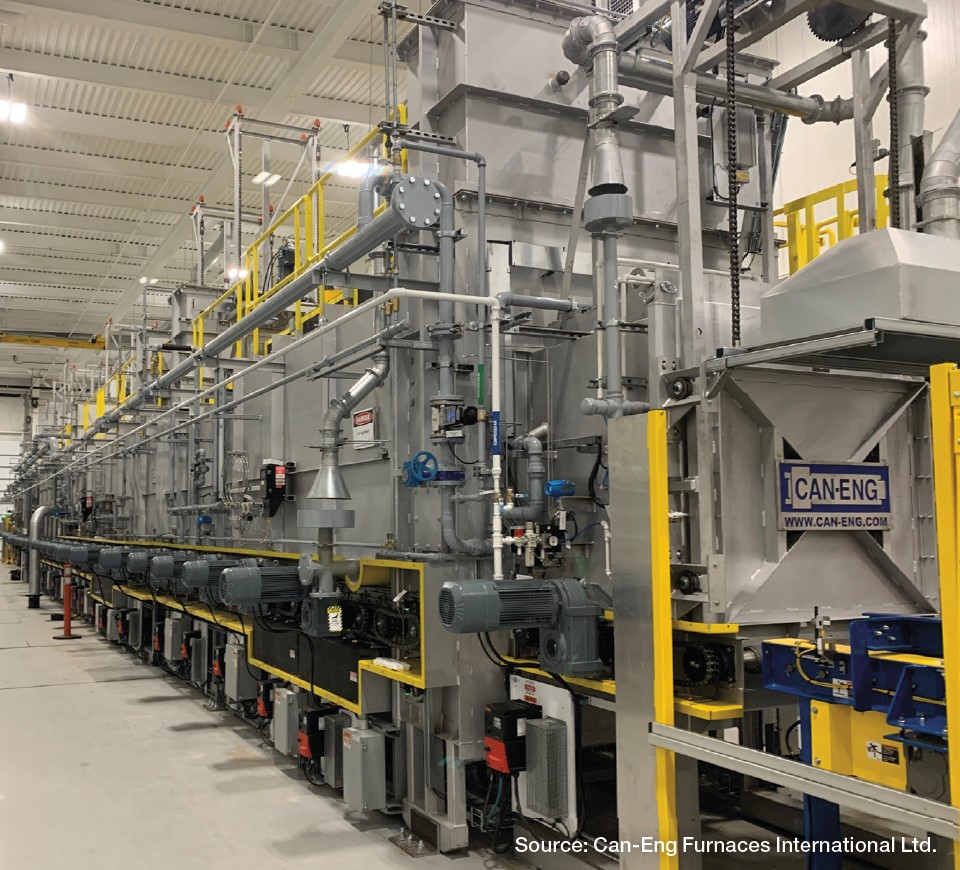
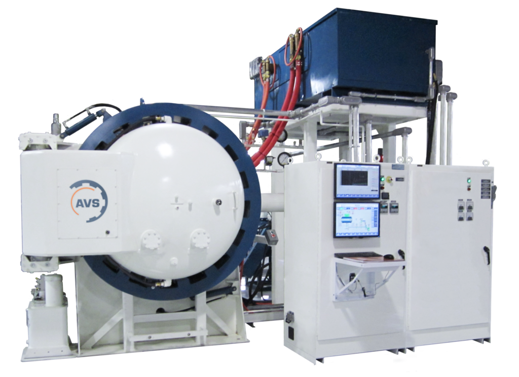
IN 718 is typically heat treated in a vacuum furnace given that it is a sensitive alloy and easily oxidized. Processing in an all-metal shielded furnace (Figure 1) offers advantages for keeping the parts bright after the aging process, without the need to wrap them.
Graphite-lined vacuum furnaces, often with molybdenum heating elements, can also be used provided appropriate precautions are taken. The furnace must be extremely leak tight with a rate of rise under 5 microns Hg per hour. Processing in vacuum is typically done in the 10⁻⁵ torr range. Argon as a partial pressure or cooling gas is necessary to avoid nitriding or oxidation. An alternative, albeit older technology, approach is the use of a vacuum-purged argon atmosphere box furnace with a retort.
From a metallurgical perspective, the amount, morphology, and distribution of the delta (δ) phase have a great influence on the properties of IN 718. During heat treatment, delta phase is extremely important for optimizing mechanical properties, particularly at high temperatures to control migration and precipitation in IN 718. The delta phase inhibits grain growth (by pinning the grain boundaries) and enhances creep and fatigue performance. However, excessive or poorly controlled precipitation is detrimental to other properties like ductility and fracture toughness.
Optimization of delta phase distribution includes selecting the proper solutionizing temperature, between 980–1040°C (1800–1900°F) depending primarily on nickel content, where the delta phase is stable (and thus precipitates out). Thermomechanical working can also achieve this effect by forming more globular-shaped particles rather than acicular (needle-like) ones (Guan, et al. 2023).
There are a number of heat treatments that can be performed on IN 718, including stress relief, homogenizing, solution annealing, precipitation hardening (aka aging), and HIP.
Stress Relief
Stress relief is typically performed at the mill and is a compromise between the amount of residual stress one would like to remove and the possibly harmful effects to both high temperature properties and corrosion resistance. For wrought alloys, stress relief at full annealing temperature is recommended since intermediate temperatures might cause aging. Hold times are one hour per inch of section thickness. For castings, stress relief is especially important when dealing with complex shapes, which may be prone to cracking in subsequent operations or when dimensional control is important.
Homogenization
Homogenization heat treatment is applied to IN 718 for the uniform distribution of alloying elements and dissolution of detrimental phases after its processing through casting and additive manufacturing (AM) routes. There is a definite relationship between laves phase fraction (i.e., the brittle intermetallic compound formed due to niobium segregation during solidification) and homogenization time at various temperatures 1140–1170°C (2085–2140°F). With an increase in homogenization temperature, the time required for dissolution of laves phase and reduction in laves phase fraction reduces drastically. Also, at a given temperature the reduction in laves phase fraction has been shown to occur with the increase of time (Eliasen and Somers 2010).
Full Annealing
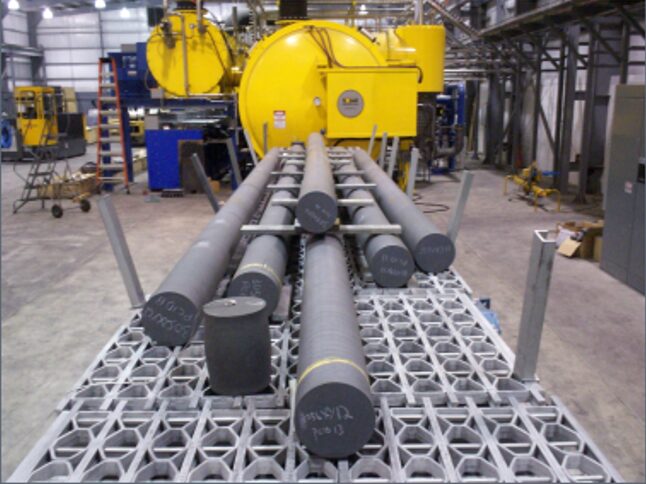
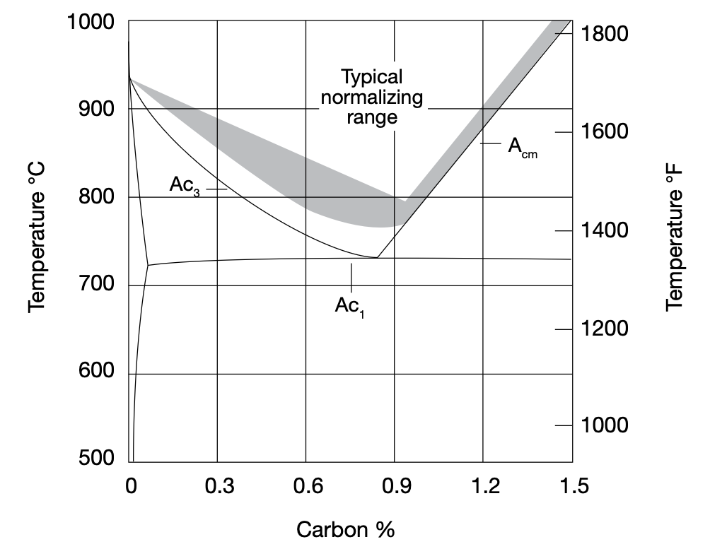
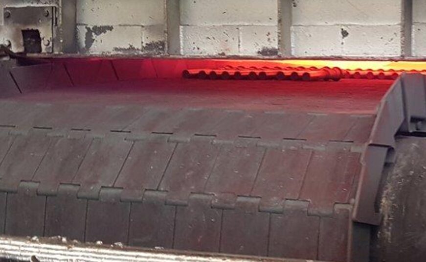
The process of full annealing involves complete recrystallization and dilution of all or most of the secondary phases to reach maximum softness (Figure 2).
The process is typically run at 955°C (1750°F) holding one hour per inch of cross-sectional area. If welding is to be performed on the component, annealing should be performed immediately after the welding operation. It is noteworthy that niobium additions help overcome cracking problems during welding.
Solution Annealing
Solution annealing (aka solution heat treating) is designed to dissolve secondary phases to prepare the alloy for age hardening and produce maximum corrosion resistance. An added benefit is homogenization of the microstructure.
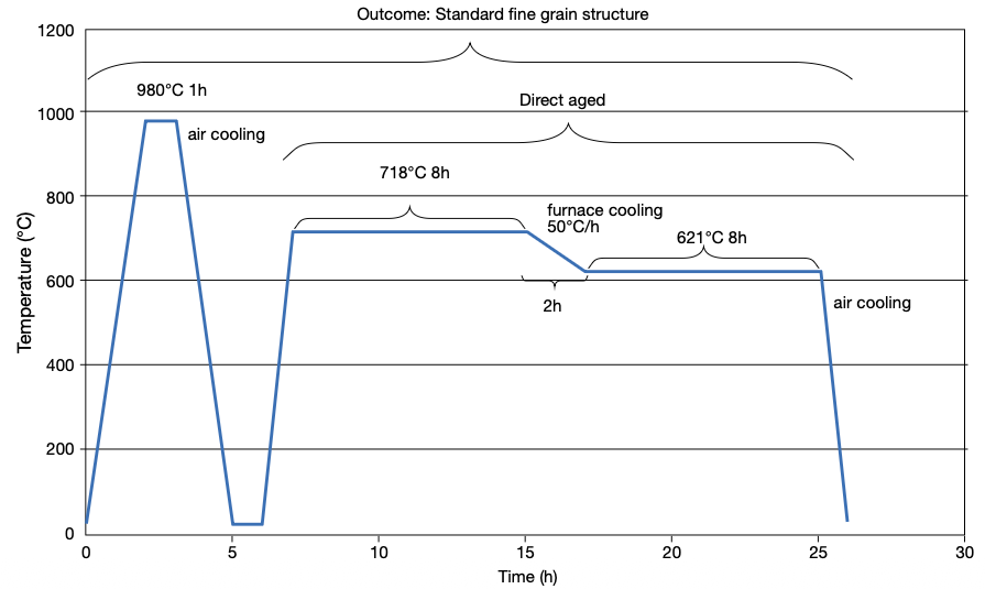
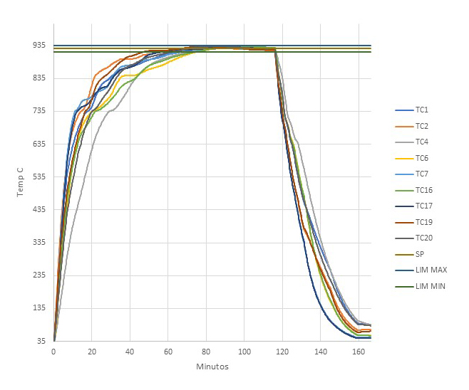
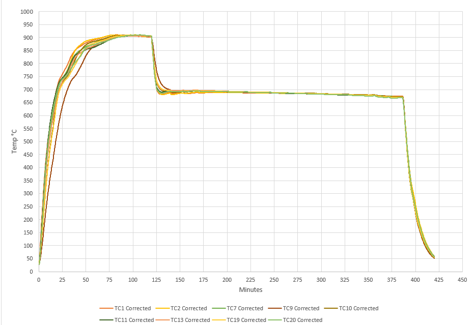
A typical heat treatment of IN 718 involves a two-step process — solution heat treating and then age hardening — to control the mechanical property response of the material (Figure 3).
For bar stock, a typical cycle might involve solution annealing at 955°C (1750°F) followed by a 2-bar quench under argon or nitrogen (which can be used if post machining will be performed). This is followed by duplex aging at 730°C (1350°F) for eight hours followed by a vacuum or rapid cool to avoid surface reactions (such as oxidation) and (depending on whether further precipitation is needed) to 650°C (1150°F) and another hold for eight hours followed by a gas fan quench.
Solution annealing at 925–1010°C (1700–1850°F) with its corresponding aging treatment is considered the optimum heat treatment for IN 718, where a combination of rupture life, notch rupture life, and rupture ductility is of greatest concern. The highest room-temperature tensile and yield strengths are also associated with this treatment. In addition, because of the fine grain developed, it produces the highest fatigue strength (Herring 2019).
By contrast, solution annealing at 1040–1065°C (1900–1950°F) with its corresponding aging treatment is the treatment preferred in tensile-limited applications because it produces the best transverse ductility in heavy sections, impact strength, and low-temperature notch tensile strength. However, this treatment tends to produce notch brittleness in stress rupture (Herring 2019).
Aging/Duplex Aging
The aging process is designed to strengthen the material, forming precipitates from the supersaturated solid solution mastic from the solution annealing step.
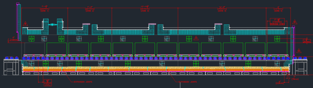
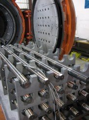
Duplex aging (Figure 4) involves a two-step heat treatment process and on IN 718 is performed around 730°C (1350°F) for eight hours followed by a vacuum cool or in some cases a rapid cool to avoid surface reactions (such as oxidation) and (depending on whether further precipitation is needed) down to 620°C (1150°F) and another hold for eight hours. This is followed by a gas fan quench. The first soak temperature is intended to initiate precipitation of phases influencing strength and hardness properties. The second soak temperature further refines the microstructure and optimizes the material’s properties based on the phases developed in the initial aging and cooling stages.
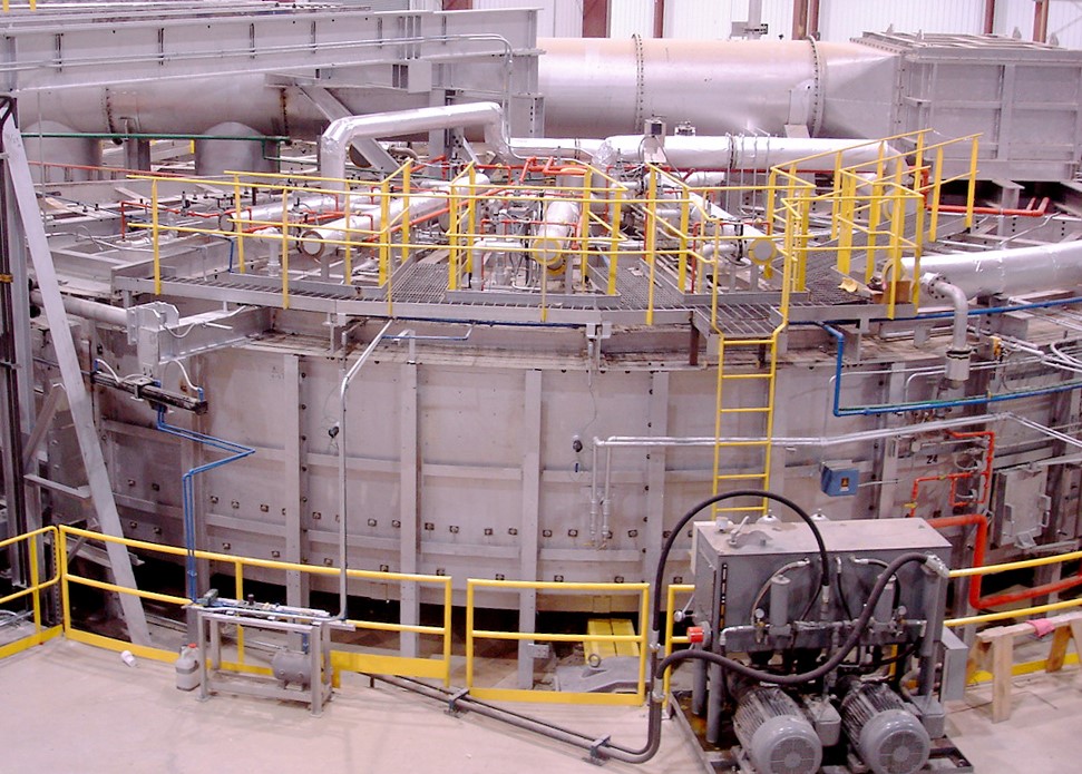
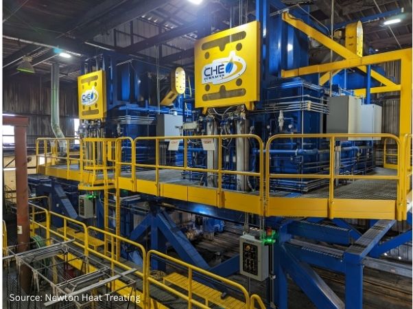
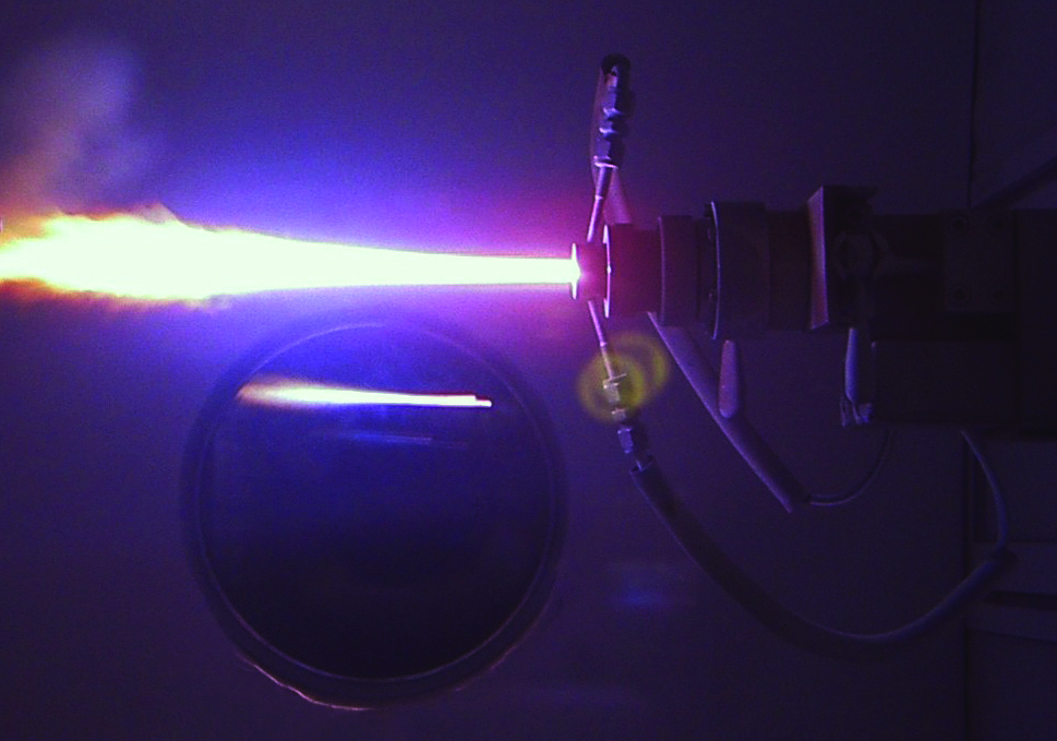
Hot Isostatic Pressing
Hot isostatic pressing (HIP) combines high pressure and high temperature to influence the density and microstructure of IN 718 (Figure 5). It is critically important to improve the mechanical strength of shape cast and additive manufactured components to homogenize the as-built microstructure and minimize variation in mechanical properties. It helps to eliminate residual stresses, close pores, close cracks and ensures the material is properly fused (Shipley 2023).
For example, it has been reported (Lee, et al. 2006) that four hours at 2155°F (1180°C) under a pressure of 25.5 ksi (175 MPa) is optimal to improve the microstructure (grain size and segregation) along with tensile properties of IN 718 castings.
Future Outlook
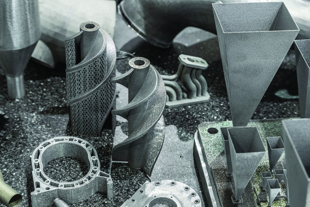
Additive manufacturing (AM) of IN 718 (and superalloys in general) is becoming an increasingly important method for component part manufacturing. It allows complex 3D shapes to be formed without the difficulties inherent in casting, forming, and machining of these alloys.
Electron beam-powder bed fusion (E-PBF) and laser-beam powder bed fusion (L-PBF) have shown great promise for processing IN 718 and other nickel-based superalloys. An absolutely necessary, if not critical, step in the process is post-HIP to heal cracks and homogenize the microstructure.
Heat treating will continue to play an important role in enhancing the properties of IN 718. It will be necessary to update the standard heat treatment requirements (e.g., AMS5662 and AMS5663) to incorporate powder metallurgy (PM) and AM technologies to optimize properties for components made by these methods.
More investigation is needed to optimize solutionizing and aging temperatures for modified IN 718 chemistries. For example, the effect of the cooling rate after aging treatments on the precipitate size and morphology and subsequent mechanical properties of the alloy must be explored in more detail (Eliasen and Somers 2010). And from a heat treatment perspective there is interest in case hardening (nitriding, low-temperature carburizing) of IN 718 (Sharghi-Moshtaghin, et al. 2010, Eliasen and Somers 2010).
Finally, AM processes rely on layer-upon-layer melting. As such, modeling, sensor technology, process temperature monitoring and control of surface displacement improve the build. Emerging trends suggest that the integration of machine learning and artificial intelligence for real-time quality control and process optimization will be a key part of the manufacturing strategy moving forward (Babu, et al. 2018).
References
Akca, Enes, and Gursel, Ali. 2015. “A Review on Superalloys and IN718 Nickel-Based INCONEL Superalloy.” Periodicals of Engineering and Natural Sciences 3 (1): 15–27.
ASM International. 2016. ASM Handbook, Volume 4E: Heat Treating of Nonferrous Alloys. ASM International.
Babu, S. S., N. Raghavan, J. Raplee, S. J. Foster, C. Frederick, M. Haines, R. Dinwiddie, M. K. Kirka, A. Plotkowski, Y. Lee, and R. R. Dehoff. 2018. “Additive Manufacturing of Nickel Superalloys: Opportunities for Innovation and Challenges Related to Qualification.” The Minerals, Metals & Materials Society and ASM International: 3764–3780.
Bradley, Elihu F., ed. 1988. Superalloys: A Technical Guide. ASM International.
del Bosque, Antonio, Fernández-Arias, Pablo, and Vergara, Diego. 2025. “Advances in the Additive Manufacturing of Superalloys.” Journal of Manufacturing and Materials Processing 9 (215): 1–31.
Chandler, Harry, ed. 1996. Heat Treater’s Guide: Practices and Procedures for Nonferrous Alloys. ASM International.
Croft Systems. n.d. “The Difference between a Wellhead & Christmas Tree.” https://www.croftsystems.net/oil-gas-blog/the-difference-between-a-wellhead-christmas-tree/.
Decker, R. F. 2006. “The Evolution of Wrought Age-Hardenable Superalloy.” Journal of The Minerals, Metals & Materials Society, September: 32–36.
Eliasen, K. M., T. L. Christiansen, and M. A. J. Somers. 2010. “Low-Temperature Gaseous Nitriding of Ni-Based Superalloys.” Surface Engineering 26 (4): 248–255.
Guan, Hao, Wenxiang Jiang, Junxia Lu, Yuefie Zhang, and Ze Zhang. 2023. “Precipitation of δ Phase in Inconel 718 Superalloy: The Role of Grain Boundary and Plastic Deformation.” Materials Today Communications 36 (August).
Herring, Daniel H. 2011. “Stress Corrosion Cracking.” Industrial Heating, October: 22–24.
Herring, Daniel H. 2012. Vacuum Heat Treating: Principles, Practices, Applications. BNP Media II, LLC.
Herring, Daniel H. 2019. “The Heat Treatment of Inconel 718.” Industrial Heating, June: 12–14.
Lee, Gang Ho, Ang Ho, Minha Park, Byoungkoo Kim, Jong Bae Jeon, Sanghoon Noh, and Byung Jun Kim. 2023. “Evaluation of Precipitation Phase and Mechanical Properties According to Aging Heat Treatment Temperature of Inconel 718.” Journal of Materials Research and Technology 27 (Nov–Dec): 4157–4168. https://doi.org/10.1016/j.jmrt.2023.10.196.
Lee, Shin-Chin, Shih-Hsien Chang, Tzu-Piao Tang, Hsin-Hung Ho, and Jhewn-Kuang Chen. 2006. “Improvements in the Microstructure and Tensile Properties of Inconel 718 Superalloy by HIP Treatment.” Materials Transactions 47 (11): 2877–2881.
Loria, Edward A. 1988. “The Status and Prospects of Alloy 718.” Journal of Materials, July: 36–41.
Polasani, Ajay, and Vikram V. Dabhade. 2024. “Heat Treatments of Inconel 718 Nickel-Based Superalloy: A Review.” Metals and Materials International: 1204–1231.
Sharghi-Moshtaghin, Reza, Harold Kahn, Yindong Ge, Xiaoting Gu, Farrel J. Martin, Paul M. Natishan, Arrell J. Martin, Roy J. Rayne, Gary M. Michal, Frank Ernst, and Arthur H. Heuer. 2010. “Low-Temperature Carburization of the Ni-Base Superalloy IN718: Improvements in Surface Hardness and Crevice Corrosion Resistance.” Metallurgical and Materials Transactions A 41A (August): 2022–2032.
Shipley, Jim. 2023. “Hot Isostatic Pressing and AM: How to Improve Product Quality and Productivity for Critical Applications.” Metal AM 9 (3).
U.S. Patent No. 3,046,108.
Acknowledgments: This paper would not have been possible without discussions, guidance and contributions from a number of individuals in both the heat treat industry and academia.
Special Note: Inconel® is a registered trademark of Special Metals Corporation group of companies.
About the Authors:

“The Heat Treat Doctor®”
The HERRING GROUP
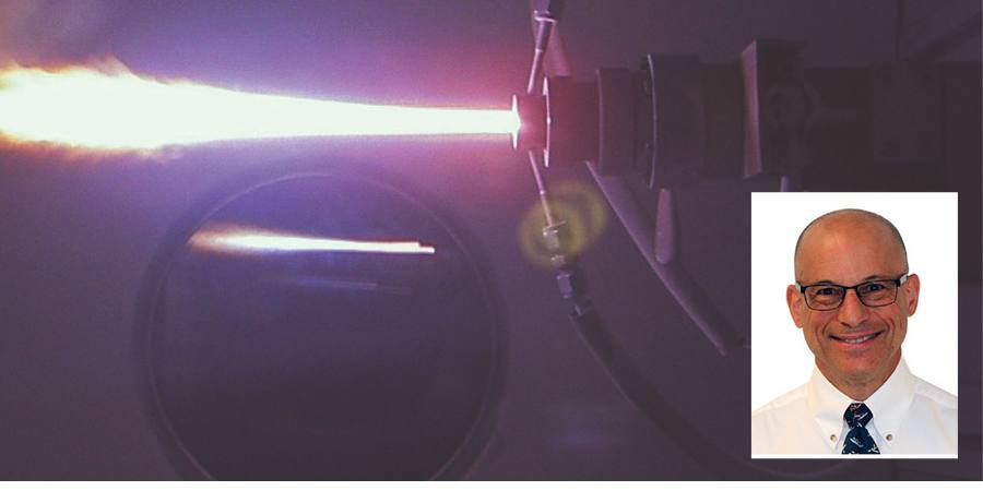
Dan Herring, who is most well known as The Heat Treat Doctor®, has been in the industry for over 50 years. He spent the first 25 years in heat treating prior to launching his consulting business, The HERRING GROUP, in 1995. His vast experience in the field includes materials science, engineering, metallurgy, equipment design, process and application specialist, and new product research. He is the author of six books and over 700 technical articles.

Intern
The Heat Treat Doctor®
Nikolai Alexander Hurley is a young academic, interning with The Heat Treat Doctor®.
For more information: Contact Dan at dherring@heat-treat-doctor.com.

IN 718 Part 2: Heat Treatment Read More »