What is deoxidation and how can it be useful for energy savings? In fact, can the process really save money and improve the quality of iron?
Sometimes our editors find items that are not exactly “heat treat” but do deal with interesting developments in one of our key markets: aerospace, automotive, medical, energy, or general manufacturing. To celebrate getting to the “fringe” of the weekend, Heat Treat Today presents today’s Heat Treat Fringe Friday article that answers these questions. Hint: Deoxidation is helpful, and the article points to how annealing heat treatment may not be necessary in order to meet the ferritic ductile iron elongation specification levels.
An excerpt:
Ductile iron producers typically add copper to the melt to enhance the material’s tensile strength. That becomes unnecessary when base iron is deoxidized prior to magnesium conversion treatment. The deoxidized iron’s strength rises to near 100,000 psi after deoxidation, without copper addition. Deoxidation removes the suspended MgO oxide particles that reduce strength and elongation in ductile iron.
Exothermic gas undergoes a few metamorphoses from the time it is produced to the time it is cooled down after use. Explore the transformations that occur within the combustion chamber to discover the impact these phases can have on the heat treatment atmosphere of your workpieces.
This Technical Tuesday article was composed by Harb Nayar, president and founder, TAT Technologies LLC. It appears in Heat Treat Today'sAugust 2023 Automotive Heat Treating print edition.
Background
Harb Nayar
President and Founder
TAT Technologies LLC
Source: LinkedIn
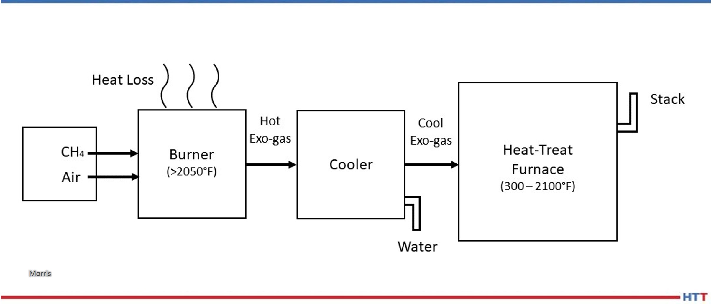
Exothermic gas, more commonly referred to as Exo gas, is produced by partial combustion of hydrocarbon fuels with air in a well-insulated reaction or combustion chamber at temperatures well above 2000°F. Immediately after they exit the combustion chamber, the reaction products are cooled down using water to a temperature below ambient temperature to avoid condensation. The typical dew point of the cooled down Exo gas is about 10°F above the temperature of the water used to cool down. The cooled down Exo is then delivered to the heat treat furnaces where it gets reheated to the operating temperatures between 300°F and 2100°F.
Contact us with your Reader Feedback!
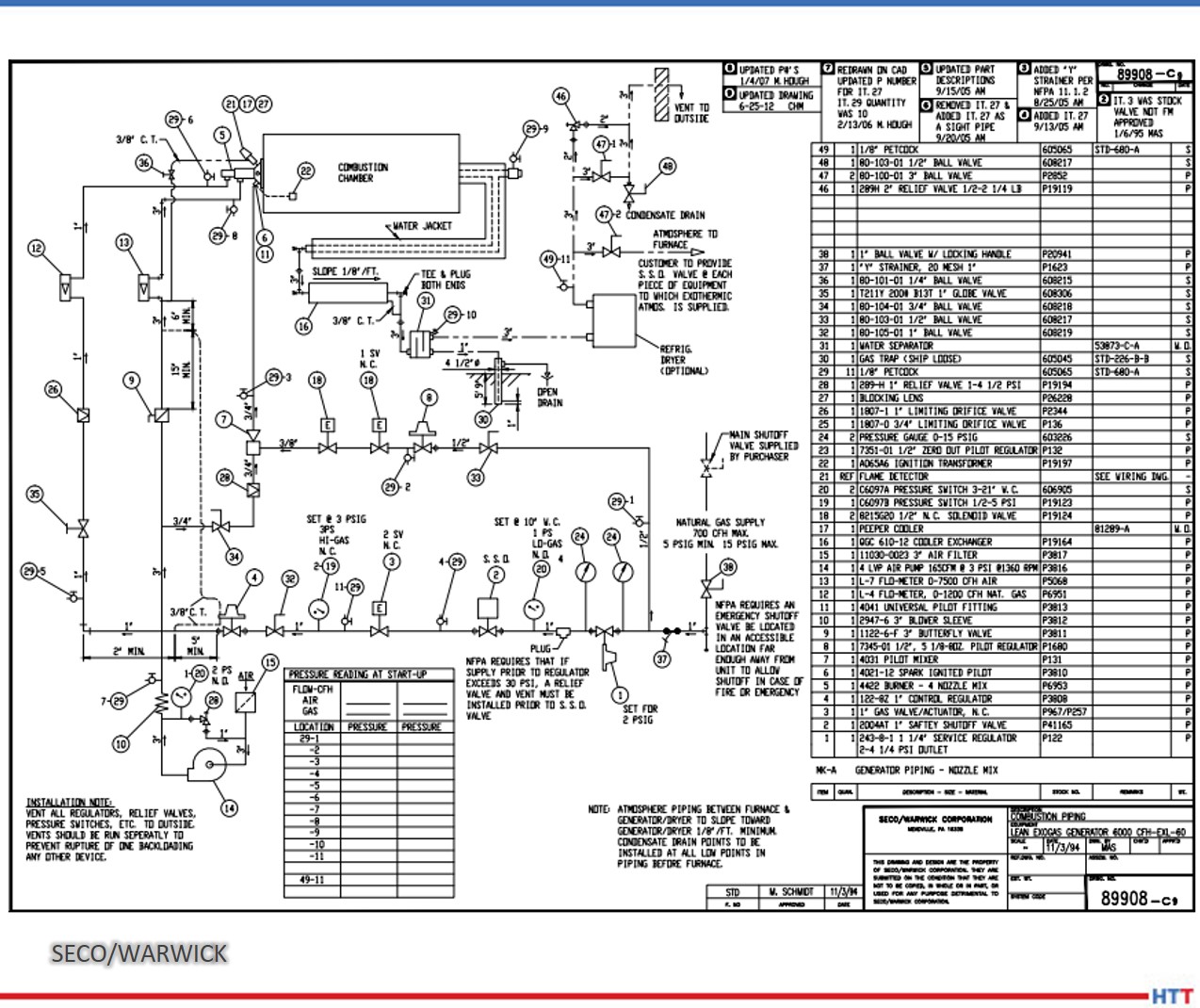
A simplified schematic flow diagram of Exo gas production followed by its cool down below ambient temperature and its final use in heat treat furnaces is shown in Figure 1.
The following aspects of the Exo gas production are clear from Figure 1:
There is lot of energy lost out of the reaction chamber.
There is additional heat lost during cooling using water.
A good deal of water is used for cooling.
The cooled down Exo gas is re-heated to the process temperature in heat treat furnaces.
Exo gas has been predominantly used and is still being used as a source of nitrogen rich atmosphere for purging, blanketing, and mildly oxide reducing applications in the heat treat and metal working industries.
Figure 1. Schematic flow diagram showing Exo production, cool down, and its use.
Source: Morris, “Exothermic Reactions,” 2023
Examples of applications:
Brazing
Annealing
Hardening
Normalizing
Sintering
Tempering, etc.
Examples of materials:
Irons
Steels
Electrical steels
Copper
Copper-base alloys
Aluminum
Jewelry alloys
Examples of product sizes and shapes:
Tubes
Rods
Coils
Sheets
Plates
Components
Small parts, etc.
Exo is the lowest cost gas used in furnaces operating at temperatures above about 700°F to keep air out and provide a protective atmosphere with some oxide reducing potential to the materials being thermally processed.
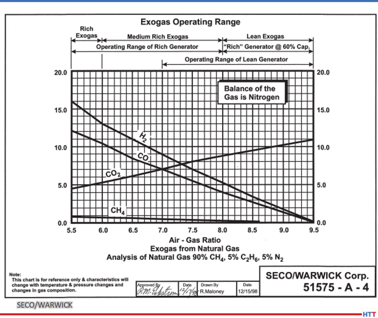
There are two types of Exo gases: lean Exo gas, with mostly nitrogen and carbon dioxide and very little hydrogen, and rich Exo gas, with a little less nitrogen and carbon dioxide and substantially more hydrogen and some carbon monoxide. Typical compositions are given below:
Figure 2. Exo gas operating range
Source: SECO/WARWICK
Figure 2 shows graphs of Exo gas composition at various air to natural gas ratios. H2, CO, and residual CH4 decreases with increasing air to natural gas ratio whereas CO2 goes in the opposite direction. H20 content not shown in the graphs is typically in the 2–4% range depending upon the temperature and cooling efficiency of the cooling system. N2 is the balance which increases with increasing air to natural gas ratio.
The generator designs to produce lean and rich Exo gases are slightly different as shown in the schematic flow diagrams below in Figures 3 and 4.
Objective
This paper will demonstrate a simplified software program (harb-9US) developed recently by TAT Technologies LLC that can easily calculate the reaction products composition, temperature, exothermic energy released, various ratios, and final dew point for various combinations of air and fuel flows entering the reaction chamber at a predetermined temperature and pressure.
The data presented in this paper is under thermodynamically equilibrium conditions only, captured when the reaction is fully completed. It does not tell how long it will take for the reaction to reach completion. However, it can be safely said that reactions are completed relatively fast at temperatures above about 1500°F and very slow at temperatures below about 1000°F. The current software program uses U.S. units: flow in SCFH, pressure in PSIG, temperature in degrees Fahrenheit, and heat as enthalpy in BTU.
The composition of the Exo gas for a fixed incoming air to hydrocarbon fuel ratio changes from production in the combustion chamber to the cool down equipment to bring the Exo gas to below the ambient temperature and finally into the furnace where the material is being heat treated.
Understanding the changes in gas composition from Step 1 (Production in the Combustion Chamber) to Step 2 (Cool Down to Ambient Temperature) to Step 3 (At Temperature of Heat Treated Part) can help to improve the composition, quality, and control of Exo gas that will surround the metallic products being heat treated in the furnace.
Step 1: Composition of Exo Gas as Produced in the Combustion Chamber
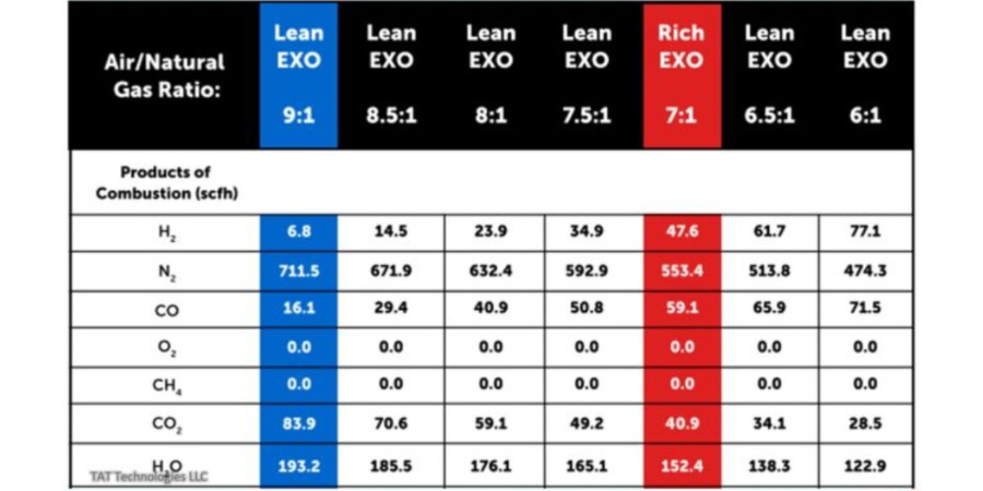
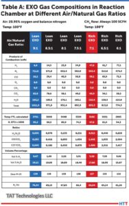
Table A shows the Exo gas compositions as generated within the combustion chamber at various air to natural gas ratios supplied at 100°F and 0.1 PSIG. In these calculations natural gas composition is assumed as 100% CH4 and air is assumed as 20.95% oxygen and balance nitrogen. CH4 is fixed at 100 SCFH and air flow is varied to give air to natural gas ratios between 9 and 6. Typically a ratio of 9 is used for lean Exo and 7 is used for rich Exo applications. Other ratios are used in some special applications.
Table A: Exo gas compositions in reaction chamber based on 100 SCFH of CH4 with air 900, 850, 800, 750, 700, 650, and 600 SCFH to give air to natural gas (CH4) ratios of 9, 8.5, 8, 7.5, 7, 6.5 and 6 respectively. Air and natural gas (CH4) are at 100°F before entering the combustion chamber.
Source: TAT Technologies LLC
The following key conclusions can be made from Table A as one moves from air to natural gas (CH4) ratio of 9 down to 6:
The peak temperature in the reaction chambers goes from a high of 3721°F down to low of 2865°F. Because of high temperatures, good insulation around the combustion chamber is a must. A significant portion of the exothermally generated energy within the reaction chamber is lost to the surroundings.
There is no residual CH4 in the Exo gas composition at these high temperatures. There is no soot (carbon residue) under equilibrium conditions.
H20 content in the natural gas (CH4) gas in the reaction chamber is very high — from high of 19.11% to low of 15.87%. These correspond to dew point 139°F to 132°F — well above the ambient temperature. Because of the very high dew point, the Exo gas coming out of the reaction chamber must be cooled down below the ambient temperature to remove most of the H20 in the Exo gas to avoid any condensation in the pipes carrying the Exo gas toward the furnace and into the
furnace.
H2% changes significantly from 0.67% to 9.96%.
The oxide reducing potential (ORP) as measured by H2/H20 ratio changes from a very low of 0.035 to 0.628. ORP in the reaction chamber is overall quite low because of high percentage of H20.
Nitrogen content varies from 70.34% to 61.26% of the total Exo gas in the reaction chamber.
Exothermic heat generated varies from 95.3 MBTU to 54.34 MBTU — it gradually becomes a less exothermic reaction. Gross heating value of CH4 (at full combustion) is 101.1 MBTU/100 cubic foot of CH4.
Question: What happens to the composition of Exo gas as it cools from peak temperature in the combustion chamber to different lower temperatures after it exits from the combustion chamber?
Answer: It changes a LOT, assuming enough time is provided to reach its equilibrium values during cooling down to any specific temperature. Whenever there is a mixture of gases, such as CH4, H2, H20, CO, CO2,O2, N2, there are a variety of reactions going on between the constituents in the reactant gases to produce different combinations of gas products and heats (absorbed or liberated) at different temperatures. The most popular and well-known reactions are:
Partial Oxidation Reaction: CH4+ 1/2O2 → CO + 2H2 — exothermic. The reaction becomes more exothermic as O2 increases from 0.5 to 2.
Water Gas Shift Reaction: CO + H20 → CO2 + H2 — slightly exothermic. It usually takes place at higher temperatures faster. A catalyst in the reaction chamber can help to lower the high temperature requirement. There are many catalysts. Commonly used are either Ni or precious metals.
CO2 Reforming Reaction: CH4 + CO2 → 2CO + 2H2 — endothermic.
All of these reactions have different degrees of influences from changes in temperature. One could say that the final equilibrium composition of the Exo gas is a continuously moving target as temperature changes. Only the N2 portion stays constant. One can make the following generalized statements covering a broad range of Exo gases (lean and rich) in the reaction chamber:
a) N2 content does not change. It remains neutral at all temperatures.
b) H2 content decreases with increasing temperature.
c) H20 (vapor) content increases with increasing temperature.
d) CO content increases with increasing temperature.
e) CO2 content decreases with increasing temperature.
f) Residual CH4 decreases with increasing temperature.
g) Soot decreases with increasing temperature.
h) Catalysts facilitate the speed of reactions at any temperature.
Conclusion
Exo gas composition changes during its time in the combustion chamber. Reaction products composition, temperature, exothermic energy released, various ratios, and final dew point are all items that need to be taken into consideration to protect the metallic pieces that will be heat treated in the resulting atmosphere. Part 2 will demonstrate this principle and discuss Step 2 (Cool Down to Ambient Temperature) and Step 3 (At Temperature of Heat Treated Part).
About the author:
Harb Nayar is the founder and president of TAT Technologies LLC. Harb is both an inquisitive learner and dynamic entrepreneur who will share his current interests in the powder metal industry, and what he anticipates for the future of the industry, especially where it bisects with heat treating
What process holds a soft spot in your heart? Tempering or annealing? For Valentine's Day, turn up the heat -- errr heat treatments -- with this look at the differences in tempering and annealing! Heat TreatToday has resources for you to spark some thought and learning on these processes.
Sentiments and strong feelings can certainly be heightened this Valentine's Day. While tempering and annealing may not lend themselves easily to the holiday, we hope you enjoy a bit of a nod to the day in our headings below. Make use of the Reader Feedback button, too, and keep us in the loop with questions and comments on what heat treatment you love.
Problem with Annealing? Get to the Heart of the Issue
An automotive parts manufacturer was running into problems with cracking parts. The variable valve timing plates were returning from heat treatment with this problem. To determine why those parts were cracking after the annealing process, an investigation was launched by metallurgists at Paulo.
The presence of nitrogen combining with the aluminum already present in the particular steel being used was forming aluminum nitrides. What could be done? Read more in the case study article below to find out a workable solution that allowed the annealing to create a crack-free product.
Induction, Rapid Air, Oven and Furnace Tempering: Which One do You Love?
Contact us with your Reader Feedback!
This article gives some perspectives, from experts in the field, on what kinds of tempering are available and for what the processes are used.
Hear from Bill Stuehr of Induction Tooling, Mike Zaharof of Inductoheat, and Mike Grande of Wisconsin Oven with some basics and background information on tempering. Those reasons alone make this resource helpful with information like this: "tempering at higher temperatures results in lower hardness and increased ductility," says Mike Grande, vice president of sales at Wisconsin Oven. "Tempering at lower temperatures provides a harder steel that is less ductile."
More specific in-depth study is presented as well. The Larson-Miller equation is considered, and the importance of temperature uniformity is emphasized. Read more of the perspectives: "Tempering: 4 Perspectives — Which makes sense for you?"
Cast or Wrought Radiant Tubes in Annealing Furnaces - is Cheaper Really What to Fall For?
Marc Glasser, director of Metallurgical Services at Rolled Alloys, takes a look at radiant tubes. He particularly discusses the cast tubes and wrought tubes. For use in continuous annealing furnaces, there are several factors contributing to choice of radiant tube type.
Marc says, "Justification for the higher cost wrought alloy needs to take into consideration initial fabricated tube cost, actual tube life, AND the lost production of each anticipated downtime cycle as these downtime costs are often much more than material costs." He probes into areas that may not be considered when thinking of all the costs involved. Read more of his article "Radiant Tubes: Exploring Your Options."
Tempering Furnaces: Improvements are Thrilling
The expert behind this piece shows the importance of tempering, particularly in automotive fastener production. Tim Donofrio, vice president of sales at CAN-ENG Furnaces International Limited examines what's working in the tempering furnaces. The products are meeting and exceeding expectations.
To wrap up this Technical Tuesday post on tempering and annealing, head over to this additional resource to round out the scope of each process. "What is the Difference: Tempering VS. Annealing" gives a summary perspective on the heat treatments discussed above.
Find heat treating products and services when you search on Heat Treat Buyers Guide.com
There are many radiant tube options on the market, so which one is best for your furnace and your budget? In this column that compares radiant tubes in carburizing and continuous annealing furnaces, discover how two major types of radiant tubes stack up.
Marc Glasser, director of Metallurgical Services at Rolled Alloys, investigates more deeply the two choices. This Technical Tuesday discussion on radiant tubes options will be published inHeat Treat Today'sFebruary 2023 Air & Atmosphere Heat Treating Systems digital edition.
Introduction
Marc Glasser Director of Metallurgical Services Rolled Alloys Source: Rolled Alloys
Radiant tubes are used in many types of heat treating furnaces from carburizing furnaces to continuous annealing of steel strip. Generally, a heat treater has three options for radiant tubes: cast tubes, wrought tubes, and ceramic silicon carbide tubes. Silicon carbide tubes are rarely used by heat treaters, so this article will not delve too deeply into this option. Suffice it to say, ceramic materials can often handle much higher temperatures at the expense of ductility; ceramics are more brittle than metals, making them prone to failure from the small impacts, so metal cages are sometimes fabricated to protect them. Most of the tubes being used today are cast radiant tubes. With new casting technology — primarily centrifugal casting — thinner tubes are being cast at a lower cost, which then results in a shorter life.
The primary factors for choosing radiant tube material are tube temperature and carbon potential of the furnace atmosphere. Cost-benefit analysis should also be considered. There are multiple applications for radiant tubes, including carburizing furnaces, continuous annealing furnaces for steel sheet galvanizing, steel reheat furnaces, and aluminum heat treating. This article will explore two of the aforementioned radiant tube options, specifically for carburizing and continuous annealing furnaces.
Radiant Tubes for Carburizing Furnaces
Gas carburization is traditionally performed between 1650°F and 1700°F at a carbon potential of 0.8% approximating the eutectoid composition. In today’s competitive environment, more heat treaters are increasing temperatures to 1750°F and pushing carbon potentials as high as 1.6% to get faster diffusion of carbon while spending less time at temperature. INCONEL® HX (66% Ni, 17% Cr) has been a common cast alloy seen in carburizing furnaces. This alloy is regularly selected for its resistance to oxidation and carburization up to 2100°F. Super 22H is more heavily alloyed than HX and is seeing more use as carbon potentials increase but at a premium price. With advances in centrifugal castings, cast tube wall thicknesses have decreased from 3/8-inch to 1/4-inch. Some heat treaters have shared that this decrease in wall thickness has also led to shorter tube life.
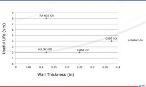
Fabricated and welded radiant tubes in alloys 601 and RA 602 CA® have been tested in industry. When tested, these wrought alloys were fabricated to have a wall thickness of 1/8-inch. At the extremes, tubes fabricated from 601 only lasted 50% as long as cast HX. Historically, HX tubes have been approximately 33% higher in cost than that of 601 and utilize heavier 3/8-inch walls. A little-known fact is that by switching to a thinner wall cast tube, the life drops by 50%. By switching to 1/8-inch wall thickness, RA 602 CA tube life has been extended to eight years or more, while running at 1750°F and up to 1.6% carbon potential, at just a 33% premium over cast HX. Life cycle data are presented in Figure 1.
Figure 1. These life cycle comparisons were done in carburizing furnaces only. In non-carburizing furnaces, justification of alloy selection is dependent on actual operating conditions and each individual operator’s own experience. Source: Rolled Alloys
Radiant Tubes for Continuous Annealing Furnaces
In the area of continuous annealing, the cast alloy of choice is HP/HT (35% Ni, 17% Cr, 1.7% Si, 0.5% C). Here again, this casting has been compared to 601 and RA 602 CA, with the same results. The total life data from these trials are also incorporated into Figure 1. During the collection of this data, there has been no effort to measure the actual tube temperature, so the effect of tube temperature is not clearly defined. In these continuous annealing furnaces, it has been reported that the tubes at the entry end are subject to more heat absorption as burners are firing more due to the continuous introduction of cold material; in trials, the operators have not kept adequate documentation of specific tubes, making justification more diffcult.
Justification for the higher cost wrought alloy needs to take into consideration initial fabricated tube cost, actual tube life, AND the lost production of each anticipated downtime cycle as these downtime costs are often much more than material costs. Only individual fabricators can determine these costs.
The Economics
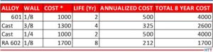
Table 1 Source: Rolled Alloys
Table 1 above shows the economics of metal alloy choice. To properly interpret, understand that the costs are not actual, but rather relative to 601, so a round number of 1000 was used. With a 30% greater cost of cast tubes, that translates to a relative cost of $1300. The annual cost is the amortized cost over the life of the tube. The total eight-year cost is the relative cost times the number of tubes that would have to be purchased to obtain the life cycle of one tube of the longest-lasting material over its full life cycle.
Missing in this analysis is the additional cost of downtime and lost production. For the replacement of radiant tubes in a carburizing furnace, this typically entails a full week to turn a furnace off, allow it to cool, replace the tubes, and then heat it up again. Many heat treaters do not consider this, and therefore it is a hidden cost. Even without the downtime being considered, by examining the total cost of materials (including replacements) compared to the longest-lasting tube, it turns out that the most expensive tube is the cheapest tube. The obstacle to overcome is whether the heat treater is willing to wait eight years to realize these cost savings.
There can be additional factors to consider. With improvements in the efficiency of casting, the actual costs of the thinner wall casting may be somewhat less, but to match the overall cost of the longest-life material, it would have to be less than half the expected cost. As better, more expensive cast alloys become accepted and actual life data becomes available, these more costly alloys can be added to this table for comparative analysis, too.
This same method of analysis can be applied to radiant tubes for continuous annealing furnaces, but more details will need to be added including furnace position. Different alloy candidates will have to be put to the test in actual operations, carefully document what alloy is in what position or location, and when it gets changed out. This becomes quite cumbersome when annealing furnaces (depending on design and manufacture) can have over 200 radiant tubes.
Conclusion
Currently, cast alloy tubes dominate the market. The concept of total life cycle cost has been introduced as a means of more accurately justifying one’s choice of radiant tube. This comes into play more as processes are pushed beyond traditional process conditions. Cost-benefit analysis must be balanced over acceptable amortization time, of course. However, performing the full analysis as well as the costs saved from downtime may lead some heat treaters to some alternate materials.
About the author: Marc Glasser is the director of Metallurgical Services at Rolled Alloys and is an expert in process metallurgy, heat treatment, materials of construction, and materials science and testing. Marc received his bachelor’s degree in materials engineering from Rensselaer Polytechnic Institute and a master’s degree in material science from Polytechnic University, now known as the NYU School of Engineering. Contact Marc at mglasser@rolledalloys.com
Find heat treating products and services when you search on Heat Treat Buyers Guide.com
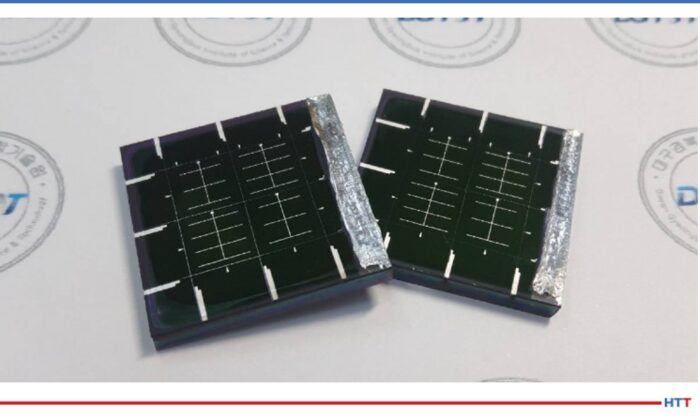
Solar Panels (photo source: InterestingEngineering.com)
Sometimes our editors find items that are not exactly "heat treat" but do deal with interesting developments in one of our key markets: aerospace, automotive, medical, energy, or general manufacturing. To celebrate getting to the "fringe" of the weekend, Heat Treat Today presents today's Heat Treat Fringe Friday Best of the Web article on efficient alloy-based solar panels. These solar panels are free of toxic metals and can be implemented in producing electronic devices, buildings, and vehicles.
Check out how scientists from Daegu Gyeongbuk Institute of Science and Technology in South Korea were able to overcome issues of underperformance in this article by Interesting Engineering: "Efficient Alloy-Based Solar Panels Created Free of Toxic Metals."
An excerpt: "'Thin-film solar cells using bronze (Cu-Sn) and brass (Cu-Zn) as base materials are composed of non-toxic earth-abundant materials, and have been studied worldwide because of their low cost, high durability, and sustainability,' said Kang[...] While theoretically they are said to perform as well as top market products, in reality, they severely underperform[...] The scientists looked for a way to bypass these flaws and produce the best quality CZTSSe (copper, zinc, tin, sulfur, and selenium) thin films. They came up with the ingenious solution..."
A Chicago-area automotive part supplier encountered frequent cracking of variable valve timing plates that were sent to a third party for heat treatment. The problem resulted in the company spending lots of time and money on part testing as well as wasting lots of steel. After a thorough examination of the manufacture and heat treatment of the parts, Paulo metallurgists identified the cause of the cracking and recommended a custom solution to keep it from happening in the future. The following is a case study on the part failure investigation and resolution by Rob Simons.
Case study of a part failure investigation and resolution
Being an integral part of customers’ success means more than just regularly receiving parts and treating them according to spec.
Sometimes a customer approaches a heat treater in search of answers to a problem they can’t quite grasp.
In this case, a Chicago-area supplier of automotive components needed to know why parts it sent off for heat treating kept coming back cracked. They were spending too much time and resources on tests and throwing out too many failed parts.
Persistent cracks in variable timing plates
Our customer produces variable valve timing plates for domestic automobile models. Variable valve timing (VVT) plates are part of a system designed to optimize engine performance by changing the lift, duration, and timing of valve lift events.
Variable Valve Timing Plates (Photo credit: Underhood Service http://www.underhoodservice.com/variable-valve-timing/)
In this case, the life cycle of these parts began in a steel mill, where coils of AISI 1045 carbon steel were produced. The parts were then annealed in preparation for fine blanking at our customer’s facility. Then, the parts would be through hardened and sent to the automotive manufacturer.
But our customer noticed that many of the parts came back cracked. This was the source of two big problems:
The customer had to perform inspections on every part that was returned from the heat treater, which came at significant expense of time and resources.
To satisfy the terms of its contract with the automotive manufacturer, our customer had to make far more parts than it would have ordinarily needed to on the assumption that many of the parts would not be acceptable. It cost too much money, and too much steel was wasted.
The customer approached metallurgists at Paulo to figure out what was wrong and what could be done to make it right.
Forensic heat treatment analysis
Our first task was to figure out what the customer’s heat treater was doing to the parts.
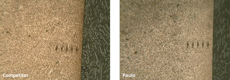
Upon our inspection, we noticed the parts were quite brittle. A closer look at the microstructure of the parts’ surfaces revealed they had been carbonitrided.
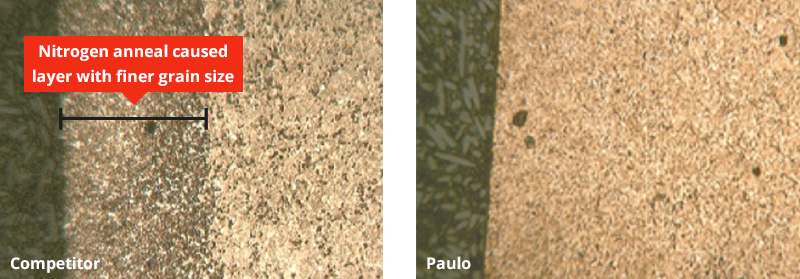
Meanwhile, we consulted with personnel at the mill and steel processor where the steel originated. We learned that the coils of 1045 steel were annealed in a nitrogen environment. Annealing is an important process that spheroidizes carbides in the steel which aids in fine blanking. In the case of our customer, the VVT plates could not be formed to the specified tolerance if they weren’t first annealed.
But the nitrogen present in the anneal was a problem. 1045 steel includes aluminum as a grain refining element. When aluminum and nitrogen combine during annealing, aluminum nitrides form. Aluminum nitrides create a much finer grain on the part surface, which prevents the full hardening of the material. We suspected our customer’s heat treater attempted to overcome the defect by carbonitriding. But instead of hardening, the parts just got brittle. That’s because 1045 steel lacks the hardenability that would be required to overcome the fine grain size that resulted from the presence of aluminum nitrides.
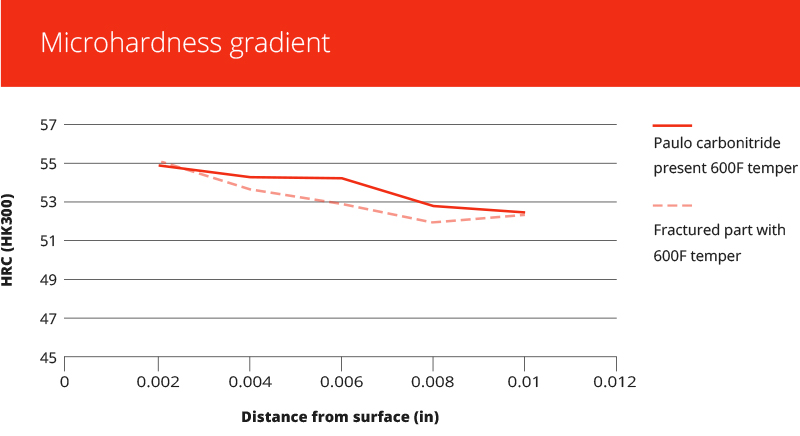
To confirm our suspicion, we ordered the same material from the customer’s mill and then carbonitrided the parts as we believed the previous heat treater had. Our post-treatment analysis of the parts shows the successful recreation of the failure mode.
A custom-developed solution
We believed the most direct way to solve the problem was to eliminate the factors that caused it at the start. We again approached the mill, this time to see if they could anneal the steel in a different environment. They said they could not.
The next best thing would be to “spike” the 1045 steel with another alloying element that would add hardenability despite the fine grain sizes that result when nitrogen and aluminum interact during annealing. We pinpointed chromium as the ideal alloy, and after some trial and error, we identified a formula for the chromium spike that would result in fully-hardened parts without cracks after through hardening.
Today, the customer’s mill still produces the 1045 steel with our recommended chromium spike. And as of mid-2018, we’ve treated 25 million variable valve timing plates for this customer.
This case study illustrates the importance of a few key lessons suppliers should keep in mind. First, stay in touch with what’s going on further up the supply chain. You may be able to react to problems more quickly or stop them altogether.
Second, have a working knowledge of part materials and the chemistry at play during any manufacturing process. Armed with this knowledge, you can ask key questions as you vet potential heat treatment partners. It could end up saving you time and expense in the long run.
Finally, know where to get a second opinion, and have a backup heat treater ready in case your primary partner can’t do what you need them to do.
Rob Simons is a metallurgical engineer specializing in ferrous heat treatments with 35 years of experience in the industry. He earned a degree in metallurgical engineering from the University of Missouri – Rolla in 1982 and most recently was a featured presenter at the ASM Heat Treat 2017 conference. He has been at Paulo for over 30 years.
When steel needs to be softened to alter ductility, toughness, or properties, or to produce a specific microstructure, a heat treater can turn to any one or combination of processes to suit the material or the application.
Metlab Heat Treat’s primer series includes a short explanation of the options available, whether it is
annealing, which “removes the internal stresses, which build up as a result of cold working and other fabrication processes;”
protective atmosphere normalizing, which “refines the grain size and enhances the uniformity of the microstructure;” or
spheroidize annealing, which “is generally done on parts which have been work hardened, to allow them to be further worked, either rolled in the case of coils, or drawn for wire.”
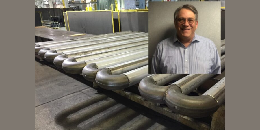
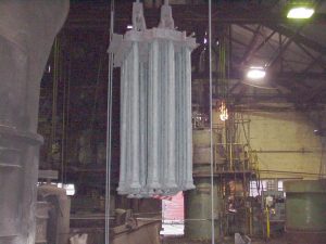
1.) Load of torsion bars, manufactured from 4340 steel, normalized in the vertical position to maintain straightness. Parts measure approximately 3\” in diameter by 6\’ long.
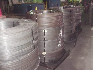
2.) 26,000 pounds of low carbon steel flat wire being prepared for spheroidize annealing. Spheroidize annealing is an intermediate processing step to allow the wire to be further rolled to a smaller gage without cracking.
Heat treating more often than not includes the process of annealing in order to induce precise softness; to alter ductility, strength, or properties; or to produce a definite microstructure. Because of the wide variety of steels and metal alloys, it is important for heat treaters to match the correct annealing process with the steel grade and to the application of the parts being treated.
Machine Manufacturing has provided a summary of the annealing process and listed seven types of annealing, describing the process and the objectives for each. Included in the list are:
And to take the analysis into more specific types of annealing, over at Knergize.com, Dr. S.B. Sarkar discusses Spheroidized Annealing and its benefit to bearing manufacturers, describing the metallurgical science behind the process, noting the need to adhere to international standards and specifications, and addressing equipment management and quality control of the process.
Researchers at Toyohashi University of Technology have collaborated with their counterparts at Massachusetts Institute of Technology (MIT) to develop a new material capable of retaining high transmissivity after annealing at 850°C (1562°F). The results address the challenge manufacturers face when combining different materials that react differently to heat treatment at certain temperatures.
BILSTEIN CEE a.s, based in the Czech Republic, is part of the globally active BILSTEIN GROUP. The BILSTEIN GROUP produces various grades of high-quality cold rolled strip for a wide variety of applications.
Two years ago an order was placed with EBNER to supply a HICON/H2® bell annealer facility to heat treat steel strip coils, comprising four workbases.
Although this facility was commissioned successfully less than one year ago, BILSTEIN CEE a.s. awarded EBNER the contract for the expansion of this facility by a further three workbases.
The new workbases will be commissioned in 2017, increasing production by about 60%.