Heat Treat Today publishes eight print magazines a year, and included in each is a letter from the publisher, Doug Glenn. This letter first appeared in December 2023 Medical and Energy Heat Treatprint edition.
. . . not as bad as predicted. In fact, it was a pretty darn good year for the North American heat treat industry.
Russia and Ukraine
Doug Glenn, Publisher, Heat Treat Today
This time last year, there were many predictions about a pending economic slump in varying degrees of severity. Russia’s invasion of Ukraine on February 22, 2022, was front-page news most of 2022. When Russia cut off the flow of natural gas from Russia to Europe through the Nord Stream 1 pipeline in September 2022, Europe, and much of the world, planned on a very cold winter and cooling economies around the world in 2023. While Europe certainly took a hit with energy prices that were sometimes 3x what they had been, most of the rest of the world adjusted quite nicely. Even the United States did well in 2023 despite our federal government’s insistence on reducing and eliminating petroleum-based flows of energy which are in abundant supply.
Titanium supplies were also predicted to take a huge hit with Russia being one of the chief suppliers. But since a May 2022 high of roughly $19/ kg, the price of titanium has been dropping steadily back into a pre-conflict price of roughly $6/kg. Only $2/kg higher than the average price of titanium from 2017 to 2022. Not bad.
Of course, the macro effects of the billions of dollars that the U.S. has sent to Ukraine remain to be seen; in economic terms, 2023 turned out to be not as bad as predicted when it comes to the Russia-Ukraine conflict, at least for the U.S.
2023 Recession . . . that Wasn’t
“And for 2024, let’s be optimistic and prayerful that God will again be merciful and not reward us as we deserve!”
Thanks to the U.S. federal government’s now widely agreed upon over-reaction to COVID in the form of “quantitative easing” (meaning pumping the economy full of money created out of thin air), nearly everyone in 2022 was predicting a significant economic recession in 2023. It was just a matter of when, not if. At the time of writing this (early November), it doesn’t appear likely that the U.S. will see a recession in the remaining months of the year. In fact, most of the company leaders that I’ve spoken to this year have reported (surprisingly) strong orders, growing backlogs, and very little signs of slowing inquiry levels. Nearly everyone is busy with no end in sight. Even in the face of rising interest rates — the highest in nearly 30 years — capital equipment purchases seem to be clipping along very nicely. Everyone is surprised, but happy.
Israel, AI, and Other Disruptors
That’s not to say the world and the North American heat treat market’s place in the world is all roses. It is not. 2024 will have its own list of significant challenges, not the least of which is growing global instability à la China, Iran, Russia, Israel, etc. and the U.S.’s participation therewith. The advent of digital currencies could be another disruptor. Artificial Intelligence (AI) seems to be approaching at warp speed — no one is quite sure what it is, but we’re all pretty sure it will have an impact.
Regardless of what God has in store for us in 2024, 2023 has certainly not been as bad as it was predicted to be in December 2022. For that we can be thankful. And for 2024, let’s be optimistic and prayerful that God will again be merciful and not reward us as we deserve!
All of us at Heat Treat Today wish you, your family, and your business a Merry Christmas and a blessed and prosperous 2024.
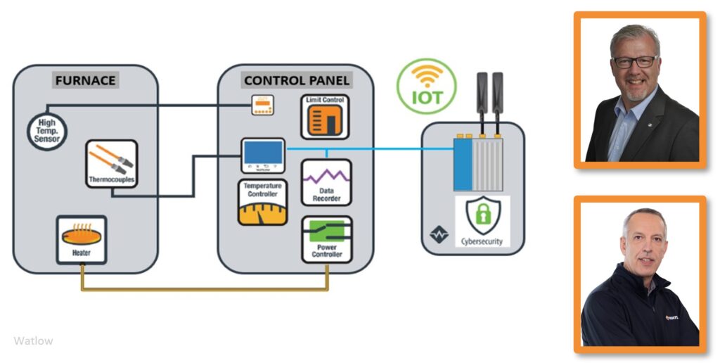
How often do you think about the intelligent designs controlling the thermal loop system behind your heat treat operations? With ever-advancing abilities to integrate and manage data for temperature measurement and power usage, the ability of heat treat operations to make practical, efficient, and energy-conscious change is stronger than ever. In part 1, understand several benefits of thermal loop systems and how they are leveraged to comply with industry regulations, like Nadcap.
This Technical Tuesday article by Peter Sherwin, global business development manager – Heat Treatment, and Thomas Ruecker, senior business development manager, at Watlowwas originally published inHeat Treat Today’sJanuary/February 2024 Air & Atmosphere Heat Treat print edition.
Introduction
Heat treatment processes are a crucial component of many manufacturing industries, and thermal loop solutions have become increasingly popular for achieving improved temperature control and consistent outcomes.
A thermal loop solution is a closed loop system with several essential components, including an electrical power supply, power controller, heating element, temperature sensor, and process controller. The electrical power supply provides the energy needed for heating, the power controller regulates the power output to the heating element, the heating element heats the material, and the temperature sensor measures the temperature. Finally, the process controller adjusts the power output to maintain the desired temperature for the specified duration, providing better temperature control and consistent outcomes.
Performance Benefits
Heat treatment thermal loop solutions offer several advantages over traditional heat treatment methods, including improved temperature control and increased efficiency. The thermal loop system provides precise temperature control, enabling faster heating and cooling and optimized soak times. In addition, the complete design of modern thermal loop solutions includes energy-efficient heating and overall ease of use.
Figure 1. Watlow Industry 4.0 solution (Source: Watlow)
Heat treatment thermal loop solutions are integrated with Industry 4.0 frameworks and data management systems to provide real-time information on performance. Combining artificial intelligence and machine learning algorithms can also provide additional performance benefits, such as the ability to analyze data and identify patterns for further optimization. Ongoing performance losses in a heat treatment system typically come from process drift s. Industry 4.0 solutions can explore these drift s and provide opportunities to minimize these deviations.
Heat treatment thermal loop solutions can be optimized using Failure Mode and Effects Analysis (FMEA). FMEA is a proactive approach to identifying potential failure modes and their effects, allowing organizations to minimize the risk of process disruptions and improve the overall efficiency of their heat treatment processes. Historically, this was a tabletop exercise conducted once per year with a diverse team from across the organization. Updates to this static document were infrequent and were primarily based on organization memory rather than being automatically populated in real time with actual data. There is a potential to produce “live” FMEAs utilizing today’s technology and leveraging insights for continuous improvement.
Th e effectiveness of heat treatment thermal loop solutions can be measured using metrics such as overall equipment effectiveness (OEE). OEE combines metrics for availability, performance, and quality to provide a comprehensive view of the efficiency of a manufacturing process. By tracking OEE and contextual data, organizations can evaluate the effectiveness of their heat treatment thermal loop solutions and make informed decisions about optimizing their operations.
Regulatory Compliance
Nadcap (National Aerospace and Defense Contractors Accreditation Program) is an industry-driven program that provides accreditation for special processes in the aerospace and defense industries. Heat treatment is considered a “special process” under Nadcap because it has specific characteristics crucial to aerospace and defense components’ quality, safety, and performance. Th ese characteristics include:
Process sensitivity: Heat treatment processes involve precise control of temperature, time, and atmosphere to achieve the desired material properties. Minor variations in these parameters can significantly change the mechanical and metallurgical properties of the treated components. This sensitivity makes heat treatment a critical process in the aerospace and defense industries.
Limited traceability: Heat treatment processes typically result in changes to the material’s microstructure, which are not easily detectable through visual inspection or non-destructive testing methods. Th is limited traceability makes it crucial to have strict process controls to ensure the desired outcome is achieved consistently.
Critical performance requirements: Aerospace and defense components often have strict performance requirements due to the extreme conditions in which they operate, such as high temperatures, high loads, or corrosive environments. The heat treatment process ensures that these components meet the specifications and can withstand these demanding conditions.
High risk: The failure of a critical component in the aerospace or defense sector can result in catastrophic consequences, including loss of life, significant financial loss, and reputational damage. Ensuring that heat treatment processes meet stringent quality and safety standards is essential to mitigate these risks.
Nadcap heat treatment accreditation ensures suppliers meet industry standards January/February and best practices for heat treatment processes. The accreditation process includes rigorous audits, thorough documentation, and ongoing process control monitoring to maintain high quality, safety, and performance levels.
The aerospace industry’s AMS2750G pyrometry specification and the automotive industry’s CQI-9 4th Edition regulations are crucial for ensuring consistent and high-quality heat treated components. Adherence to these regulations is essential for meeting the stringent quality requirements of the aerospace and automotive industries and other industries with demanding specifications.
Temperature uniformity is a crucial requirement of both AMS2750G and CQI-9 4th Edition, mandating specific temperature uniformity requirements for heat treating furnaces to ensure the desired mechanical properties are achieved throughout the treated components. AMS2750G class 1 furnaces with strict uniformity requirements +/-5°F (+/-3°C) provide both quality output and predictable energy use. However, maintaining this uniformity requires significant maintenance oversight due to all the components involved in the thermal loop.
Calibration and testing procedures are specified in the standards to help ensure the accuracy and reliability of the temperature control systems used in heat treat processes.
Detailed process documentation is required by AMS2750G and CQI-9 4th Edition, including temperature uniformity surveys, calibration records, and furnace classifications. This documentation ensures traceability, enabling manufacturers to verify that the heat treat process is consistently controlled and meets the required specifications.
Figure 2. Eurotherm data reviewer (Source: Watlow)
Modern data platforms enable the efficient collection of secure raw data (tamper-evident) and provide the replay and reporting necessary to meet the standards.
The newer platforms also offer the latest industry communication protocols – like MQTT and OPC UA (Open Platform Communications Unified Architecture) – to ease data transfer across enterprise systems.
MQTT is a lightweight, publish-subscribe-based messaging protocol for resource-constrained devices and low-bandwidth, high-latency, or unreliable networks. IBM developed it in the late 1990s, and it has become a popular choice for IoT applications due to its simplicity and efficiency. MQTT uses a central broker to manage the communication between devices, which publish data to “topics,” and subscribe to topics that they want to receive updates on.
OPC UA is a platform-independent, service-oriented architecture (SOA) developed by the OPC Foundation. It provides a unified framework for industrial automation and facilitates secure, reliable, and efficient communication between devices, controllers, and software applications. OPC UA is designed to be interoperable across multiple platforms and operating systems, allowing for seamless integration of devices and systems from different vendors. The importance of personnel and training is emphasized by CQI-9 4th Edition, which requires manufacturers to establish training programs and maintain records of personnel qualifications to ensure that individuals responsible for heat treat processes are knowledgeable and competent. With touchscreen and mobile integration, a significant development in process controls has occurred over the last decade.
Figure 3. Watlow F4T® touchscreen and Watlow PM PLUS™ EZ-LINK®
mobile application
By integrating these regulations into a precision control loop, heat treatment thermal loop solutions can provide the necessary level of control and ensure compliance with AMS2750G and CQI-9 4th Edition, leading to the production of high-quality heat treated components that meet performance requirements and safety standards.
Continuous improvement is also emphasized by both AMS2750G and CQI-9 4th Edition, requiring manufacturers to establish a system for monitoring, measuring, and analyzing the performance of their heat treatment systems. This development enables manufacturers to identify areas for improvement and implement corrective actions, ensuring that heat treat processes are continuously improving and meeting the necessary performance and safety standards.
To Be Continued in Part 2
In part 2 of this article, we’ll consider the improved sustainability outcomes, potential challenges and limitations, and the promising future this technology offers to the heat treat industry.
About the Authors
Peter Sherwin, Global Business Development Manager – Heat Treatment, WatlowThomas Ruecker, Senior Business Development Manager, Watlow
Peter Sherwin is a global business development manager of Heat Treatment for Watlow and is passionate about offering best-in-class solutions to the heat treatment industry. He is a chartered engineer and a recognized expert in heat treatment control and data solutions.
Thomas Ruecker is the business development manager of Heat Treatment at Eurotherm Germany, a Watlow company. His expertise includes concept development for the automation of heat treatment plants, with a focus on aerospace and automotive industry according to existing regulations (AMS2750, CQI-9).
For more information: Contact peter.sherwin@watlow.com or thomas.ruecker@watlow.com.
This article content is used with the permission of heat processing, which published this article in 2023.
Find Heat Treating Products And Services When You Search On Heat Treat Buyers Guide.Com
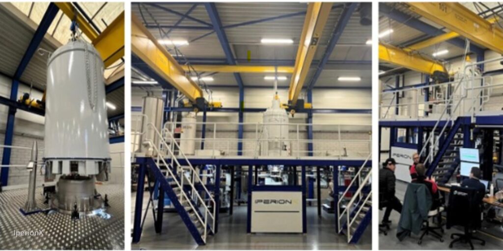
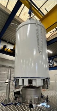
HAMR titanium furnace for Virginia facility (Source: IperionX)
IperionX announced their HAMR (Hydrogen Assisted Metallothermic Reduction) furnace has completed its final mechanical assembly and passed factory acceptance tests. The furnace will be delivered to the company’s Virginia Titanium Production Facility as a foundational asset to the low-cost titanium supply chain.
The HAMR furnace is a large-scale titanium furnace with IperionX-patented technologies. HAMR is a powder metallurgy process technology that allows for the production of titanium powders.
Installation is expected during 2024’s second quarter, with production of titanium beginning mid-2024. To ramp up low-cost titanium production, IperionX has received $2.4 million from the DoD as part of a $12.7 million grant fund.
To learn more about IperionX’s Viriginia Titanium Production Facility, visit this link.
This press release is available in its original form here.
Mike Moyer Vice President of Sales, Solar Atmospheres, Eastern PA
Solar Atmospheres of Souderton PA commissioned a new vacuum furnace capable of utilizing high pressure gas quenching (HPGQ) at 20-Bar (about 300 PSI) to meet demanding cooling rate specifications for the heat treatment of nickel-based superalloys in the aerospace and power generation industries.
The vacuum furnace, manufactured by sister company Solar Manufacturing, has a working hot zone of 24” x 24” x 72” and utilizes unique hot zone design features to increase the quench rate. The furnace is rated for operation to 2400°F and temperature uniformity plus/minus 10°F.
Mike Moyer, vice president of Sales at Solar Atmospheres comments, “The furnace utilizes a 600-HP cooling motor and fan with a creative gas nozzle design to maximize gas flow as it moves through the hot zone and the heat exchanger and back across the workload.”
The full press release from Solar Atmospheres is available upon request.
How long until heat treat operations use hydrogen for combustion? Considerations like cost and pipeline infrastructure are key in answering this question. For these industry experts, the consensus is clear: It is uncertain when, but hydrogen is coming. Doug Glenn, publisher of Heat Treat Today, moderated a panel of four industry experts in 2023 during which they addressed topics about advancements and challenges surrounding hydrogen combustion. Read an excerpt of their answers below. For the full interview go to www.heattreattoday.com/hydrogen2023.
What’s New for Hydrogen?
Dr.-Ing. Joachim G. Wuenning President/Owner WS Wärmeprozesstechnik GmbH
Joe Wuenning: In Europe, several steel companies are getting large funds to really go in on the hydrogen road to make green steel. If you have green steel, you will also convert the downstream processes. These places are large locations where the steel plants are running.
Automotive companies will ask for green steel. How long will it take until the heat treat shop will get to the point of using hydrogen for combustion is uncertain, but I’m sure it will be, in the end, coming also there.
Brian Kelly Applications Engineering Manager Honeywell Thermal Solutions
Brian Kelly: We have seen projects secured that have come to fruition firing on hydrogen. They’ve fired on hydrogen to prove it works and then moved back to natural gas since the H2 supply is not readily available.
What we’ve seen in the U.S. is a slowdown in some of the inquiries and questions about hydrogen. There may be a slowdown in the fervor of the talk about hydrogen, but it is certainly in the background and maybe a little bit more towards how do we be more green until hydrogen gets here?
Robert Sanderson Director of Business Development Rockford Combustion
Bob Sanderson: We’ve seen more inquiries, specifically from a lot of laboratory users who are trying to develop new engines, processes, and combustion products and looking for all the support and the technology to safely handle transport and bring that hydrogen into the lab under various test conditions.
A few users, too, want to understand: If they make the change to hydrogen, what’s going to happen with the rest of their systems?
Mark Hannum Manager of Innovation and Combustion Laboratory Fives North American Combustion
We have seen some early hydrogen requests going on which have tapered off a bit. I think it goes hand in hand with users becoming more familiar with the systems and having more of their questions answered. But I think some of it also depends a bit on the market pressures and the demands. The cost of natural gas has gone down dramatically. It’s going down faster than the cost of hydrogen is coming down. Hydrogen is going to keep coming down and keep becoming more and more affordable. Then it will reenter into the marketplace.
Mark Hannum: Probably the biggest thing is some of the regulatory and law changes that have happened. The Inflation Reduction Act certainly puts in place a lot of supports for hydrogen production and hydrogen-based systems for decarbonization.
Burgeoning Users of Hydrogen
Kelly: New inquiries have come from a lot of different places for us. We’ve had food and beverage, some heat treating, and plastics. Some of the inquiries have been waste to energy, sequestering CO2, and capturing the hydrogen. That’s how we’re going to produce it.
Wuenning: Our business is in the steel and heat treating industry. I’m not so much in touch with the other industries, but I think it would come from everywhere — everywhere the people are willing to pay for it. Of course, we have never beat natural gas on price, so far. Hydrogen is never going to come free out of the ground. But we all know the reasons why we want to get rid of the fossils.
In heat treat, we see another tendency, and that is the use of ammonia. We try to check out whether we can use ammonia because with hydrogen you need pipeline connections, and it will take quite some time until the pipelines will carry hydrogen to the last little heat treater somewhere in the countryside.
Hannum: One of the nice things about hydrogen is if you have a clean source of water and electricity, you might be able to make hydrogen in a remote location. You might not need to pipeline it; you could make the gas and use it on site.
The need for pipeline infrastructure is a key issue in the use of hydrogen.
In the steel industry in Europe, these major investments are being played out and committed to, but we’re years away from being adopted, for day-in and day-out use.
There are a lot of segments that are performing really meaningful tests at the industrial scale because they’re all trying to de-risk the switch from natural gas to hydrogen. Are there any process-side impacts that they need to understand that would impact product quality or product suitability or any of those things? All that stuff is going on now, and I think it’s going to take a couple of years for everyone to sort of work through and have a good understanding of whether there’s anything they need to be worried about beyond just the fuel switch itself, if there’s any process.
Sanderson: A lot of the push I’ve seen has come out of the aerospace and the automotive industries, not so much on the products that they make but more on the manufacturing side of it.
Advancements and Challenges with Hydrogen
Sanderson: We’re doing a lot more work now with stainless materials. There is quite a bit of involvement using stainless and other materials that have higher nickel contents and other materials to help work into the grain boundaries.
Working with hydrogen has some unique challenges compared to other fuels. It’s the smallest atomic molecule out there and it just wants to permeate into everything. With a lot of the higher, high-end pressures, there is a lot of chance of steel embrittlement, but if you can get away from those higher ends and try and get down to more usable, friendly working pressures, you don’t stand as much risk on the hydrogen embrittlement and dealing with leaks and permeability. So, just helping people understand that those are some of the changes that need to come into play for a safe, long-term solution in their applications.
Hannum: We have installed some hydrogen-firing capability in our lab; it was about a $400,000 investment. So, at this point, we can fire a substantial amount of input for longer durations than we could before. So, that’s really helpful when we’re looking at what the impacts are across our entire burner product range, when we look at a conversion from natural gas to hydrogen.
It also lets us perform some process-based studies where we can really simulate industrial processes and have a longer duration hydrogen firing. So, we’ve been able to support some customers by simulating some of their processes here and actually firing the materials that they would normally fire at their plant to look at hydrogen impact on those materials.
We’ve also gone to a couple of our customer sites and participated in studies with them. One of those earlier this year, right after THERMPROCESS, was Hydro Aluminum in Spain; we melted aluminum with hydrogen without any natural gas. That was, I think, the first industrial scale melting of aluminum with hydrogen.
Wuenning: We have now put into place an electrolyzer for making our own hydrogen, and not relying on the bottles coming in or on ammonia supply. We installed a big ammonia tank so that we can run the ammonia tests on site, develop the crackers and account for them. And, of course, we are involved in several research projects together with universities and some sites that do all these things to try it out.
Kelly: The latest this year is an investment for one of our factories to have an electrolyzer-type system, so a full-blown, cradle-to-grave type of system to be able to produce the hydrogen. Muncie is investing in that whole substructure with the capability of increasing to tube tankers before the electrolyzer comes so there is significant investment on that end. And from the product end, we’ve just kept testing and looking at the whole product line, not just burners, but all the controls and things to be associated with hydrogen firing.
In addition to the controls behind the system, we must also think about the development of simpler and/or more complicated systems. These updated systems are necessary because of changes in air/fuel rations and all the concerns that pop up when using different fuels.
These systems need to take into account what the process is requiring, namely holding tighter air/fuel ratios and also being less dependent on low temperature air-heating applications, but also being able to use higher temperatures and higher oxygen rates with some excess air. We’ve been working on those types of systems and looking at that when the clients are in a situation where they can fire on either fuel. How critical it is to hold capacity and air/fuel ratio and things of that nature, and how can we make that as easy as possible for the client?
But, yes, a lot of activity on that basis. And even in product development looking at the future — lower NOx and lower emissions burners that go in conjunction with hydrogen. In the lower and high temperature range, we’ve got to look at a burner that can fi re via flex-fuel type burner. Maybe not just hydrogen and natural gas but something in biofuels or renewable-type fuels.
Automating Brinell hardness testing could mean saving on expensive laboratories, as was the case for one oil tool industry manufacturer. Learn the basics of Brinell hardness testing, its strengths and weaknesses, and options for automation.
This Technical Tuesday article, written by Alex Austin, managing director of Foundrax Engineering Products Ltd., was originally published in Heat Treat Today’sDecember 2023 Medical and Energy Heat Treat print edition, both in English and in Spanish.
Brinell Hardness Testing: Strengths and Weaknesses
Alex Austin, Managing Director, Foundrax Engineering Products Ltd.
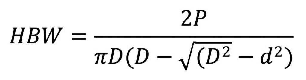
In many steelworks producing large forgings and billets, in numerous heat treatment companies, and near many factory lines producing components for safety-critical applications, you’ll find a Brinell hardness tester. These machines have been used all over the world for more than a century (the test was first demonstrated by its inventor, the Swedish metallurgist August Brinell, in 1900), determining metal hardness by means of a tungsten carbide indenter ball that leaves a dish-shaped indentation in the surface of the test material.
In the test, the material sample is placed on a rigid anvil, and the indenter descends onto it under loads ranging from 1 kg up to 3,000 kg, depending on the material. Indenters vary in diameter from 1 mm to 10 mm. Most tests use a 3,000 kg load and a 10 mm ball, and the standards always refer to this as “HBW 10/3000.” HBW stands for Hardness Brinell Wolfram, Wolfram being another name for the tungsten carbide the indenter ball is made from. After the (approximately) fifteen second indenting cycle, the indentation is measured across both its x and y axes, as a minimum, by a special calibrated microscope. The mean of the diameter readings is then fed into the Brinell equation.
Contact us with your Reader Feedback!
Naturally, most technicians would rather not use that equation, so they look the indentation diameter up on a chart and “read across” to the derived hardness.
The great advantage of the Brinell test, when considered alongside other metal hardness testing methods, is that the large indentation diameter (typically between 2.4 mm and 6 mm) means the test result is generally unaffected by the grain structure of the metal. It also means that the surface of the test sample can be adequately prepared in just a few seconds with an angle grinder. For these reasons, the test is regarded by many as the “default” one for rough-surfaced and/or coarse-grained samples.
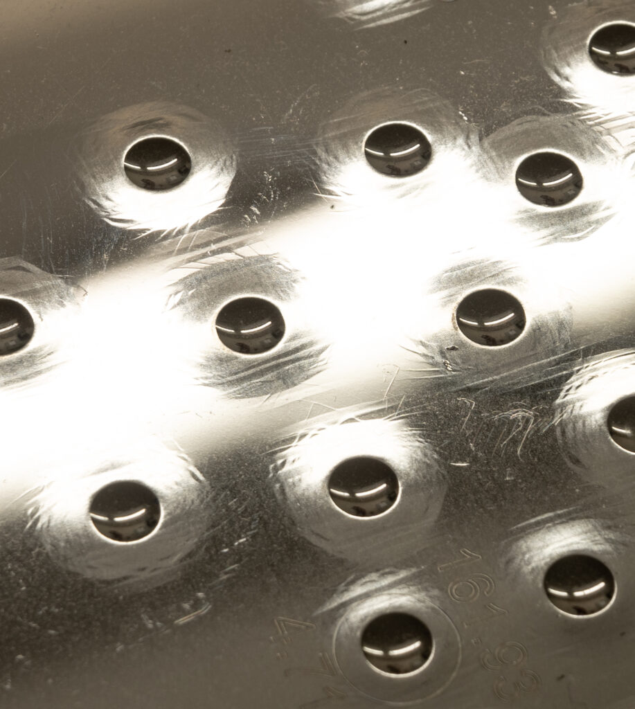
On the block in image (Figure 4), the distortion around the indentations can be seen very clearly.
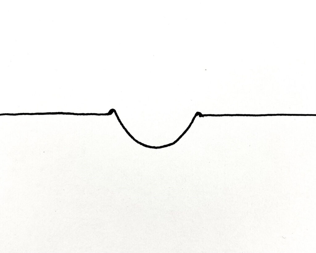
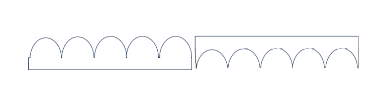
That seems pretty simple, but there are inherent weaknesses in the Brinell test: measuring the indentation. In our previous article (read it in Heat Treat Today’s August 2023 Automotive Heat Treat print edition), we used this image (Figure 2) to illustrate how difficult it could be to work out exactly where an indentation edge begins and ends.
You might look at Figure 2 and think, “I’m pretty confident about where that indentation edge is,” but it’s trickier than it looks, because the process of indenting doesn’t just push material downwards; it also spreads it sideways, and you get a “pile up” around the rim of the indentation. The pile up may be difficult to see on hard material, or there may be a subtle “lip” inside the pile up that represents the true edge, but considered in cross-section, indentations look roughly like this simple sketch above (Figure 3).
Figure 2. Measurement of Brinell hardness test indentation (Source: Foundrax Engineering Products Ltd.)Figure 3. Sketch of cross-section of indentation (Source: Foundrax Engineering Products Ltd.)
The overhead light illuminates the “pile up” rim very clearly on some of those indentations as a highlight around the edge. Where, exactly, does the pile up end and the true edge of the indentation begin? Bear in mind that 0.2 mm can equal 20 hardness points. You could show an indentation to three experienced workshop technicians and receive three different answers to the diameter question, and this problem has been a challenge of the Brinell test from its inception. Special blocks are available for training technicians in measurement, but the problem of operator interpretation was such that, in some quarters, the Brinell test was regarded as a bit “rough and ready.” “Ok for the workshop but not for the lab,” was perhaps how it was once seen.
Why Automate the Brinell?
The first question to consider when looking at the automation of the Brinell test is the measurement system because this is the inherent weakness. There are, of course, applications where only narrow tolerances are acceptable, and disagreements can arise between customers and suppliers.
Over the years, certain manufacturers, who mill heat treated materials for the oil tool industry, confided to us that they were regularly using expensive testing laboratories because of clients disputing the hardness figures of their products. They had previously been using manual microscopes. Obviously, this has reputational, as well as financial, consequences. If a manual microscope is employed on raw materials at the goods-in-process stage and there’s an error reading the hardness, you could find at final machining that you have put a lot of time and effort into a part that, in the end, is too hard or soft for the intended application.
Manually manipulating the microscope may not be worth the effort, especially when even a diligent operator may read the result incorrectly. With an automatic Brinell microscope, however, there is the possibility of major time and cost savings.
4 Levels of Automation
#1 Beginnings of Brinell Automation
The first step in automating Brinell hardness testing began 40 years ago when the world’s first automatic measurement microscope hit the market. The system, still being regularly refined, was able to measure the diameter of the indentation across over 100 axes, calculate the mean, and determine the hardness in a split second. It can handle most surface irregularity, operate in poor lighting, and warns operators of unacceptable surface preparation. Additionally, its precision adjusts for spatial error when lining up with a graticule. Within a few years of launch, a major oil tool manufacturer’s quality chief recommended its use to his suppliers, and user uptake was rapid.
#2 Integrated Microscope Model
A further step in automation is to dispense with operator handling of the microscope entirely by the acquisition of a tester with an integrated microscope. The microscope mentioned above, for example, is a feature on several hardness testing machines. The heavy-duty indenter holder pivots away from its normal line of thrust at the end of the indenting cycle, allowing a supra-mounted camera to view the indentation. This is hugely advantageous: no separate apparatus near the test machine, reduced handling time, and thus, much faster testing overall. Results from such machines are displayed next to the control panel and quickly uploadable to company quality systems.
Figure 4. Block with distortion around indentations (Source: Foundrax Engineering Products Ltd.)
#3 Dispensing of Manual Operations
Another automation option is to dispense with a hand-cranked anvil capstan and purchase a tester with a fixed anvil and movable test head. The technician is not required to manually raise and lower the anvil to allow for variations in the size of sample. Instead, the test head automatically “takes up” the space and also clamps the test piece very securely in place during the test cycle.
#4 Incorporate Custom Hardness Tester in Production Line
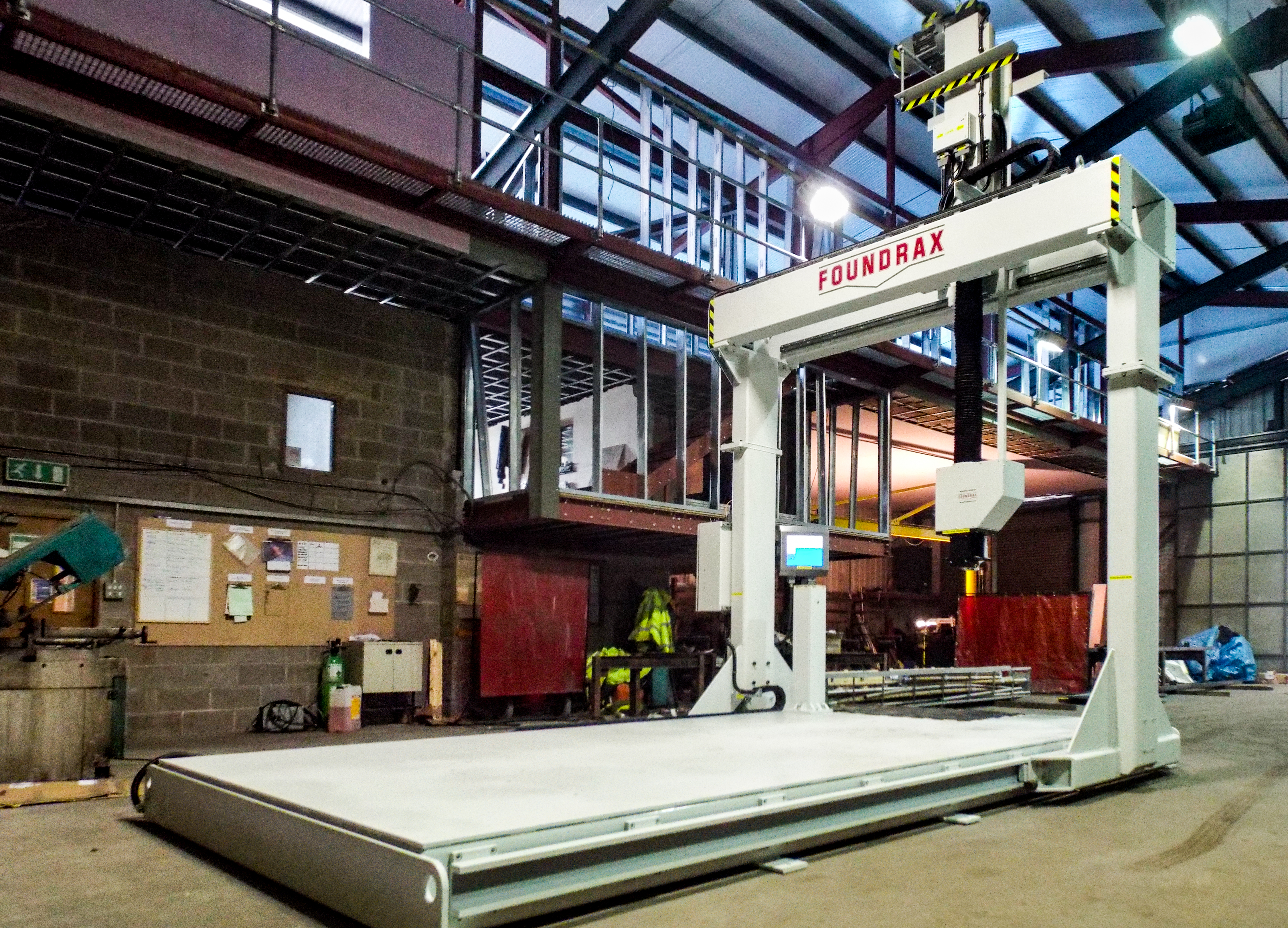
The fourth, and obviously most dramatic, automation step to consider is incorporating a custom-designed hardness tester into the production line. In some industries, this is essential. Large billets and forgings can’t be lifted into the jaws of a benchtop or floor-standing Brinell tester; so, for highly accurate testing of such items, a larger machine is required (Figure 5).
Figure 5. A custom-designed production line hardness tester. This machine is now in Texas. (Source: Foundrax Engineering Products Ltd.)
The whole gantry moves on one axis of travel while the test head moves perpendicular to that and, of course, up and down. This provides the full x, y, z movement. Large samples are maneuvered on and off by crane. The test head assembly incorporates the automatic microscope and results are displayed on a screen beside the control panel. Test results can be instantly uploaded to factory quality systems. The head assembly can also incorporate a milling tool for surface preparation!
With any decision to purchase plant and machinery equipment, some form of cost-benefit analysis is worthwhile. Clearly, if you’re doing a significant amount of business annually with a customer who is threatening to cease contracting with you because your hardness measurements are wrong too often, then the decision to buy an automatic microscope is not a difficult one. If staff are on overtime because mandatory hardness testing is adding too much time to production schedules, then a heavy-duty production machine with automatic microscope, movable test head, and sample clamp will pay for itself easily.
One thing is certain: Every automation option in Brinell testing increases accuracy and saves time.
About the Author
Alex Austin has been the managing director of Foundrax Engineering Products Ltd. since 2002. Foundrax has supplied Brinell hardness testing equipment for 60+ years and is the only company in the world to truly specialize in this field. Alex sits on the ISE/101/05 Indentation Hardness Testing Committee at the British Standards Institution. He has been part of the British delegation to the International Standards Organization advising on the development of the standard ISO 6506 “Metallic materials – Brinell hardness test” and is the chairman and convenor for the current ISO revision of the standard.
IperionX, a producer of high-quality titanium alloys, has commissioned a titanium production facility in Virginia.
Anastasios (Taso) Arima, CEO of IperionX, commented in a letter to the company’s shareholders: “Our Virginia titanium facility is designed to apply our HAMR [Hydrogen Assisted Metallothermic Reduction] and HSPT [Hydrogen Sintering & Phase Transformation] technologies to produce sustainable, high-quality and high strength titanium metal products at low cost.”
Full capacity is scheduled for 2026, with more than 1,000 metric tons of titanium produced per year. Using titanium powder produced on site, IperionX plans to employ unique forging technologies to produce titanium mill products and near net shape titanium products and to apply AM to produce 3D printed titanium products.
Arima also added, “We engaged with Lockheed Martin, GKN Aerospace, and the U.S. Army to replace traditional titanium mill products, in this case titanium plate, providing a new domestic and sustainable source to enhance their critical supply chains.” To aid these goals, Iperion is installing a large-scale, industrial furnace at their Virginia facility.
This letter to IperionX’s shareholders can be found here.
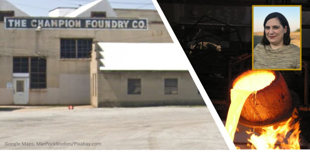
Skuld LLC announced that they had purchased the site belonging to the former Champion Foundry in Piqua, Ohio, a gray and iron foundry that had closed in March 2017. The company will continue to be focused on innovation in the metals industry, serving their clients through a number of innovations related to novel materials and manufacturing technologies.
The four buildings with nearly 32,000 square feet of space are being refurbished to be capable of casting a wide range of ferrous metals (gray, ductile iron, steels) and nonferrous metals (aluminum, brass, bronze, copper, nickel alloys). The plant will initially have 3,000 tons of capacity but plans are in place to expand to ten times that capacity in the next few years.
Skuld will be installing machining, foam blowing, a printer farm, and heat treating, adding to their current 5 small heat treat furnaces and adding to their operations, which primarily consist of lost foam casting. The new installations will aid the company as they serve the defense, tooling, and heavy equipment industries. They are also beginning to target production of heat treat fixtures and baskets.
Sarah Jordan, CEO, Skuld LLC
Production at the new site is scheduled to begin in April 2024. Sarah Jordan, CEO of Skuld LLC, commented, "Skuld is looking forward to getting our induction melting furnaces installed so that we can produce higher temperature iron, steel, and nickel alloy castings." She continued, "many [heat treaters] have custom furnace components and fixtures that require high temperature metals. These parts can have extremely long lead times, sometimes over a year, which is a problem if they are stocked out." By using their new tooling free processes, Jordan says that they can help clients drive lead times down to less than a month, if not a day for emergency spares.
Skuld is a company founded by two metallurgical engineers, Mark DeBruin and Sarah Jordan, with ties to the heat treat industry. DeBruin is the former CTO of Thermal Process Holdings. Jordan formerly worked in heat treating at Timken and Commercial Metals and was a staff engineer for Nadcap heat treat.
The full press release from Skuld LLC is available upon request.
Metal 3D additive manufacturing has grown dramatically in the last five years. Nearly every metal printed part needs to be heat treated, but this presents some challenges. This article will address some of the challenges that a heat treater faces when working with these parts.
This Technical Tuesday article, written by Mark DeBruin, metallurgical engineer and CTO of Skuld LLC, was originally published in December 2023’sMedical and Energy magazine.
Mark DeBruin Metallurgical Engineer and CTO Skuld LLC
In my experience, on average, about 10% of all 3D metal printed parts break during heat treatment; this number varies depending on the printer and the unique facility. While materials can be printed with wire or even metal foils, I’m going to mainly focus on the approximately 85% of all metal 3D printed parts that are made from metal powder and either welded or sintered together.
Most metal printed parts normally have heat added to them after printing. In addition to the heat of the printing process and wire electrical discharge machining (EDM) process to separate the part from the build plate, heat may be added up to five times. These steps are:
Burnout and sintering (for some processes such as binder jet and bound powder extrusion)
Stress relieving
Hot isostatic pressing (HIP)
Austenitizing (and quenching)
Tempering
3D printing can create a non-uniform microstructure, but it will also give properties the client does not normally desire. Heat treating makes the microstructure more uniform and can improve the properties. Please note that heat treating 3D printed parts will never cause the microstructure to match a heat treated wrought or cast microstructure. The microstructure after heat treating depends on the starting point, which is fundamentally different.
If the part is not properly sintered, there is a high chance it will break during heat treatment. It may also exhaust gases, which can damage the heat treat furnace. The off gases will recondense on the furnace walls causing the furnace to malfunction and to need repair. This can potentially cost hundreds of thousands of dollars.
During powder 3D printing, there is a wide variety of defects that can occur. These include oxide inclusions, voids, unbonded powder, or even cracks that occur due to the high stresses during printing. Even if there are not actual defects, the printing process tends to leave a highly stressed structure. All of these factors contribute to causing a print to break as the inconsistent material may have erratic properties.
In a vacuum furnace, voids can be internal and have entrapped gas. Under a vacuum, these can break. Even if something was HIP processed, the pores can open up and break. Even if they do not break and heat is applied, the metal will heat at different rates due to the entrapped gas.
Figure 1. Macroscopic view of a 3D printed surface (left) compared to machined surface (right) (Source: Skuld LLC)
There are also issues during quenching due to the differences in the surface finish. In machining, the surface is removed so there are not stress concentrators. In 3D printing, there are sharp, internal crevices that can be inherent to the process that act as natural stress risers (see Figure 1). These can also cause cracking.
When 3D printed parts break, they may just crack. This can result in oil leaking into the parts, leading to problems in subsequent steps.
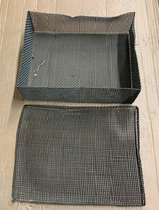
Figure 2. Example wire mesh basket (Source: Skuld LLC)
However, some parts will violently shatter. This can happen when pulling a vacuum, during ramping, or during quenching. This can also cause massive damage to the furnace or heating elements. It can potentially also injure heat treat operators.
A lot of heat treaters protect their equipment by putting the parts into a wire mesh backet (Figure 2). This protects the equipment if a piece breaks apart in the furnace, and if a piece breaks in the oil, it can be found.
Print defects in metal 3D printed parts can be a challenge to a heat treater. Clients often place blame on the heat treater when parts are damaged, even though cracking or shattering is due to problems already present in the materials as they had arrived at the heat treater. As a final piece of advice, heat treaters should use contract terms that limit their risks in these situations as well as to proactively protect their equipment and personnel.
About The Author
Mark DeBruin is a metallurgical engineer currently working as the chief technical officer at Skuld LLC. Mark has started five foundries and has worked at numerous heat treat locations in multiple countries, including being the prior CTO of Thermal Process Holdings, plant manager at Delta H Technologies, and general manager at SST Foundry Vietnam.
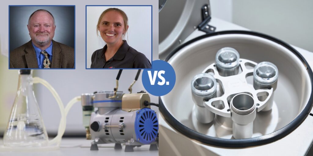
Sludge, scale, and dirt are all undesirables in quench oils that can cause detrimental effects during quenching. Bag filtration and centrifuge filtration are put to the test in this investigation. Compare the results before you make your next purchase.
This Technical Tuesday article, written by Greg Steiger, senior account manager, and Michelle Bennett, quality assurance specialist, at Idemitsu Lubricants America, was originally published in November 2023’s Vacuum Heat Treatmagazine.
Introduction
The primary role of a quench oil is to dissipate the heat from a quenched load safely, quickly, and uniformly. Both sludge and heat scale have a higher heat transfer coefficient than quench oil and dissipate heat more than this quench medium. This can affect the performance of a quench oil.
To obtain the desired metallurgical results, the operation of a quench system must be both consistent and uniform. The presence of sludge from quench oil oxidation and scale within the quench oil, pump, and heat exchangers can lead to variability in key parameters such as grain size, hardness, case depth and surface finish. The best way to minimize the detrimental effects of sludge and scale is to remove these contaminants by filtration. This article will compare the two most popular types of commercial filtration available for oil quench systems: bag filters vs. centrifuge filtrations.
This article will compare the two most popular types of commercial filtration available for oil quench systems: bag filters vs. centrifuge filtrations.
Test Methods
To simulate a two-stage bag filter, the following lab procedure was followed.
A 300-mL sample of used quench oil was passed through a 75-micron filter paper. The filtrate from the 75-micron filter was then filtered through a 25-micron filter paper. To simulate the pressure typically found in an industrial bag filter, the filtration in both the 75-micron and 25-micron papers was aided by a vacuum pump that pulled used quench oil through the filter paper.
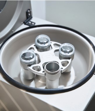
To simulate the effects of centrifugal separation, a benchtop centrifuge was used. A 300-mL sample of used quench oil was placed in a centrifuge tube and centrifuged for 25 minutes at a speed of 3,500 RPM. An additional 300-mL sample was placed in an identical centrifuge tube and centrifuged for 180 minutes at 3,500 RPM as well.
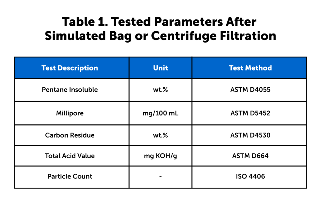
In addition to the lab testing of dirty quench oil samples, we monitored the particle count and pentane insolubles in samples from an in-use heat treating furnace. This study began with charging the furnace with clean quench oil that was filtered using a single stage 25-micron filter and collected after each filtration. At the conclusion of each timed centrifuge session, the filtrate and the centrifuged sample were tested across five tests, see Table 1.
Table 1. Tested parameters after simulated bag or centrifuge filtration (Source: Idemitsu Lubricants America) Note on Table 1: Pentane insolubles measure sludge and scale present in the quench oil after the filtration through the barrier filter or after the centrifuge. Millipore testing is a measure of the overall cleanliness of the quench oil after either filtration or centrifuging. Carbon residue testing measures the Conradson carbon in the filtered or centrifuged quench oil and is designed to determine if any of the quench speed improver additive in the quench oil has been removed via filtration or centrifuging. By measuring the total acid number (TAN) of the quench oil, it is possible to determine if the quench oil is becoming oxidized and beginning to create unwanted sludge. The ISO Particle Count tests for solids contamination, providing a quantitative value for the number of particles that are larger than 4 μm, 6 μm, and 14 μm.
Filtration Results
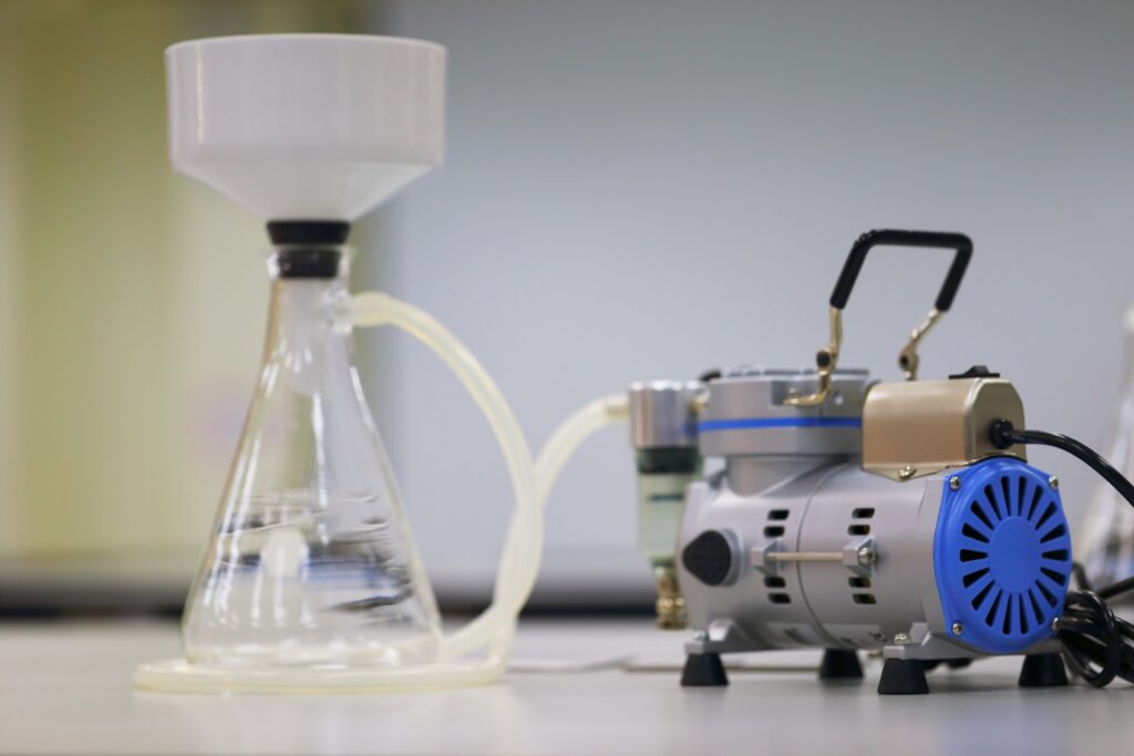
Because industrial quench oil filters are under a slight pressure, it would be very difficult to replicate this in a laboratory setting. To simulate the slight pressure found in industrial oil filters, we used a Buchner funnel connected to a vacuum pump to simulate the industrial pressure vessel. A similar setup is depicted in Figure 1.
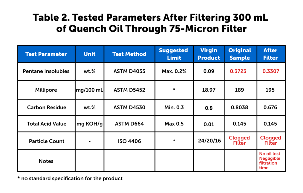
The results post-filtration are depicted in Table 2 and Table 3.
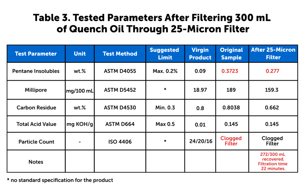
Table 2. Tested parameters after filtering 300 mL of quench oil through 75-micron filter (Source: Idemitsu Lubricants America)Table 3. Tested parameters after filtering 300 mL of quench oil through 25-micron filter (Source: Idemitsu Lubricants America)
Another popular method of filtration in a heat treating facility is through a centrifuge. While it is impractical to use a full-size industrial centrifuge in a lab, the same results can be achieved through the use of a smaller sample size and a benchtop centrifuge. A benchtop centrifuge similar to the one seen in Figure 2 was used to produce the results in Tables 4 and 5 (below).
Understanding the Test Methods: Bag/Barrier Filtration
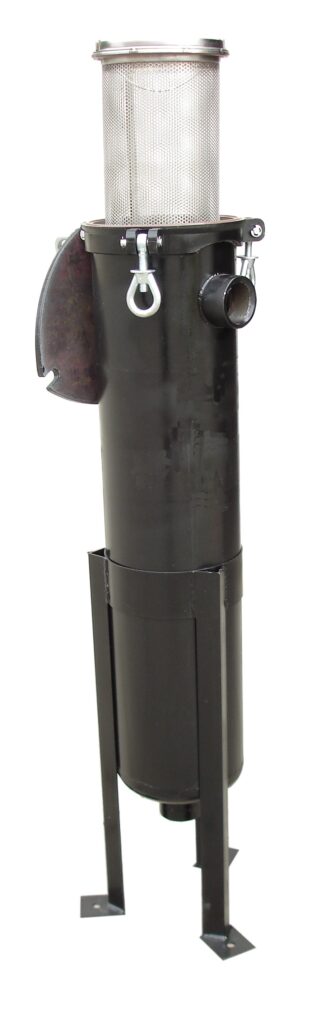
Figure 3. Polyethylene felt filter bag and filter canister (Source: SBS Corporation)
Bag (or barrier) filtration is the most common type of filtration used in quench oil filtration. For the heat treater, there are many different size filters available, as well as different configurations varying in the number of canisters and filters. The filter creates a barrier that particles greater than the pore size in the barrier cannot pass. The primary reasons for its popularity are economics, simple operation, and design. A typical polyethylene bag filter and filter cannister can be seen in Figure 3.
The most common filter sizes are 50-micron and 25-microns. Both 5-micron and 25-micron filters were used in this investigation because the test sample contained a high level of pentane insoluble. Additionally, since it is commonly thought that using a 50-micron filter will cause blinding and clogging, we chose a 75-micorn filter and a subsequent filtration step of using a 25-micron filter to simulate a common two-stage quench oil filter.
Understanding the Test Methods: Centrifuge Filtration
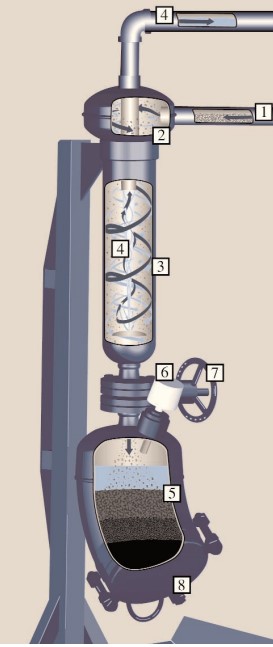
Using a centrifuge to filter out sludge and scale is also commonly used in many heat treating operations. The difference between centrifugal filtration and barrier filtration is centrifugal filtration relies on gravity, friction, and centrifugal force to separate the particles from a quench oil instead of a physical barrier (Figure 4).
Figure 4. Horizontal centrifugal filtration (Source: SBS Corporation)
In the horizontal centrifugal filtration diagram, the dirty oil enters the tangential opening (section #1) and is forced into a spinning motion. A centrifugal force (occurring in section #2) is based on the spinning pentane insolubles, scale, and any other solids contained in the dirty oil.
In section #3, the friction created by the flow of the solids, scale, and other undesirables encountering the steel body of the centrifugal separator creates a low viscosity shear layer. In section 4, the clean liquid travels through a vortex and leaves through a side discharge. The slowing velocity of the undesirables allows gravity to pull them into the debris collection area in section #5. The now cleaned oil regains its velocity and continues through the vortex created by the centrifugal forces acting on the solids to a center discharge and back to the quench tank. As the debris fills section 6, a light will illuminate, indicating the receptacle is full and needs to be emptied.
Once the undesirables fill the debris collection area, an indicator light signals the receptacle is full and a gate knife control valve (section #7), is manually closed so the debris collector can be opened via the closure (section #8).
Discussion
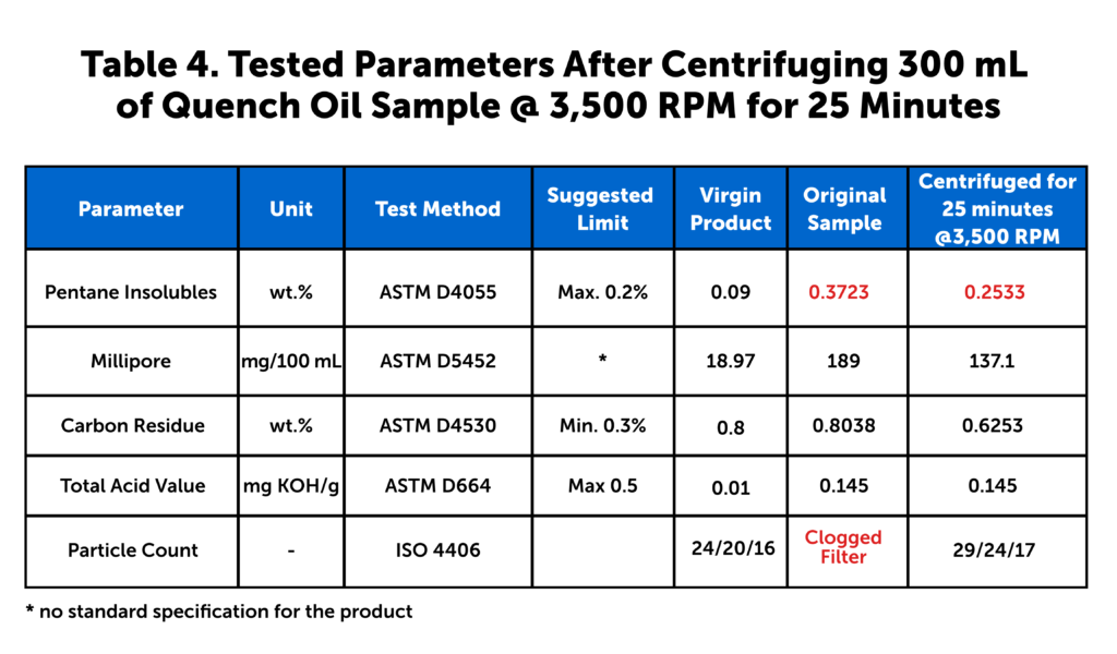
Table 4. Tested parameters after centrifuging 300 mL of quench oil sample @ 3,500 RPM for 25 minutes
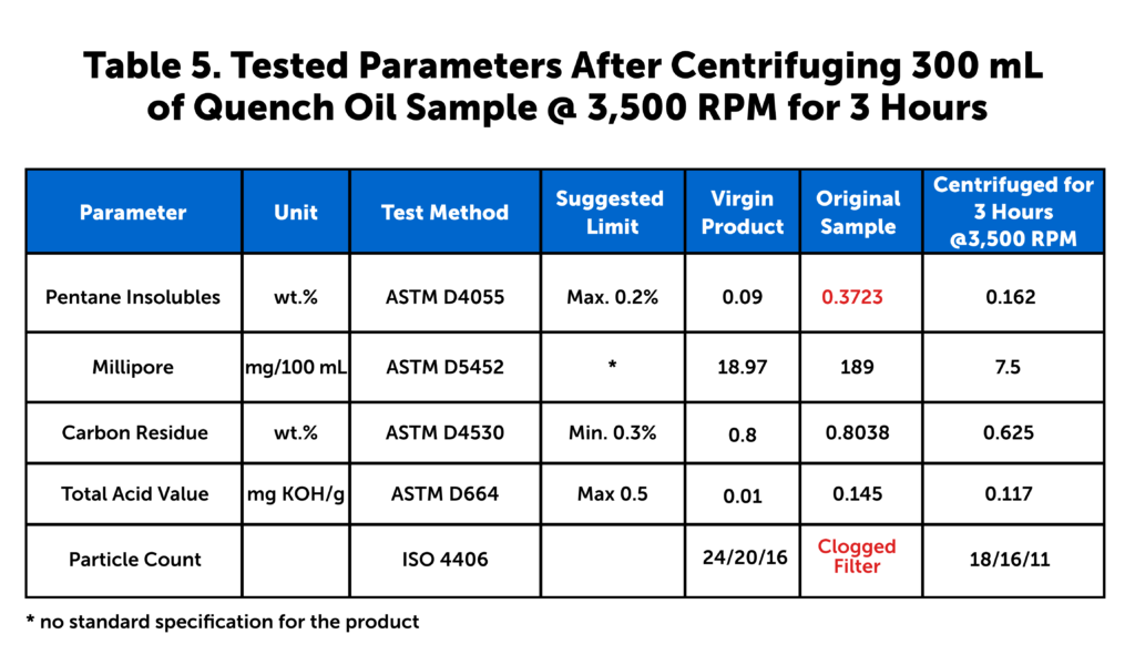
(Source: Idemitsu Lubricants America)Table 5. Tested parameters after centrifuging 300 mL of quench oil sample @ 3,500 RPM for 3 hours
(Source: Idemitsu Lubricants America)
As seen in Tables 2 and 3, filtration does improve the overall cleanliness of the dirty quench oil. The weight percent of the pentane insolubles showed a significant improvement when filtered through the 25-micron fi lter. However, the level of pentane insolubles was still outside of the suggested limits for the quench oil.
This was not seen when the quench oil was filtered through a 75-micron filter. The 75-micron filter had little or no effect on the Millipore results. The Millipore results increased when filtered through a 75-micron filter. This leads us to believe some of the particles within the dirty oil were forced through the 75-micron filter and not through the 25-micron filter, as the 25-micron filter showed an improvement in Millipore results.
An ISO particle count was not possible on the original used samples or the filtered samples because the filter clogged on all three test samples.
The largest difference in results lies in the carbon residue testing. The level of carbon residue is essentially the same after both the 75-micron and 25-micron filter samples. Both of the carbon residue levels are within the normal suggested limits. However, the high level of sludge in the original dirty sample is likely removing some of the quench speed improver from the quench oil. The removal of the quench speed improver changes the performance of the quench oil over time.
In examining the results of the centrifuge testing in Tables 4 and 5, it is clear centrifuging for 25 minutes has better effect on the cleanliness of the oil sample than filtering through a 25-micron filter. The level of pentane insolubles after centrifuging for 25 minutes at 3,500 RPM is still outside of the suggested limit. However, running the centrifuge for three hours under the same conditions not only brings the pentane insolubles within the suggested limits, the Millipore and particle counts also see an improvement over the virgin oil sample results. The carbon residue levels behave much the same as they do in the filtration tests.
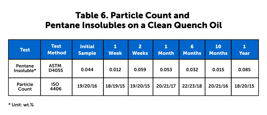
What is significant is the year-long study we conducted using actual customer data. In this study, a furnace was dumped, cleaned, and then filled with clean virgin oil. The authors then tested the ISO particle counts and pentane insolubles for one year after the furnace was charged with clean oil. These results are seen in Table 6. These data show essentially no change in the particle counts and a slight improvement in the level of pentane insolubles over the one-year period.
Table 6. Particle count and pentane insolubles on a clean quench oil (Source: Idemitsu Lubricants America)
Conclusion
From the testing conducted, it is clear the filtration through a 75-micron filter has little to no effect upon the tested parameters and the performance of the quench oil. The high levels of pentane insolubles will likely clog heat exchangers, pumps, and valves within the quench system. The dirty oil will also likely cause metallurgical issues such as isolated soft spots due to the slower heat transfer of the dirty oil. The results of filtering a dirty oil through a 25-micron filter show some improvement in the pentane insoluble levels. However, the result is still outside of the recommended limits for the oil. Additionally, the ISO particle counts were not able to be tested due to the overall dirty condition of the filtered sample.
In contrast to the bag filter samples, the centrifuge samples showed a marked improvement over the dirty sample. While the pentane insoluble level was slightly out of the recommended limit for the 25-minute centrifuge sample, all results were within the recommended specifications for the three-hour centrifuge sample. In some cases, such as the particle count, the centrifuge sample had better results than the virgin sample.
While the centrifuge and filter results both show how hard it is to effectively clean a dirty quench oil, the results from the year-long study show very little difference in particle counts and a slight decrease in pentane insolubles, which can be explained through the normal addition of virgin make up oil to the quench system.
It is clear both centrifuge separation and bag filtration can improve the overall condition of a dirty quench oil. However, if your level of dirt, sludge, and scale reaches near the levels of the tested sample, a centrifuge is better at removing these than filtration. Overall, the data show the most important and efficient method is to begin filtering a clean quench oil as soon as the quench tank is charged.
About The Authors
Greg Steiger is the senior account manager at Idemitsu Lubricants America. Previous to this position, Steiger served in a variety of technical service, research and development, and sales and marketing roles for Chemtool Incorporated, Witco Chemical Company, Inc., D.A. Stuart Company, and Safety-Kleen, Inc. He obtained a BS in Chemistry from the University of Illinois at Chicago and recently earned a master’s degree in Materials Engineering at Auburn University. He is also a member of ASM International.
Michelle Bennett is the quality assurance specialist at Idemitsu Lubricants America, supervising the company’s I-LAS used oil analysis program. Over the past 12 years, she has worked in the quality control lab and the research and development department. Her bachelor’s degree is in Chemistry from Indiana University. Michelle is a recipient of Heat Treat Today’s 40 Under 40 Class of 2023 award.