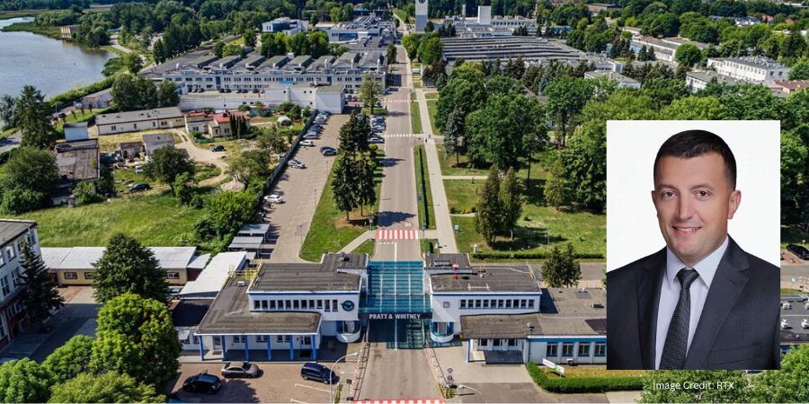
RTX’sPratt & Whitney, a North American aerospace manufacturer headquartered in East Hartford, Connecticut, is investing $100 million to expand production capacity through advanced manufacturing processes, including heat treatment of forged engine components, to support increased output of commercial and military aircraft engines. The expansion is expected to strengthen supply for aerospace programs and improve throughput of critical engine parts used across global aviation fleets.
The investment will be made at the company’s facility in Rzeszów, Poland, where operations will be expanded to include additional processing capabilities and production capacity. The site supports manufacturing for several engine programs. including GTF™, F135, and F100 platforms, which serve both commercial aviation and defense applications.
Piotr Owsicki General Manager Pratt & Whitney Rzeszów
The expansion is intended to address growing global demand for aircraft engines and related components. “This investment reflects our continued commitment to increase production capacity for our [clients] and deliver more, faster,” said Piotr Owsicki, general manager of Pratt & Whitney Rzeszów. The capital project, expected to be fully operational by 2028, will enable a 30% increase in output of critical engine parts such as rotating compressor and turbine disks.
Press release is available in its original form here.
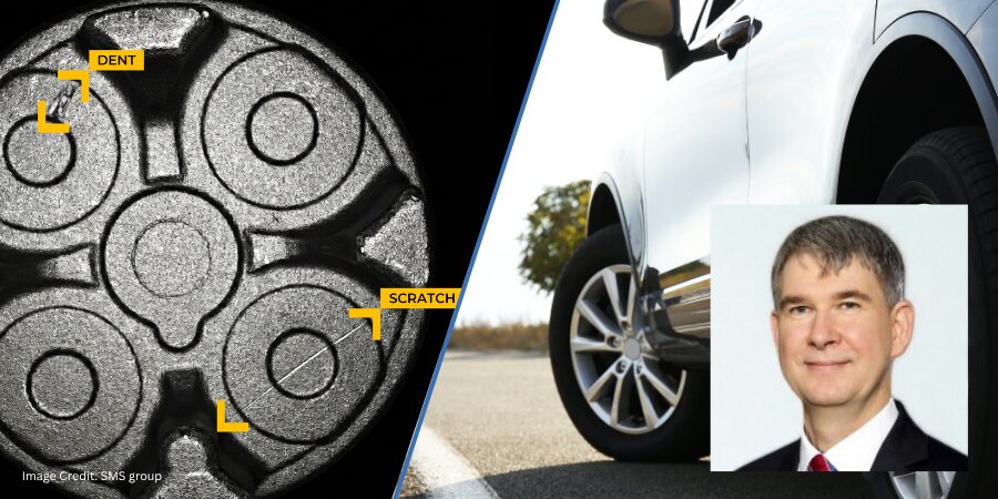
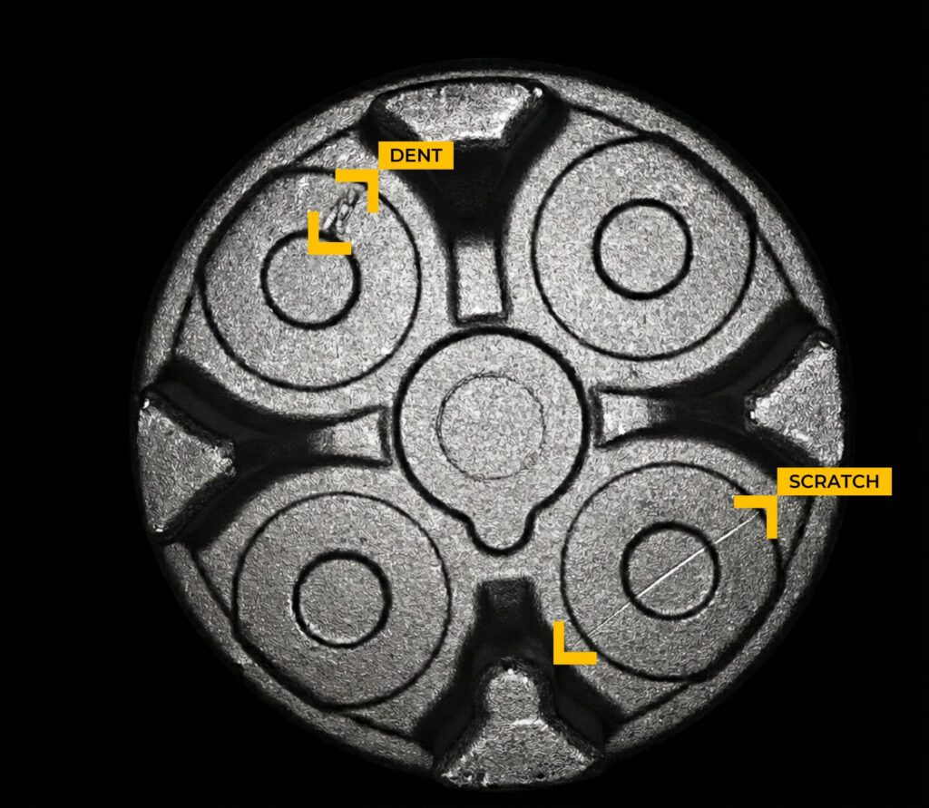
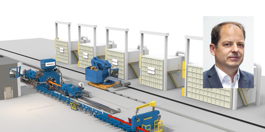
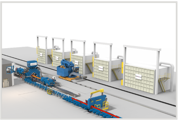
Hirschvogel is implementing automated inspection of closed-die forgings to replace manual visual checks, enabling faster detection of surface defects and dimensional deviations in automotive components. The approach supports more consistent quality outcomes in forged parts while reducing error rates and scrap in high-volume production environments.
Working in partnership with SMS group, a global supplier of materials industry technology with North American headquarters in Pittsburgh, Pennsylvania, Hirschvogel, a global automotive supplier specializing in solid metal forming, has deployed an automated final inspection system for closed-die-forged components at its Denklingen, Germany, facility. The system replaces an existing manual testing station with a fully digital process designed to evaluate each component in seconds.
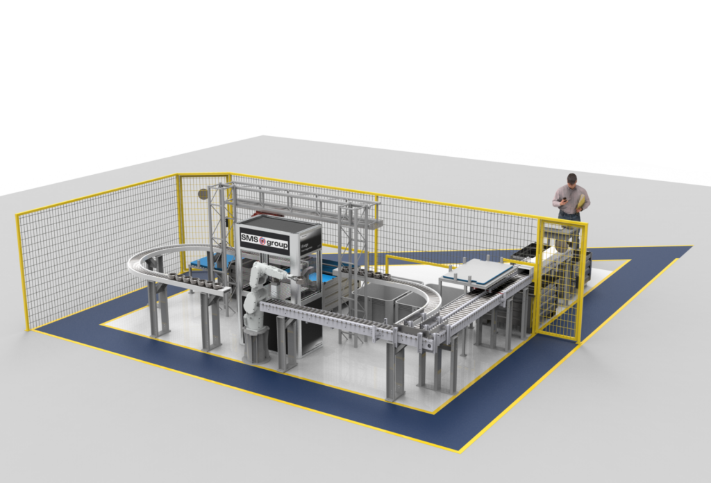
3D rendering of the test station: Visualization of the automated final inspection for closed-die-forged automotive components. | Image Credit: SMS groupThe automated final inspection allows various types of closed-die forging defects to be identified and categorized (example shown). | Image Credit: SMS group
The inspection solution integrates automated handling and high-resolution imaging to assess surface conditions and geometry. A robot moves forgings directly from transport containers, while camera sensors capture images that are analyzed in fractions of a second. Detected defects are classified against a digital catalog, reducing the likelihoos of misclassification and minimizing pseudo-scrap, or the disposal of acceptable parts.
The system was developed in cooperation with image processing specialist Sightwise as well. As part of SMS group’s iForge digitalization platform, the inspection is designed to integrate into forging production lines and support automated quality assurance workflows.
Axel Rossbach Forging Technology Expert SMS group
A key feature of the system is its use of synthetic training data to develop inspection models. Instead of relying on physical samples of defective parts, the system uses CAD and 3D model data to simulate material properties, surface textures, and defect types. This allows analysis models to be prepared within hours rather than weeks.
“The new system enables us to speed up the final inspection significantly and ensure maximum process stability in the line itself,” said Axel Rossbach, forging technology expert at SMS group. The scalable system can also be adapted to new product variants, supporting production flexibility in automotive forging operations.
Press release is available in its original form here.
Linamar Corporation, a North American manufacturer with in-house heat treating capabilities, has acquired select assets of Winning BLW, strengthening its capabilities in warm forging and precision gear manufacturing for automotive and industrial applications. The acquisition supports production of bevel and helical gears, components that typically require controlled heat treating to achieve the hardness, wear resistance, and fatigue strength needed for drivetrain systems.
The facilities included in the transaction are located in Remscheid and Penzberg, Germany, bringing established expertise in forging and gear production into Linamar’s global manufacturing network. The Remscheid facility handles mass production of high-performance precision bevel and intermediate gears for light vehicle market, while the Penzberg facility specializes in helical gears and high-precision components serving the commercial and off-highway sectors. Through these acquisitions, Linamar expands its offering of precision bevel and helical gears, as well as small- to medium-sized drivetrain and transmission components.
Jim Jarrell CEO and President Linamar Corporation
“These acquisitions are a great strategic fit for Linamar. They strengthen our technology and manufacturing capabilities in products where we are already strong, deepen relationships with key global [clients], and position us for continued growth by increasing our content per vehicle across multiple markets,” said Jim Jarrell, CEO and president of Linamar.
The additions strengthen Linamar’s position in designed and machined gears, deepen its forging capabilities, and support its vertically integrated manufacturing approach.
Press release is available in its original form here.
We’re celebrating getting to the “fringe” of the weekend with a Heat TreatFringe Fridayinstallment: a private equity firm in the aerospace supply chain has acquired Forged Solutions Group, a manufacturer of high-specification forgings used in flight-critical engine and structural components. The company’s products, including aeroengine discs and shafts, are the kinds of advanced alloy components that typically move through multiple downstream heat treatment steps before entering service.
While not exactly heat treat, “Fringe Friday” deals with interesting developments in one of our key markets: aerospace, automotive, medical, energy, or general manufacturing.
J.F. Lehman & Company has completed the acquisition of Forged Solutions Group, a manufacturer of high-specification closed-die forgings for aerospace, defense, and space applications. The company produces components including aeroengine discs, shafts, and structural parts from advanced alloys such as titanium, nickel-based superalloys, steel and aluminum before moving through machining and materials testing as part of the production process.
Ben Hatcher Managing Director J.F. Lehman & Company
The company supplies components for commercial aerospace and defense platforms through its manufacturing facilities. J.F. Lehman & Company, a private equity firm focused on aerospace, defense, maritime, government, and environmental sectors, completed the acquisition as part of its strategy to invest in companies supporting critical industrial supply chains.
Ben Hatcher, managing director at J.F. Lehman & Company, said, “FSG’s expansive forging capabilities, diverse product portfolio, and meaningful available capacity form a compelling and critical solution to the broader aerospace and defense industry’s production requirements. We are excited to build upon FSG’s differentiated technical capabilities and scaled operational footprint to increase throughput in support of current and next-generation aeroengine and defense platforms.”
Press release is available in its original form here.
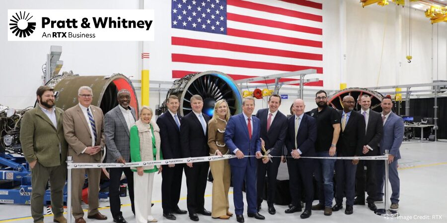
Pratt & Whitney, an RTX business, is investing $200 million to expand manufacturing at its Columbus, Georgia, site with the addition of a seventh isothermal forging press. The equipment, which will support production of rotating compressor and turbine disks for commercial and military jet engines, is expected to be operational in 2028 and is projected to increase output of these critical components by about 30 percent.
The funding will expand operations at the Columbus Forge facility, where compressor airfoils and high-strength disk components are manufactured for the company’s commercial and military engine platforms. The site is part of the broader Columbus campus that also includes the Columbus Engine Center, where maintenance, repair, and overhaul (MRO) work is performed on engines like the PW1100G-JM, V2500, PW2000, F117, and F100.
Shane Eddy President Pratt & Whitney
The latest investment at the Columbus Forge facility follows an 81,000-square-foot GTF MRO expansion at Pratt & Whitney’s Columbus Engine Center, located on the same campus. This expansion added advanced equipment and machinery that aligned with the company’s Industry 4.0 strategy. The facility’s annual capacity increased by more than 25%, adding critical overhaul volume to the GTF MRO network in support of the growing fleet.
The Columbus complex has grown from a small manufacturing facility to a manufacturing and overhaul center that now employs 2,600 people. “Since 2008, we have invested more than $1 billion to continue expanding the footprint and capabilities of our Columbus facility. This latest investment will increase output of critical parts for our growing military and commercial engine programs and underscores our ongoing commitment to ramp industrial capacity to support our [clients],” said Shane Eddy, president of Pratt & Whitney.
Press release is available in its original form here. Main image shows Pratt & Whitney President Shane Eddy joined with Georgia Governor Brian Kemp and other company, state, and local leaders to celebrate two major expansions of Pratt & Whitney’s Columbus, Georgia facility on February 24, 2026.
Century Aluminum Company has emphasized that next-generation EX smelting technology will be critical to the development of its new primary aluminum smelter, one of the most advanced technologies deployed in the U.S. This platform is designed to improve productivity, reduce energy consumption per ton, and lower emissions, reinforcing both economic competitiveness and environmental performance in primary aluminum manufacturing.
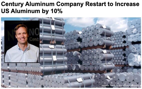
Click on the image above to read more about Century Aluminum’s recent restart to boost U.S. production by 10%.
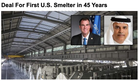
Planned for Inola, Oklahoma, at the Tulsa Port of Inola industrial park, the proposed facility is expected to produce up to 750,000 metric tons of primary aluminum annually, more than doubling current U.S. smelting capacity once fully operational. Century Aluminum will partner with Emirates Global Aluminum (EGA) on the project, with EGA contributing its proprietary EX smelting technology and holding a majority ownership stake, while Century Aluminum provides operational expertise and leadership in the U.S.-based aluminum production. The project aims to strengthen material availability for downstream manufacturers serving automotive, aerospace, energy, and defense markets.
Jesse Gary Chief Executive Officer Century Aluminum Company
“Our partner EGA brings world-class smelting technology and construction expertise that are fast-tracking our collective efforts to realize a new era of domestic primary aluminum production,” said Jesse Gary, chief executive officer of Century Aluminum Company. “This expanded production will benefit critical U.S. industries and create thousands of American manufacturing jobs, reinforcing the vital role of aluminum in national defense and economic vitality.”
EX technology is EGA’s next-generation smelting platform, featuring reduction cells that provide higher productivity per square meter than EGA’s previous DX+ Ultra technology. The cells are larger and have improved current efficiency, enabling greater aluminum production from each smelting cell. The technology supports more cost-effective aluminum production with lower emissions intensity, reinforcing the project’s operational and environmental goals.
For background on the initial announcement of this historic smelter project, click on the image above for our May coverage.
The use of EX technology also positions the project within the broader global landscape of aluminum smelting innovation, strengthening its appeal as an alternative source of advanced smelting capability at a time when governments and manufacturers are increasingly focused on supply chain resilience, domestic capacity, and technology diversification. EGA’s own communications highlight EX as a key step toward large-scale industrialization and a foundation for future growth as a smelting technology provider of choice in the global aluminum industry.
Construction is expected to begin as early as 2026, with commercial production anticipated before the end of the decade. Once completed, the facility is expected to support approximately 1,000 permanent direct jobs and support roughly 4,000 construction roles, while helping reduce reliance on imported aluminum and reinforcing domestic manufacturing capabilities. Industry leaders have described the project as a critical step toward rebuilding U.S. primary aluminum production and supporting long-term supply stability for North American manufacturers.
Press release is available in its original form here.Additional information comes from EGA’s June 2025 press release here.
Haynes International Inc., has commissioned a new hydraulic radial forging line to increase its production of nickel- and cobalt-based alloys, serving markets such as aerospace and chemical processing in the United States. The integrated plant investment, which includes a forging machine, reheating and annealing systems, and automated material handling, is expected to improve production efficiency, metallurgical quality, and responsiveness to global demand while supporting growth in high-performance alloy manufacturing.
Slated for completion in 2027, the project features the SMX 800 / 25 MN hydraulic radial forging machine with a combined total pressing force of 100 MN, enabling direct conversion of ingots into billets and bars tailored for critical applications. The new line also incorporates cutting, loading, unloading, and bar finishing equipment to create a fully integrated solution that boosts throughput and supports advanced alloy processing.
Visualization of a radial forging line from SMS group, similar to the one to be installed at Haynes International’s Kokomo site in Indiana Source: SMS groupThomas Winterfeldt Head of Forging Plants SMS group
Supplied by SMS group, the radial forging line includes modern reheating and annealing furnaces designed to meet rigorous AMS 2750 temperature uniformity and tolerance standards, low-NOx burners to help maintain emissions below applicable environmental limits, and an integrated control system to manage production sequences with minimal operator intervention. Software tools, including Comforge®, will help optimize forging strategies based on real-time material behavior to improve yield and consistency.
At the core of the new capability is energy-efficient hydraulic technology that reduces installed electrical power requirements by roughly 50 percent while maintaining constant pressing force and precise process control. These features enable Haynes to deliver high-performance alloy products more efficiently while maintaining metallurgical quality to serve expanding needs in aerospace and other advanced industrial sectors.
Thomas Winterfeldt, head of forging plants at SMS group, said the project reflects a continued focus on pushing the limits of capability and efficiency in forging technology to meet material requirements in aerospace applications.
Press release is available in its original form here.
Ryerson Holding Corporation, a value-added processor and distributor of industrial metals, and Olympic Steel, Inc., a U.S. metals service center, announced that they have entered into a definitive agreement to merge. The merger will enhance the combined company’s presence as the second-largest North American metals service center and will bring Olympic Steel’s complementary footprint, tempering capabilities, and heat treated product offerings into Ryerson’s network of value-added service centers.
The deal is expected to generate approximately $120 million in annual synergies by the end of year two via procurement scale, efficiency gains, commercial enhancement, and network optimization. The merger adds Olympic Steel’s thermal processing services and metals to Ryerson’s existing offerings.
As part of the transaction, Michael D. Siegal, executive chairman of Olympic Steel’s Board of Directors, will be appointed chairman of the Board of Directors (“Board”) of the combined company and Olympic Steel will also appoint three other directors to the combined 11-member Board. Eddie Lehner, president and chief executive officer (“CEO”) of Ryerson, will serve as CEO of the combined company, with Richard T. Marabito, CEO of Olympic Steel, serving as president and chief operating officer.
Eddie Lehner said, “This merger represents an immensely attractive and unique opportunity for Ryerson and Olympic Steel as it combines our two organizations, which couldn’t be more complementary and synergistic around the products, services, footprint, and customer experience…The combination of our organizations will further scale the digital investments that Ryerson has made to bring Olympic Steel’s capabilities and formidable expertise into a larger network and provide our customers with greater network density, faster lead times, and a wider array of custom solutions from pick-pack-and-ship to finished parts…I look forward to working with Rick and the entire Olympic Steel organization with shared mission, passion, and purpose to unite our teams in reaching our vast potential together.”
“We are very excited about the combination of Ryerson and Olympic Steel and the trajectory of the business going forward,” added Steve Larson, chairman of Ryerson’s Board. “We look forward to welcoming Michael and the additional Olympic directors to the already strong Ryerson board. They bring a wealth of experience and perspective.”
Michael Siegal added, “This is a significant milestone for the business my father and uncle started more than 70 years ago. We went from private to public in 1994, and now we enthusiastically take this next step to accelerate Olympic Steel’s continued growth.”
Press release is available in its original form here.
We’re celebrating getting to the “fringe” of the weekend with a Heat TreatFringe Friday installment: a project that revolutionizes domestic steel making. Learn more about this green steel tech that plans to turn into a 500,000-tonne per year production micro-mill!
While not exactly heat treat, “Fringe Friday” deals with interesting developments in one of our key markets: aerospace, automotive, medical, energy, or general manufacturing.
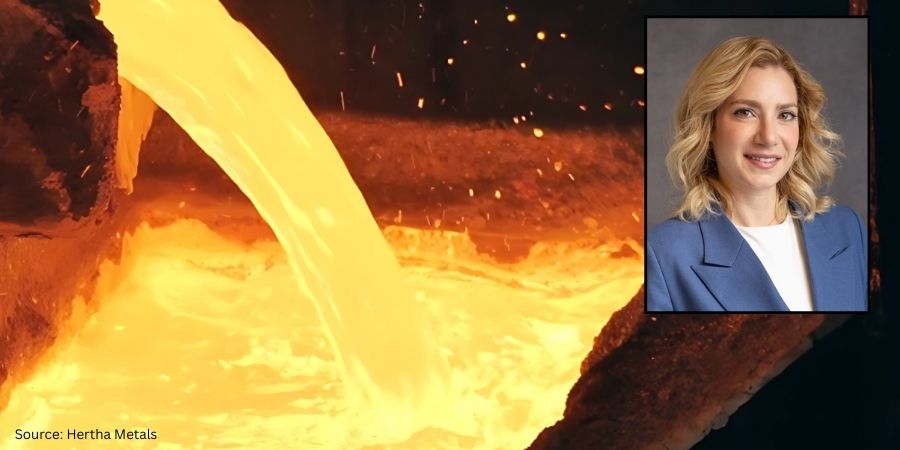
Hertha Metals has founded a technology with the potential to transform domestic steelmaking. The company’s proprietary technology is powered by natural gas, hydrogen, and electricity, enabling steel production from any grade of iron ore or waste oxide, in any format, including fines and lumps. Hertha’s process has been demonstrated at a continuous 1 tonne-per-day scale at their Conroe, TX facility, with plans to scale up to 9,000-tonnes, before launching a 500,000-tonne per year micro-mill.
This semi-continuous, single-step process delivers tunable iron and steelmaking. With Flex-HERS™, the proprietary technology, Hertha Metals can tap into domestic iron ore resources and produce low-emission steel using abundant natural gas. As clean hydrogen becomes more available and affordable, they plan to switch fuels — without changing the furnace, to remove the loss of stranded assets, and future-proof a path for steel production.
Hertha Metals steel production Source: Hertha Metals
The new technology:
Enables iron and steel production from low-grade ore, fines and waste oxides
Single-step production using abundant natural gas or clean hydrogen
Scalable technology to serve multiple markets
High-performance steel alloys under development
Laureen Meroueh CEO & Founder Hertha Metals Source:Linkedin
“After three short years of heads-down building, Hertha Metals is ready to show the world what we have achieved. After more than 300 years of coal-based primary steelmaking, Hertha Metals is introducing a process that is more energy efficient, more cost competitive, and more flexible with feedstock quality.
“The team at Hertha has been hard at work, developing and scaling our single-step ore-to-steelmaking technology. We have demonstrated our technology with various ore qualities and format (including fines) at a scale of 1 tonne per day of continuous clean steel production. This is the largest novel steelmaking pilot plant demonstration in the US and I am so proud of the speed at which we got here,” said CEO and founder, Laureen Meroueh.
Heat Treat Today original press release, last updated on 09/05/2025 at 5:15am.
In today’s News from Abroad installment, we highlight an electrically heated aging furnace for aluminum production, an electric arc furnace as part of a £1.25 billion ($1.69 billion USD) transformation, a new electric arc furnace world record, and more!
Heat TreatTodaypartners with two international publications to deliver the latest news, tech tips, and cutting-edge articles that will serve our audience — manufacturers with in-house heat treat. Furnaces International, a Quartz Business Media publication, primarily serves the English-speaking globe, and heat processing, a Vulkan-Verlag GmbH publication, serves mostly the European and Asian heat treat markets.
The commission comes as part of the company’s strategy to increase the production of high value aluminium. Source: Furnaces International
“ALRO, one of the largest vertically integrated aluminium producers in Europe by production capacity, announces the commissioning of an electrically heated aging furnace.
“This follows a total investment of 11.5 million RON (Romanian new leu) into the project. The commission comes as part of the company’s strategy to increase the production of high value aluminium.
“The CEO of ALRO, Marin Cilianu, stated: ‘By replacing natural gas with electricity, this equipment not only brings added precision and efficiency to our production processes, but also aligns with our firm commitment to sustainable development.'”
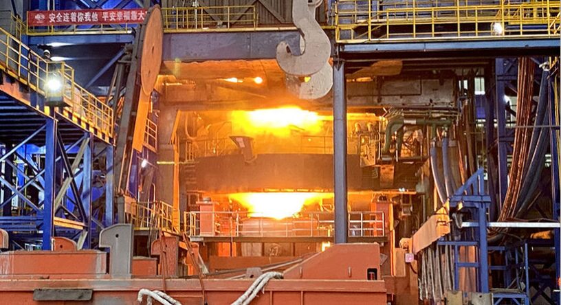
Tata Steel’s Port Talbot EAF will reduce carbon emissions by an estimated 90%. Source: Furnaces International
“Tata Steel UK launch the construction of its electric arc furnace (EAF) facility in Port Talbot, South Wales. This is part of a £1.25 billion transformation to low CO2 steelmaking, supported by a £500 million investment from the UK Government.
“To mark the construction, Chairman of the Tata Group, Mr. Natarajan Chandrasekaran, was joined at the ceremony this week by Tata Steel CEO and Managing Director, T. V. Narendran, and Tata Steel UK CEO, Rajesh Nair, as well as government ministers.
“Mr. Chandrasekaran stated: ‘This is an important day for Tata Group, Tata Steel and for the UK. Today’s groundbreaking marks not just the beginning of a new Electric Arc Furnace, but a new era for sustainable manufacturing in Britain. At Port Talbot, we are building the foundations of a cleaner, greener future, supporting jobs, driving innovation, and demonstrating our commitment to responsible industry leadership.’”
EAFs set world record in China. Source: Furnaces International
“Two EAF Quantum electric arc furnaces (EAF) from Primetals Technologies have set a world record after achieving up to 50 heats per day. The furnaces are located at the Hubei Shunle site in Hubei Province, China.
“Figures by Primetals show that on top of achieving 48 to 50 heats a day, both EAFs can record tap-to-tap times of less than 28 minutes and have power-on and power-off times of 25 and 3 minutes respectively.”
ABP CEO Till Schreiter attends the anniversary celebration of ABP Induction. Source: ABP Induction Systems GmbH
“ABP Induction celebrated its 20th anniversary with an official ceremony: On November 1, 2005, the company was spun off from the ABB Group and started into a new future as an independent company…
“Heike Marzen, managing director of the Dortmund Economic Development Agency, praised ABP Induction as an important pillar of Dortmund’s economy. She emphasized that over the past two decades, the company…impressively demonstrated its ‘Innovative strength, commitment and sustainable development.’ Many of those present had followed the company’s development.
“Heike Marzen emphasized that ABP Induction, as ‘one of the world’s leading manufacturers of induction melts, heating systems and aftermarket services,’ is a valuable partner for Dortmund. She was particularly impressed by the innovative technologies and tailor-made solutions that ABP uses worldwide.”
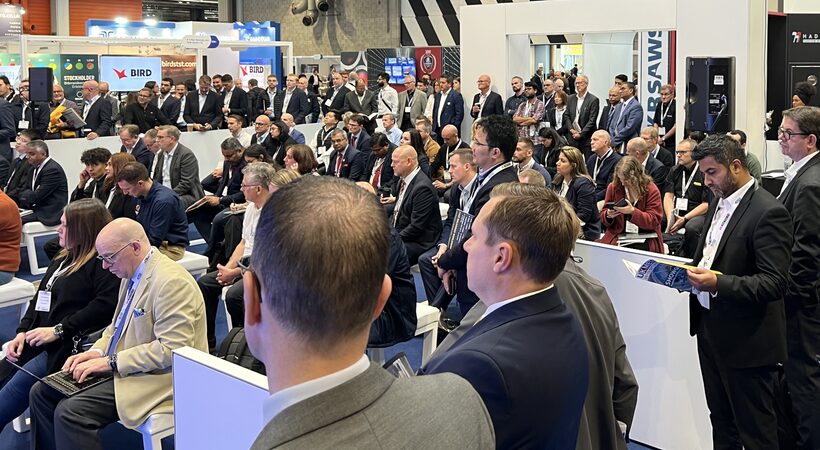
The event will include 320 exhibitors and have speakers from companies such as ALFED and Hydro Aluminium. Source: Furnaces International
“UK Metals Expo returns on 10 and 11 September 2025 at the NEC Birmingham, uniting the entire metals supply chain with the manufacturing and engineering community.
“Launched in 2022, UK Metals Expo is the essential meeting place for fabricators, stockists, production specialists, procurement teams, engineers, researchers, manufacturers, and policymakers. It’s where the industry comes together to collaborate, share ideas, and do business in a welcoming, engaging environment.
“At UK Metals Expo 2025, you can meet face-to-face with leading suppliers and top technical experts ready to tackle your project challenges and deliver tailored solutions. Expect live machinery demos, automation, robotics, and AI-powered technology, plus cutting-edge materials, coatings, and processing systems.”
The BMWE is implementing important requirements of the immediate action programme. Source: Adobe Stock
“On August 6, the German Federal Government launched six projects of the Federal Ministry of Economics. In doing so, the BMWE is implementing important requirements of the immediate action programme.
“In addition to the Carbon Dioxide Storage Act and the simplification of public procurement law, four important energy projects were launched and companies and citizens were relieved.”