Consider the numerous systems in your heat treat operations. What makes up the anatomy of each furnace or system? In this “Anatomy of a . . .” series, industry experts indicate the main features of a specific heat treat system. In this feature, the full-page spread identifies main features of induction coils.
The mark-ups for these reference images are provided by John Gadus, design and sales specialist, Induction Tooling, Inc.
View the full graphics by clicking the image below.
This Technical Tuesday article is drawn from Heat Treat Today’sApril/May 2024 Sustainable Heat Treat Technologiesprint edition, that had a special focus on green heat treat technologies.
Search www.heattreatbuyersguide.com for a list of induction equipment providers to the North American market. If you are an induction equipment supplier and are not listed here, please let us know at editor@heattreattoday.com.
This series will continue in subsequent editions of Heat Treat Today’sprint publications. Stay tuned!
Find Heat Treating Products And Services When You Search On Heat Treat Buyers Guide.Com
A nitriding service provider in Brazil will increase their production line with a single-chamber vacuum furnace from a manufacturer with North American locations.
Peter Lutz, president of Nitrion do Brasil says, “We were looking for a solution that would help not only increase our metal processing capabilities, but also efficiency and effectiveness.”
The SECO/WARWICK Vector vacuum furnace will operate in a new production hall and will handle Nitrion do Brasil’s increasing order volume. This order is a result of cooperation between SECO/WARWICK and their strategic partner in Brazil, Combustol.
Maciej Korecki Vice President of Business of the Vacuum Furnace Segment SECO/WARWICK
“Combustol supports SECO/WARWICK not only in sales but also in service activities and the supply of spare parts. Such a partner in such a remote location is a huge advantage,” commented Maciej Korecki, VP of the Vacuum Furnaces Segment in the SECO/WARWICK Group. He added, “[Nitrion do Brasil] bought a furnace that we could deliver quickly.”
The furnace on order will solve the commercial heat treater’s problem of hardening larger elements, because the furnace is equipped with a large working space. This will affect the process economics (energy savings and the graphite chamber’s increased efficiency) as well as the process cleanliness and speed. The furnace is equipped with convection heating – a system that improves the heat transfer efficiency when heating at lower temperatures, as well as directional cooling, which allows the system to efficiently cool parts with problematic shapes in various ways.
We’re celebrating getting to the “fringe” of the weekend with a Heat Treat Fringe Friday a press release detailing how additive manufacturing continues to move into the metals manufacturing industry.
While not exactly heat treat, “Fringe Friday” deals with interesting developments in one of our key markets: aerospace, automotive, medical, energy, or general manufacturing.
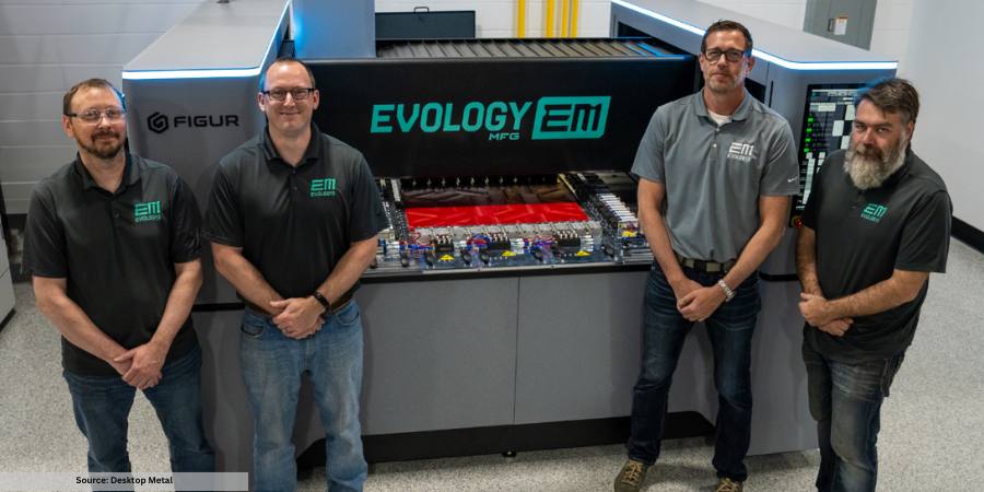
Desktop Metal, a global company at the forefront of additive manufacturing 2.0 technologies for mass production, announced that it has installed four Figur G15 Pro systems featuring digital sheet forming (DSF) technology to three manufacturers, including Evology Manufacturing in Waukesha, Wisconsin.
With 30+ years as a contract manufacturer, Evology has a full suite of both traditional and additive technologies to service companies in a wide range of industries, including aerospace, defense, automotive, agricultural, marine, mining, medical, electronics, and consumer goods. Evology serves companies ranging from small startups to Fortune 50 companies with prototyping and low-volume production, typically under 10,000 pieces.
Evology is now offering digital sheet form parts off its Figur G15 for cold rolled steel up to 2 mm thick and 6061 aluminum up to 3.175 mm thick, with more materials in development.
“We are delighted to offer our customers this cutting-edge rapid sheet metal forming technology from Desktop Metal,” said Sean Momsen, VP of Business Development and Marketing at Evology. “In addition to our ability to fabricate sheet metal parts rapidly, we also have a full suite of traditional finishing equipment to deliver finished final products to customers.”
Justin Nardone, CEO of Figur, a Desktop Metal brand, said, “We are encouraged by the continued demand we see for our rapid sheet metal forming technology, which truly saves manufacturers time and money when it comes to sheet metal production. The G15 eliminates a lot of the work required when forming metal, such as the design and manufacturing of tools and dies. Our system produces designs quickly, accurately, and repeatedly, so manufacturers are able to focus on the craftsmanship of design while getting their products to market faster and more efficiently.”
Introduced in 2022, the Figur G15 is the first commercial platform of its kind to shape sheet metal on demand directly from a digital file. A software-driven proprietary tooling system on an XY gantry forms the sheet with up to 2,000 lbs of force in a highly engineered and proprietary build zone.
With a maximum sheet size of 1,600 x 1,200 mm (63.0 x 47.2 in), the Figur G15 delivers parts with a draw depth up to 400 mm (16 in) in Z without custom forming tools, molds, dies, or presses. The G15 supports forming a range of metals and sheet thicknesses – including steel up to 2.0 mm and aluminum up to 2.5 mm – and delivers a high quality surface finish
Pro configurations of the Figur G15 include an automatic tool changer and measurement, through tool part lubrication, and automated work holding capabilities.
This press release is available in its original form here.
Given changing ecological and economic conditions, carbon neutrality is becoming more important, and the heat treatment shop is no exception. In the context of this article, the focus will be on how manufacturers — especially those with in-house heat treat — can save energy by evaluating heating systems, waste heat recovery, and the process gas aspects of the technology.
This article, written by Dr. Klaus Buchner, head of Research and Development at AICHELIN HOLDING GmbH, was released in Heat Treat Today April/May 2024 Sustainable Heat TreatTechnologiesprint edition.
Introduction
Contact us with your Reader Feedback!
Uncertainties in energy supply and rising energy costs remind us of our dependence on fossil fuels. This underlines the need for a sustainable energy and climate policy, which is the central challenge of our time.
European policymakers have already taken the first steps towards a green energy revolution, and the heat treatment industry must also take responsibility. Many complementary measures, however, are needed that can be applied to new and existing thermal and thermochemical heat treatment lines.
Heat Treatment Processes and Plant Concepts
The heat treatment process itself is based on the requirements of the component parts, and especially on the steel grade used. If different concepts are technically comparable, it is primarily the economic aspect that is decisive, and not the carbon footprint — at least until now. Advances in materials technology and rising energy costs are calling for production processes to be modified.
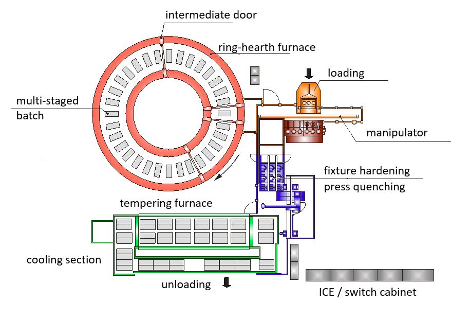
Figure 1. Donut-shaped rotary-hearth furnace for carburizing with press quenching Source: AICHELIN HOLDING GmbH
An example is the quenching and tempering of automotive forgings directly from the forging temperature without reheating, which has shown significant potential for energy and CO2 savings. Although the reduced toughness or measured impact energy of quenching and tempering from the forging temperature may be a drawback due to the coarser austenite grain size, this can be partially improved by Nb micro-alloyed steels and higher molybdenum (Mo) contents for more temper-resistant steels; it may also be necessary to use steels with modified alloying concepts when changing the process.1, 2 AFP steels (precipitation-hardening ferritic pearlitic steels) and bainitic air-hardening steels can also be interesting alternatives, since reheating (an energy-intensive intermediate step) is no longer necessary.
Similar considerations apply to direct hardening instead of single hardening in combination with carburizing processes because of the elimination of re-austenitizing. Distortion-sensitive parts often need to be quenched in fixtures due to the dimensional and shape changes caused by heat treatment. Heat treated parts are often carburized in multipurpose chamber furnaces or small continuous furnaces, cooled under inert gas, reheated in a rotary-hearth furnace, and quenched in a hardening press. In contrast, ring-shaped (aka donut-shaped) rotary-hearth furnaces allow carburizing and subsequent direct quenching in the quench press in a single treatment step. Figure 1 shows a typical ring-shaped rotary-hearth furnace concept for heat treating 500,000 gears per year/core hardness depth (CHD) group 1 mm.
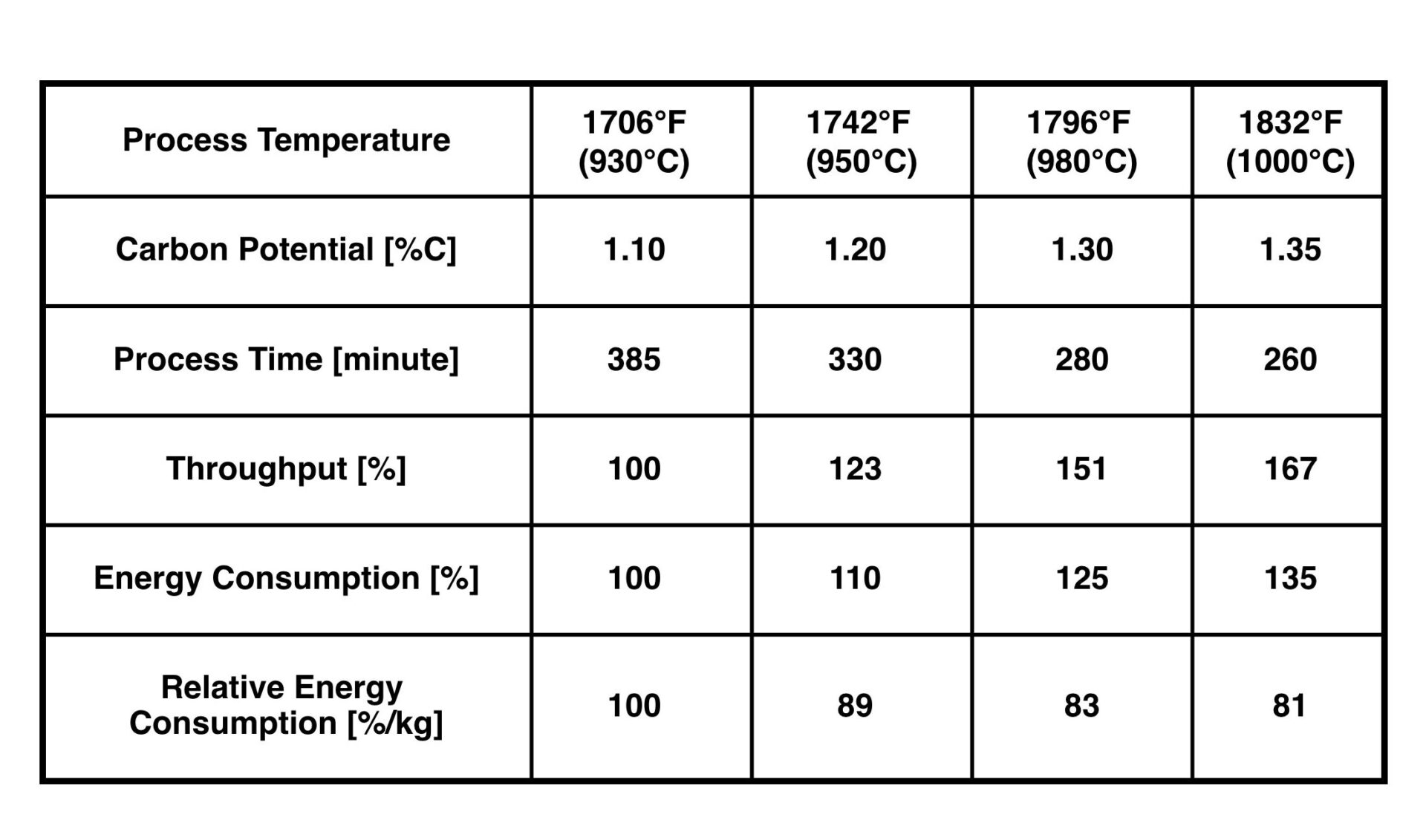
Table 1. Saving potential due to increased process temperature for gas carburizing (pusher type furnace, 20MnCr5, CHD-group 1 mm) Source: AICHELIN HOLDING GmbH
This ring-shaped rotary-hearth concept can save up to 25% of CO2 emissions, compared to an integral quench furnace line (consisting of four single-chamber furnaces, one rotary hearth furnace with quench press and two tempering furnaces as well as two Endothermic gas generators). Due to the reduced total process time (without reheating) and the optimized manpower, the total heat treatment costs can be reduced by 20–25%.
The high-temperature carburizing aspect should also be mentioned, although the term “high-temperature carburizing” is not fully accepted nor defined by international standards. As the temperature increases, the diffusion rate increases and the process time decreases. As shown in Table 1, the additional energy consumption is less than the increase in throughput that can be achieved. Therefore, the relative energy consumption per kg of material to be heat treated decreases as the process temperature increases.
There are three key issues to consider when running a high-temperature carburizing process:
Steel grade: Fine-grain stabilized steels are required for direct hardening at temperatures of 1832°F (1000°C). Microalloying of Nb, Ti, and N as well as a favorable microstructure of the steels reduce the growth of austenite grains and allow carburizing temperatures up to 1922°F (1050°C) for several hours.
Furnace design: In addition to the general aspects of the optimized furnace technology (e.g. heating capacity, insulation materials, and feedthroughs), failure-critical components must be considered separately in terms of wear and tear, whereby condition monitoring tools can support maintenance in this area.
Distortion: This is always a concern, especially in the case of upright loading of thin-walled gear sections. As such, numerical simulations and/or experimental testing should be performed at the beginning to estimate possible changes in distortion and to take measures if necessary.
Figure 2. Recuperative burner with SCR system for NOx reduction
Source: AICHELIN HOLDING GmbH
Heating System
Based on an energy balance that considers total energy losses, and preferably also temperature levels, it can be seen that the heating system plays a significant role. In addition to the obvious flue gas loss in the case of a gas-fired thermal processing furnace, the actual carbon footprint must be critically examined.
In the case of natural gas, the upstream process chain is often neglected in terms of CO2 emissions, but the differences in gas processing (which are directly linked to the reservoirs) and in gas transportation can be a significant factor.3 However, the analysis of energy resources in the case of electric heating systems is much more important. This results in specific CO2 emissions between 30–60 gCO2/kWh (renewable-based electricity mix) and 500–700 gCO2/kWh (coal-based electricity mix). Therefore, a general comparison between natural gas heating and electric heating systems in terms of carbon footprint is often misleading.
Figure 3. Comparison of specific CO2 emissions
Source: AICHELIN HOLDING GmbH
Nevertheless, in the case of gas heating, the aspect of combustion air preheating should be emphasized, as it has a significant influence on combustion efficiency. The technical possibilities in this area are well known and include both systems with central air preheating and decentralized concepts, where the individual burner and the heat exchanger form a single unit. Recuperator burners are often used in combination with radiant heating tubes (indirect heating) in the field of thermochemical heat treatment. With respect to oxy-fuel burners, it should also be noted that the formation of thermal NOx increases with increasing combustion temperature and temperature peaks. To avoid exceeding NOx emissions, staged combustion and so-called “flameless combustion” — characterized by special internal recirculation — and selective catalytic reduction (SCR) can be used. The latter secondary measure, together with selective non-catalytic reduction (SNCR), has been state-of-the-art in power plant design for decades and has become widely known because of its use in the automotive sector. This system can also be adapted to single burners (Figure 2). In this way, NOx emissions can be reduced to 30 mg/Nm3 (5% reference oxygen), depending on the injection of aqueous urea solution, as long as the exhaust gas temperature is in the range of 392/482°F (200/250°C) to 752/842°F (400/450°C).4
Whether electric heating is a viable alternative depends on both the local electricity mix and the design of the heat treatment plant, which may limit the space available for the required heating capacity. In addition to these technical aspects, the security of supply and the energy cost trends must also be considered. Both of these factors are significantly influenced by the political environment. Figure 3 shows an example of the specific carbon footprint per kg of heat treated material with the significant losses based on the example of an integral quench furnace concept in the double-chamber and single-chamber variants electrically heated (E) and gas heated (G). The electric heating is based on a fossil fuel mix of 485 gCO2/kWh. Once again, it is clear that a general statement regarding CO2 emissions is not possible; rather, the boundary conditions must be critically examined.
Waste Heat Recovery — Strengths and Weaknesses of the System
Although improvements in the energy efficiency of heat treatment processes, equipment designs, and components are the basis for rational energy use, from an environmental perspective it is important to consider the total carbon footprint. An energy flow analysis of the heat treatment plant, including all auxiliary equipment, shows the total energy consumption and thus the potential savings. Quite often the temperature levels and time dependencies involved preclude direct heat recovery within the furnace system at an economically justifiable investment cost. In this case, cross-plant solutions should be sought, which require interdepartmental action but offer bigger potential.
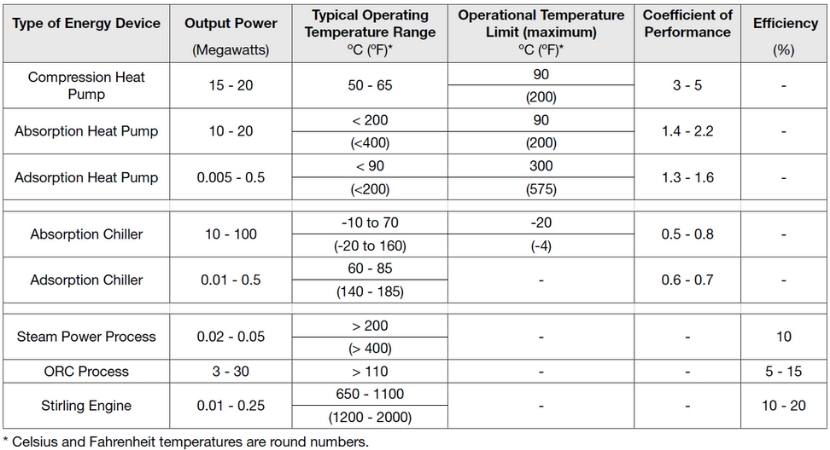
In addition to the classic methods of direct waste heat utilization using heat exchangers, also in combination with heat accumulators, indirect heat utilization can lower or raise the temperature level of the waste heat by using additional energy (chiller or heat pump) or convert the waste heat into electricity. The overview in Table 2 provides reference values in terms of performance class and temperature level for the alternative technologies listed.
Process Gas for Case Hardening
Case hardening — a thermochemical process consisting of carburizing and subsequent hardening — gives workpieces different microstructures across the cross-section, the key factor being high hardness/strength in the edge region. A distinction can be made between low pressure carburizing in vacuum systems and atmospheric carburizing at normal pressure. Both processes have different advantages and disadvantages, with atmospheric heat treatment being the dominant process.
Table 2. Overview of alternative waste heat applications5, 6 Source: AICHELIN HOLDING GmbH
In terms of carbon footprint, atmospheric heat treatment has a weakness due to process gas consumption. To counteract this, the following aspects have to be considered: thermal utilization of the process gas — indirectly by means of heat exchangers or directly by lean gas combustion (downcycling); reprocessing of the process gas (recycling); reduction of the process gas consumption by optimized process control; and use of CO2-neutral media (avoidance). This article focuses on avoidance by optimizing process gas consumption and using of CO2-neutral media.
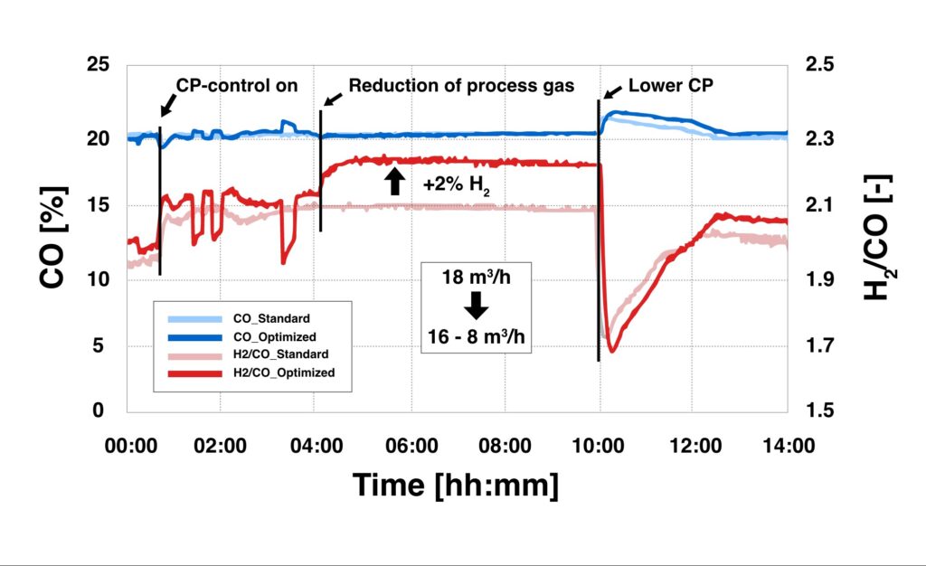
Typically, heat treatment operations are still run with constant process gas quantities based on the most unfavorable conditions. Based on the studies of Wyss, however, process control systems offer the possibility to adapt the actual process gas savings to the actual demand.7 In a study of an industrial chamber furnace, a 40% process gas savings was demonstrated for a selected carburizing process. In this heat treatment process with a case hardness depth of 2 mm, the previously used constant gas flow rate of 18 m3/h was reduced to 16 m3/h for the first process phase and further reduced to 8 m3/h after 3 hours. Figure 4 shows the analysis of the gas atmosphere, where an increase in the H2 concentration could be detected due to the reduction of the gas quantities. With respect to the heat treatment result, no significant difference in the carburizing result was observed despite this significant reduction in process gas volume (and the associated reduction in CO2 emissions). The differences in the carbon profiles are within the expected measurement uncertainty.
Figure 4. CO and H2/CO concentration at various process gas volumes
Source: AICHELIN HOLDING GmbH
The carbon footprint of the process gas, however, must be fundamentally questioned. In the field of atmospheric gas carburizing, process gases based on Endothermic gas (which is produced by the catalytic reaction of natural gas or propane with air at 1832–1922°F/1000–1050°C) and nitrogen/methanol and methanol only systems have established themselves on a large scale. Methanol production is still mostly based on fossil fuels (natural gas or coal), the latter being used mainly in China. Although alternative CO2-neutral processes for partial substitution of natural gas — keywords being “power to gas” (P2G) or “synthetic natural gas” (SNG) — have already been successfully demonstrated in pilot plants, there are no signs of industrial penetration. Nevertheless, there is a definite industrial scale in the area of bio-methanol synthesis, though so far, purely economic considerations speak against it, as CO2 emissions are still not taken into account.
The question of the use of bio-methanol in atmospheric gas carburizing has been investigated in tests on an integral quench furnace system. A standard load of component parts with a CHD of 0.4 mm was used as a reference. Subsequently, the heat treatment process was repeated with identical process parameters using bio-methanol instead of the usual methanol based on fossil fuels. Both the laboratory analyses of the methanol samples and the measurements of the process gas atmosphere during the heat treatment process, as well as the evaluation of the sample parts with regard to the carbon profile during the carburizing process, showed no significant difference between the different types of methanol. Although this does not represent long-term experience, these results underscore the fundamental possibility of media substitution and the use of CO2-neutral methanol.
Conclusion
Facing the challenges of global warming — intensified by the economic pressure of rising energy costs — this article demonstrates the energy-saving potential in the field of heat treatment. In addition to already established solutions, the possibilities of the smart factory concept must also be integrated in this industrial sector. Thus, heat treatment comes a significant step closer to the goal of a CO2-neutral process in terms of Scopes 1, 2, and 3 regarding emissions under the given boundary conditions.
References
[1] Karl-Wilhelm Wegner, “Werkstoffentwicklung für Schmiedeteile im Automobilbau,” ATZ Automobiltechnische Zeitschrift 100, (1998): 918–927, https://doi.org/10.1007/BF03223434. [2] Wolfgang Bleck and Elvira Moeller, Steel Handbook (Carl Hanser Verlag GmbH & Co. KG, 2018). [3] Wolfgang Köppel, Charlotte Degünther, and Jakob Wachsmuth, “Assessment of upstream emissions from natural gas production in Germany,” Federal Environment Agency (January 2018): https://www.umweltbundesamt.de/publikationen/bewertung-der-vorkettenemissionen-beider. [4] Klaus Buchner and Johanes Uhlig, “Discussion on Energy Saving and Emission Reduction Technology of Heat Treatment Equipment,” Berg Huettenmaenn Monatsh 168 (2021): 109–113, https://doi.org/10.1007/s00501-023-01328-5. [5] Technologie der Abwärmenutzung. Sächsische Energieagentur – SAENA GmbH, 2. Auflage, 2016. [6] Brandstätter, R.: Industrielle Abwärmenutzung. Amt der OÖ Landesregierung, 1. Auflage, 109–113, https://doi.org/10.1007/s00501 02301328-5. [7] U. Wyss, “Verbrauch an Trägergas bei der Gasaufkohlung,” HTM Journal of Heat Treatment Materials 38, no. 1 (1983): 4-9, https://doi.org/10.1515/htm-1983-380102.
About the Author
Dr. Klaus Buchner
Head of Research and Development
AICHELIN HOLDING GmbH
Klaus Buchner holds a doctorate and is the head of research and development at AICHELIN HOLDING GmbH. This article is based on Klaus Buchner’s article, “Reduktion des CO2-Fußabdrucks in der Wärmebehandlung” in Prozesswärme 01-2023 (pp. 42-45).
For more information: Klaus at klaus.buchner@aichelin.com.
This article content is used with the permission of heat processing, which published this article in 2023.
Find Heat Treating Products And Services When You Search On Heat Treat Buyers Guide.Com
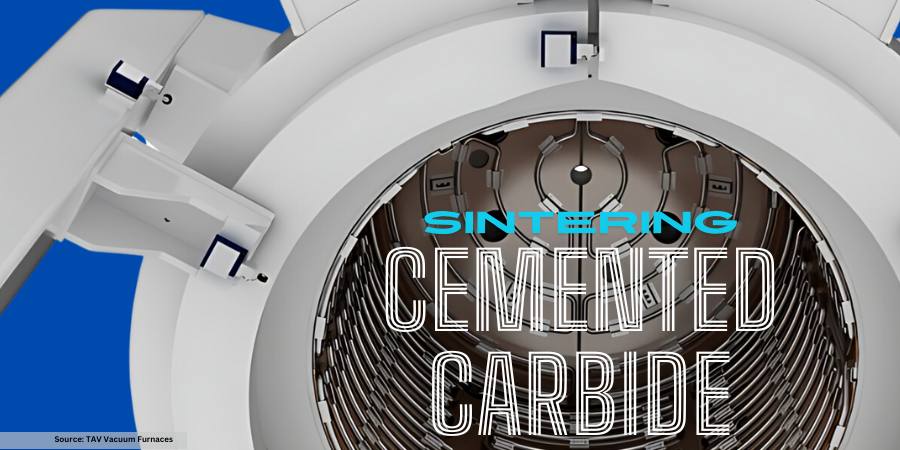
When processing cemented carbide, there are a few considerations you need to understand to use the proper sintering equipment. One of the biggest factors is the actual material; what is the colbalt content level of the processed material?
In this best of the web article, walk through the steps of dewaxing, sintering for appropriate densification, and the processing temperatures that are required for sintering cemented carbide.
An Excerpt:
“Other than mechanical stresses due to the differential pressure between inside and ambient pressure outside the furnace, operating at relatively high temperatures with high pressure of gas would lead to significant dissipations of heat to the external environment. This is not only anti-economic from an efficiency point of view, but could also compromise the structural integrity of the water-cooled steel vessel of the furnace by overheating it.”
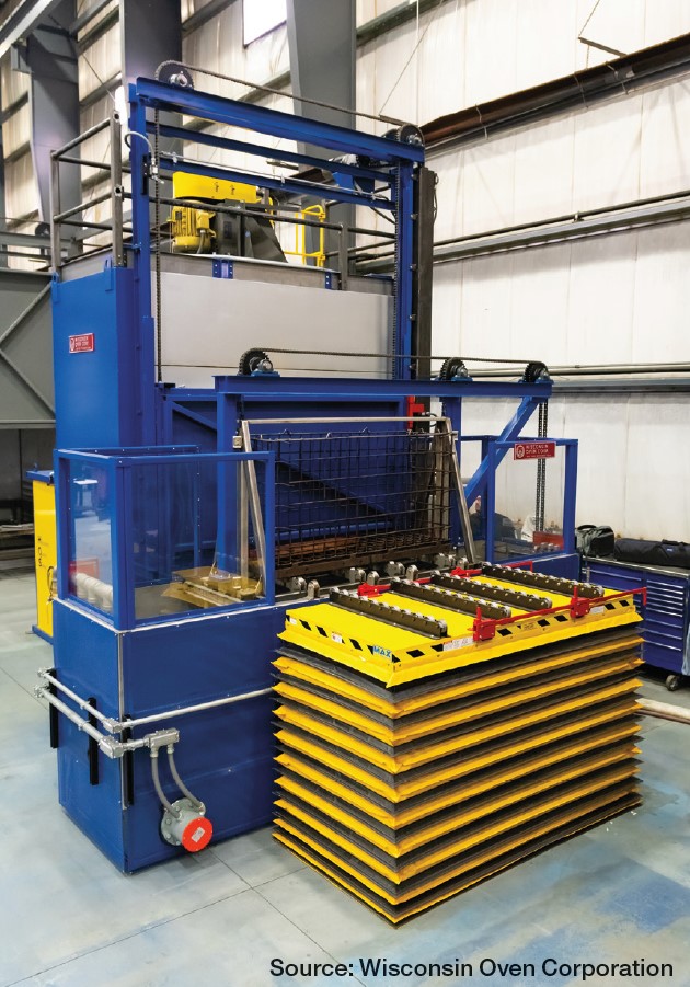
Precise heat treating is essential to enable components to withstand space exploration. In this Technical Tuesday, Mike Grande, vice president of Sales at Wisconsin Oven Corporation, discusses the role of aluminum solution treatment and aluminum aging in heat treating space exploration components.
This column was first released in Heat Treat Today March 2024 Aerospace Heat Treatprint edition.
Contact us with your Reader Feedback!
In space exploration, the various parts, electronic components, and materials used to make the rockets, crew capsules, rovers, and other equipment, are subjected to brutal extremes of temperature, vacuum, and radiation. In order to withstand these extreme environments without failure, the parts must be manufactured to very tight tolerances and precisely heat treated. Therefore, convection heat treatment emerges as a critical process in the manufacturing of space exploration components and materials, offering tight control over temperature profiles and the microstructure of materials.
Heat treatment involves heating a material to a specific temperature, holding it at that temperature for a certain duration, and then cooling it down at a controlled rate, which can be rapid or gradual, depending on the objective. The purpose of heat treatment is to improve the material’s mechanical properties, such as strength, ductility, and toughness. Probably the most common metal used in space exploration is aluminum. It is an excellent choice for spacecraft components because it is lightweight, durable, and has excellent thermal conductivity, which is necessary for components that need to dissipate heat.
The first stage of the Falcon 9, for example, utilizes four legs used during landing. They are manufactured from an extremely light, rigid, aluminum honeycomb material that also contains carbon fiber and has a very high strength to weight ratio. Another aluminum component common in space exploration is gas transfer tubes, used to transfer gases, such as methane, between chambers in the interior of rocket propulsion systems. Additionally, there are composite overwrapped pressure vessels (COPVs), which carry compressed fuels such as hydrogen and oxygen, among other gases. These are made of an aluminum tank covered with filament-wound, resin-impregnated composite material, which forms an extremely robust structure capable of withstanding the high pressures created by compressed gases and the rigors of high-speed propulsion. For aluminum to be useful in space applications, it must be heat treated to give it the strength and durability required.
Aluminum Solution Treatment
Since aluminum has such widespread use in space exploration, aluminum heat treatment plays a central role in this industry, with solution treatment and aging being the most common heat treatments utilized. All aluminum materials that require high strength are solution heat treated, then subsequently aged, in two separate heat treat processes. The purpose of solution heat treatment is to evenly dissolve the alloys contained in the aluminum, such as manganese, magnesium, copper, zinc, and silicon, and then rapidly quench it to retain the grain structure. The aluminum alloy is heated and held at a temperature of 800°F to 1000°F (420°C to 540°C), which is just below its melting point. The aluminum is then quenched in water or a water/glycol mixture quickly (within 7 to 15 seconds) to essentially “freeze” the microstructure before the alloying elements can redistribute themselves.
Aluminum Aging
After quenching, aluminum is precipitation hardened. Also known as artificial aging, this process involves heating the aluminum at a lower temperature, typically in the range of 200°F to 400°F (93°C to 204°C) for several hours. This final process dramatically increases the hardness, yield strength, and ultimate strength of the aluminum, making it suitable for use in space applications.
A solution treatment system for processing aluminum
The above is just a sample of the many types of heat treatments for materials used in space exploration. Other examples are annealing, tempering, normalizing, and hydrogen embrittlement relief, to name a few. In conclusion, heat treatment plays a critical role in the manufacturing of parts used in space exploration and is essential to the reliability and safety of space missions.
About the Author
Mike Grande,
Vice President
of Sales,
Wisconsin Oven
Corporation
Mike Grande has a 30+ year background in the heat processing industry, including ovens, furnaces, and infrared equipment. He has a BS in mechanical engineering from University of Wisconsin-Milwaukee and received his certification as an Energy Manager (CEM) from the Association of Energy Engineers in 2009. Mike is the vice president of Sales at Wisconsin Oven Corporation.
For more information: Contact sales@wisoven.com.
Find Heat Treating Products And Services When You Search On Heat Treat Buyers Guide.Com
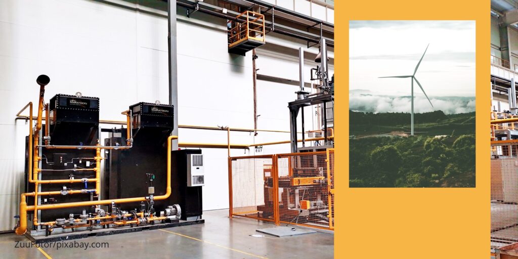
NGC Gears, a manufacturer of wind power gearboxes, has completed the installation of two additional Endothermic generators from a manufacturer with North American locations.
UPC-Marathon, a Nitrex company, installed the Endo generators at NGC Gears‘ its new facility in Jinhu, China. This acquisition brings the total of generator sets to five since 2022, collectively generating an impressive 800 m³/h (22,252 ft3/h) capacity of Endothermic gas supplied to carburizing and hardening furnaces used for processing various gear components. The latest installations in February and March of 2024 support the heat treating operations of the company’s wind energy gearbox production.
NGC’s decision to expand capacity is in response to the growing demand for wind power solutions in China and globally. The new Endothermic gas generating systems will significantly enhance the company’s production capabilities, enabling NGC to meet increasing market needs with greater efficiency and reliability.
EndoFlex generators from UPC-Marathon (Source: Nitrex)
EndoFlex offers precise control of production media to the carburizing and hardening environments, leading to higher quality gear production with improved longevity and performance. The result is improved carburizing and hardening processes, higher-quality hardened gears, reduced operating costs, and increased efficiency, as well as immediate cost savings through reduced electricity and gas consumption and minimized waste.
Johnny Xu, general manager at UPC-Marathon China, shared, “The latest EndoFlex investments align with NGC’s development of low-consumption, high-efficiency gearbox products for large-scale onshore and offshore wind turbines.”
This press release is available in its original form here.
EcoTitanium, a European plant for recycling and refining titanium alloys for critical applications, was opened in France in 2017. It was the first plant in Europe to melt titanium with a cold hearth furnace – a technology that allows users to recycle titanium reverts coming from forging and machining castings from the aerospace supply chain.
The SECO/WARWICK Group was chosen as the main supplier of advanced vacuum metallurgy technology for this strategic European project, securing the creation of an autonomous European titanium channel.
Sławomir Tomaszewski, director of the Vacuum Melting Furnaces Team in the SECO/WARWICK Group, comments, “The innovative VAR furnace will increase the Partner’s production capacity and can respond to the increased demand for titanium in Europe. EcoTitanium has created the first integrated titanium processing plants in Europe, which opens the door to European, ecological, and innovative solutions for the aerospace industry. We are glad that our Group is part of this strategic project and that Retech and SECO/WARWICK brand solutions constitute the core of the machine park.”
Earl Good Managing Director Retech Systems, LLC Source: Retech
“For EcoTitanium, we, as Retech and SECO/WARWICK, delivered two furnaces seven years ago: a plasma furnace (PAM) for consolidation and refining of titanium scrap using plasma torches operating in an inert gas atmosphere, and a VAR arc furnace for further refining of titanium ingots obtained from the PAM furnace. The current contract is a continuation of this project. We will deliver a second VAR furnace, which will significantly increase the Partner’s processing capabilities,” said Earl Good, managing director of Retech.
The new furnace’s advantage is its perfect fit into the customer’s existing infrastructure. For safe operation, VAR furnaces require complex construction work: a bunker, an explosive tunnel, as well as a dedicated control room located outside the furnace operating area.
This system is unique because current solutions in the field of furnace safety will be implemented at the design stage. These solutions result from both the experience gained by EcoTitanium and the SECO/WARWICK Group’s experience.
Source: SECO/WARWICK
“The delivery of this new VAR furnace will help us to secure our customer’s growing needs for producing titanium in the context of unprecedented production ramp-ups. We are pleased to open this new chapter of EcoTitanium’s history with our long-term partner SECO/WARWICK. SECO/WARWICK has indeed offered us best-in-class solutions in the field of vacuum metallurgy technology, in particular with its PAM systems from its Retech brand, which allows us to use around 75% of recycled materials and to divide by up to four the CO2 emissions created by titanium melting,” says Jean-François Juéry, president of EcoTitanium.
Titanium, a transition metal with unique properties, is valued for its strength-to-weight ratio. It has comparable durability to steel but is 50% lighter, making it an attractive choice for industries looking for strength without additional weight. The aerospace industry consumes over 30% of global demand, and the chemical sector another 40%. Additionally, titanium has found use in medicine, especially in joint replacement procedures, dental implants, and electronics.
This press release is available in its original form here.
The amazing materials that are produced through additive manufacturing (AM) and 3D machining often require post-processing heat treatments before these become final components that launch into space. What are the trends of AM/3D outside our planet, and what technical resources are available to you as you make one step into this field? This original content piece from the Heat Treat Today editors will help you understand where technology stands in 2024.
Why Does AM/3D Go to Space?
Contact us with your Reader Feedback!
A broad spectrum of industries have found the appeal of additively manufactured parts, industries ranging from mining to medical and automotive to space. Much of this has to do with complexity of components that new engineering techniques require, the desire to save on material costs, and the ability to condense lead time. For some, additive manufacturing is becoming essential to the space industry; as Tobias Brune, head of the Business Unit Additive Manufacturing at TRUMPF, has commented, “With our 3D printing technology, we are driving the commercialization of the space-travel industry. If you want to be successful in the space-travel industry today, you have to use additive manufacturing.”
When should you expect this transition? Now.
In January of this year (2024), the first metal 3D printer for space was launched to the Columbus module of the International Space Station (ISS). This is a very active, integrated sense of seeing AM in the aerospace industry, and test runs with this equipment will ensue.
Flight model of 3D Metal Printer Launched on NG-20 Source: ESA
The Exploration Company in Europe plans to use 3D printers from TRUMPF (laser specialist) to print core components in engines for spacecrafts. The intent: missions in Earth’s orbit and to the moon.
Heat Treat & thermal Processing Requirements of Post-ProcessingAM
If you are going to get involved in AM, it is essential to have the right equipment. One of the most talked about equipment is hot isostatic pressing (HIP) technology. Often, heat treat operations use HIP equipment for post-process heat treating in order to get the solid part they desire. For the most part, commercial heat treaters have positioned themselves to handle the R&D required to navigate the terrain of overcoming processing challenges of new/complex parts and creating standardizations. However, privateR&D facilities and departments are also building out their capabilities to handle AM in HIP.
However, so also have vacuum furnaces been a key leader in heat treating AM components. Here, commercial heat treaters have also made moves to expand their equipment/process offerings to accommodate AM parts.
So also do atmosphere considerations need to be considered, withgasses like H2 competing trying to capture the limelight.
Continue the Exploration: AM/3D Articles for Space
Looking for an introduction to the AM/3D topic for heat treaters? Begin with this article by Animesh Bose, an engineering pioneer: “The Role Of Heat Treat in Binder Jetting AM for Metals.” The article uncovers the history of one of the most important types of AM/3D manufacturing — binder jetting AM.
Then, take a step over for an industry focus on what “heat treatments for space” look like. Mike Grande eloquently summarized the current processes needed in space in this editorial from the March 2024 Aerospace print edition. Read “The Role of Heat Treatment in Space Exploration” in the digital edition of the magazine.
In-house or commercial? This article presents critical considerations of space components — with a particular emphasis on the importance of AM/3D — when considering how to grow your processing expertise and capabilities. Several examples from the frontlines of R&D are presented by Noel Brady in his article. Read the editorial, “Thermal Processing for Space and Additive Manufacturing,” for excellent illustrations.
Finally, hone in on the topic with a case study about developments in HIP technology for space component post-processing. This article begins with context confronting issues of structural integrity, especially of complex space components, with HIP. Andrew Cassese gets to the case study towards the end of his article, “High Pressure Prepares Parts for Space.”
Find Heat Treating Products And Services When You Search On Heat Treat Buyers Guide.Com
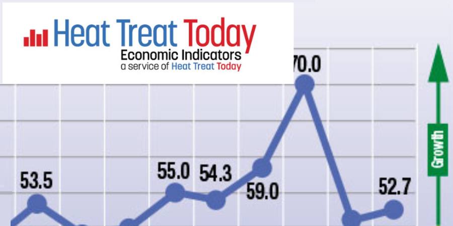
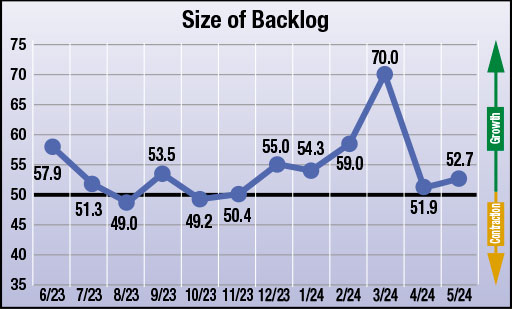
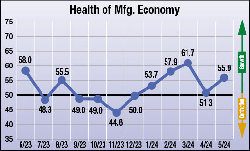
The four heat treat industry-specific economic indicators, gathered by Heat Treat Today each month since June 2023, indicate expectations for economic growth in May compared to what suppliers experienced in April. However, while growth is still expected, it appears that most suppliers are more tame in their projections for growth across most indicators.
The numbers, which were compiled in the second week of May, show that responding parties strongly anticipate all four indices — number of inquiries, value of bookings, size of backlogs, and health of manufacturing economy — to grow. Again this is growth as is compares to the previous month (April). One specific indicator does stand out, though: Manufacturers are expecting significant growth in number of inquiries.
The results from this month’s survey (May) are as follows; numbers above 50 indicate growth, numbers below 50 indicate contraction, and the number 50 indicates no change:
Anticipated change in the Number of Inquiries from April to May: 61.5
Anticipated change in Value of Bookings from April to May:56.8
Anticipated change in Backlog Size from April to May: 52.7
Anticipated change in the Health of the Manufacturing Economy from April to May: 55.9
Data for May 2024
The four index numbers are reported monthly by Heat Treat Today and made available on the website.
Heat TreatToday’sEconomic Indicatorsmeasure and report on four, heat treat industry indices. Each month, approximately 800 individuals who classify themselves as suppliers to the North American heat treat industry receive the survey. Above are the results. Data started being collected in June 2023. If you would like to participate in the monthly survey, please click here to subscribe.
Find heat treating products and services when you search on Heat Treat Buyers Guide.com