Planning 2022 heat treat goals would be lacking without considering at least one of the major heat treat shows in North America. In Heat Treat Today's Medical & Energy December 2021 print edition, the Metal Treating Institute highlights the biannual Furnaces North America show that happens in quarter three. Read about the three main reasons to attend in the article below!
Image 1
Furnaces North America 2022(FNA 2022), presented by the Metal Treating Institute, in partnership with its media partner, Heat Treat Today, is the heat treating industry’s marquee event every other year, and will be held October 3–5, 2022 in Indianapolis, IN. FNA 2022 will attract attendees from over 40 states and 20 countries, including attendees from Fortune 500 companies. For three days, attendees take part in networking, connecting, and learning about the vast changes taking place on emerging technologies, industry trends, and advances in equipment.
FNA show producer Tom Morrison said, “The 2020’s will provide unbelievable opportunity, but not without challenges. Change is happening at such a rapid pace in today’s economy, both commercial and captive heat treat plants can’t afford to miss a show like FNA 2022. Demographic shifts, emerging technologies, a shortage of workers, plant automation, and consumer buying habits are driving what is manufactured . . . when . . . and how. At FNA, leaders in heat treating companies can connect with the content and executives that can deliver the solutions and ideas they need to thrive this decade.”
The answers to your most pressing challenges in your heat treat operation can be found at FNA 2022, by attending technical sessions with suppliers you meet, connecting at a booth with another heat treater, or while enjoying one of the social events.
FNA 2022 has three dynamic elements that will deliver the answers you and your team need to maximize your productivity, people resources, and profits.
Image 2
ELEMENT #1:
Learning that LASTS
FNA 2022’s technical conference, designed by a team of heat treaters and suppliers, has 35 key sessions that focus on a wide array of technical issues including:
Industry 4.0 and Automation
Productivity and Data
Processes
Equipment
Standards and Pyrometry
Controls and Materials
Maintenance
Emerging Technologies
FNC/Nitriding
Quenching and Cooling
ELEMENT #2:
Image 3
Business that CONNECTS
The most active part of any FNA experience is the trade show. With over 170 top suppliers in every facet of heat treating, this is where the daily needs of heat treaters are fulfilled. On the show floor, heat treaters and suppliers connect to learn about each other, challenges heat treaters are facing, and how suppliers can solve those issues. FNA’s expo is a must for any owner, GM, plant manager, or manager in maintenance, quality, or production. FNA 2022 encourages companies to bring key management team members to help introduce them personally to the new trends and technologies shaping the future of heat treating.
ELEMENT #3:
Networking is KING
At FNA, attendees experience a set of exciting social functions that allow heat treaters and suppliers alike to connect with one another to discuss the new ideas they learn during the conference and trade show. They also share their daily experiences in dealing with issues like energy, employee recruitment/retention, maintenance, audit compliance, plant safety, and equipment purchases. FNA social events also help suppliers to take a break from the trade show booth and listen to the heat treater’s needs in a more informal environment. This provides suppliers an opportunity to serve the heat treater better and develop products for their specific needs.
Image 4
Furnaces North America 2022 provides the networking, technical training, and business connection that heat treaters need to build a bright future within their operation. Mark your calendar now and take the opportunity to attend FNA 2022 in Indianapolis, IN, October 3–5, 2022.
Today, we cast our sights overseas to our European information partner, heatprocessing, to find out what’s new internationally. Major movements in steel and implementations of new furnace tech are the themes.
Steel Wire Plant Needs New Bell Annealer System
“After detailed technological analysis, Italy’s Trafilerie San Paolo, srl. has selected a Hicon/N2 bell annealer facility for steel wire by Ebner Industrieofenbau.
“The facility will be installed in TSP’s newly-remodeled steel wire plant in Molteno (LC). Initial installation will comprise two Hicon/N2 workbases, one heating bell and one cooling bell, as well as all required peripheral equipment. The scope of supply includes all required supplementary equipment such as hydraulic power supply equipment, a pressure control station, analysing systems, state-of-the-art electrical systems with automation technology and a central visualisation system terminal.”
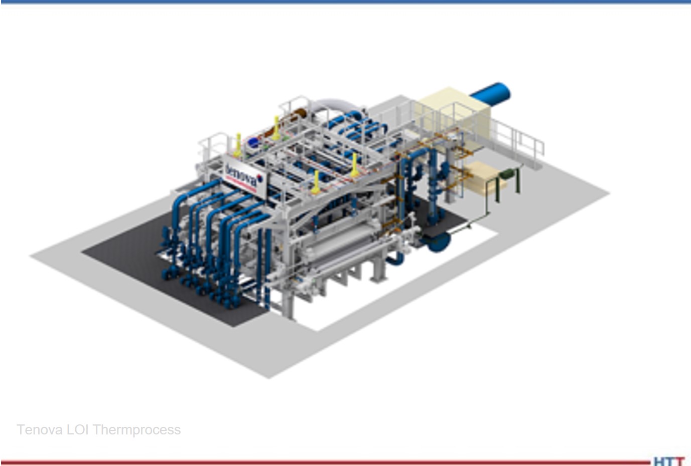
“Wuhan Iron & Steel Co. Ltd. (WISCO) has awarded Tenova LOI Thermprocess another order for the installation of a continuous quench for efficient cooling of thin steel plates.
“The quench is specially designed for efficient cooling of thin and very thin plates of high strength and wear resistant material. The quenches adopted for this application ensure maximum hardness and outstanding flatness combined with unique and powerful models and overall automation.”
Peter Zawistowski Managing Director SECO/VACUUM TECHNOLOGIES, USA Source: secowarwick.com
An international extrusion die maker with in-house heat treating is set to modernize its gas-fired combustion technology with eleven furnaces at three U.S., Canada, and Mexico locations. The upgrade: new vacuum, nitriding, and tempering furnaces that will increase consistency and precision nitriding potential and reduce gas emissions.
SECO/VACUUMwill deliver four Vector®single-chamber gas quench vacuum furnaces, six tempering furnaces, and one ZeroFlow® pit-type gas nitriding furnace for use in the aluminum extrusion industry.
"This is a big deal for the customer," said Peter Zawistowski, managing director of SECO/VACUUM. "They’ll benefit from a complete modernization of their heat treatment capabilities across all of North America with clean, efficient vacuum heat treatment technologies. It’s a bigger deal for vacuum heat treating as a whole. It proves we’ve made great strides in the industry to convert legacy atmosphere users into vacuum technology believers."
Derek Dennis President Solar Atmospheres of California
To support R&D and additive manufacturing projects, Solar Atmospheres of California (SCA) has added some small vacuum furnace capacity to their equipment offerings.
The new vacuum furnace was acquired from SCA’s furnace manufacturing sister facility, Solar Manufacturing (SAMI) located in Sellersville, PA, and was specifically designed to process a variety of materials between 600°F – 2400°F (+/-10°F) in both vacuum and/or partial pressure environments. Precise cooling capability up to 2-Bar in argon, nitrogen or helium is available with a maximum operating temperature up to 2650°F. The furnace is also equipped with the SAMI’s state-of-the-art SolarVac® Polaris Control System for optimum performance and precise cycle control.
"We are pleased to add this needed piece of vacuum furnace equipment to service our valuable customers," said Derek Dennis, president of SCA. "The additive manufacturing industry continues to grow, and this new furnace will allow SCA to respond to small builds and R&D projects quickly and precisely."
A Midwest manufacturer of brass components is upgrading their heat treat capabilities with a new furnace. The 24″ wide, 3 zone mesh belt annealing furnace will provide improved energy efficiency, reduced atmosphere consumption, and consistent and reliable part quality, as compared to an older design.
The brass annealing furnace from Gasbarre Thermal Processing Systems is designed with a maximum operating temperature of 1650℉ with a capacity of 800 lbs/hr, and utilizes a blend of nitrogen and hydrogen atmospheres. The system incorporates an Allen-Bradley PLC and HMI with automated atmosphere and water temperature control and datalogging.
Precise temperature regulation is undoubtedly the top variable in the industrial process that influences the quality of the final product. Using intelligent power control and predictive maintenance, silicon controlled rectifiers (SCRs) play a major role in temperature regulation and in improving the industrial heat treating process. What are SCRs and how do they improve the industrial heat treat process?
In this Technical Tuesday feature, written by Tony Busch, sales application engineer at Control Concepts, Inc. and Meredith Barrett, manager of Marketing and Business Development at Weiss Industrial, discover how SCRs can help you improve temperature regulation.
(This article was originally published in Heat Treat Today’s November 2021 Vacuum Furnaceprint edition.)
Introduction
Meredith Barrett Marketing and Business Development Manager, Weiss Industrial
Tony Busch Sales Application Engineer Control Concepts, Inc.
In manufacturing metals and in the heat treat industry, temperature regulation is crucial. SCR power controllers regulate the flow of electricity from the grid to a major heating element in a manufacturing process. Usually, the major heating element is a furnace, kiln, or oven, and the SCR is often connected to the heating element directly or to a transformer connected to the heating element.
The ability to calculate resistance in a furnace can provide information on the overall condition of an element. The SCR collects data and communicates it back to the network. Predictive maintenance is knowing when an element has reached its useful life. This article will define what an SCR power controller is, how it functions, and the different firing modes.
Digital Thyristor/SCR Power Controller Overview
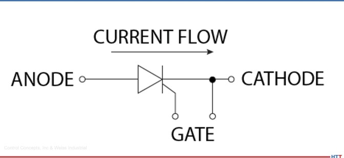
“Thyristor” is a Greek-derived word for “door.” The term is a hybrid of the word thyratron and transistor. As defined by ElectricalTechnology.org, a thyratron is a gas-filled tube that works as an SCR. SCR and thyristor are interchangeable terms in describing a device with four semiconductor layers or three PN junctions with a control mechanism. These small machines are known as latching devices. In the context of electrical engineering, a latch is a type of switch where once it’s on, it will remain on after removing the control signal.
Figure 1. Current flow
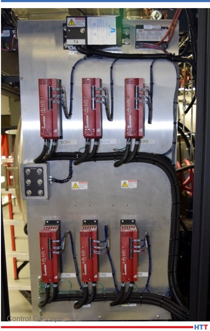
The actual power control module is an advanced electronic device with LED indicators and I/O terminals. The main internal components of an SCR power controller include:
• Semiconductor power devices (SCRs and Diodes)
• Microprocessor-based control circuits normally referred to as the firing circuit
• Heat sink (a means to dissipate the heat generated from semiconductor devices)
• Protective circuits (fuses and transient suppressors)
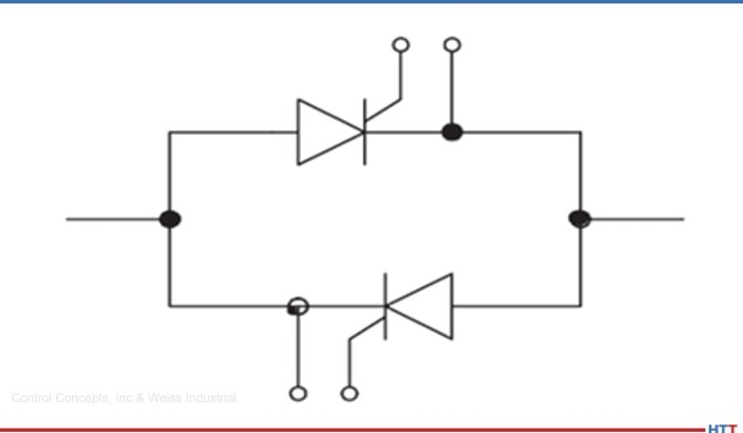
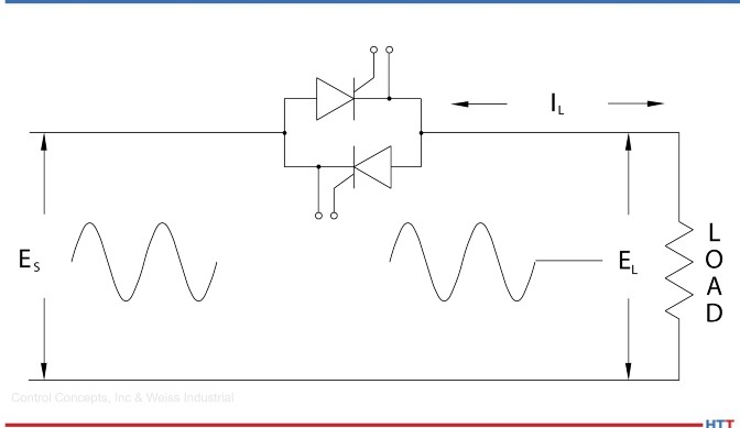
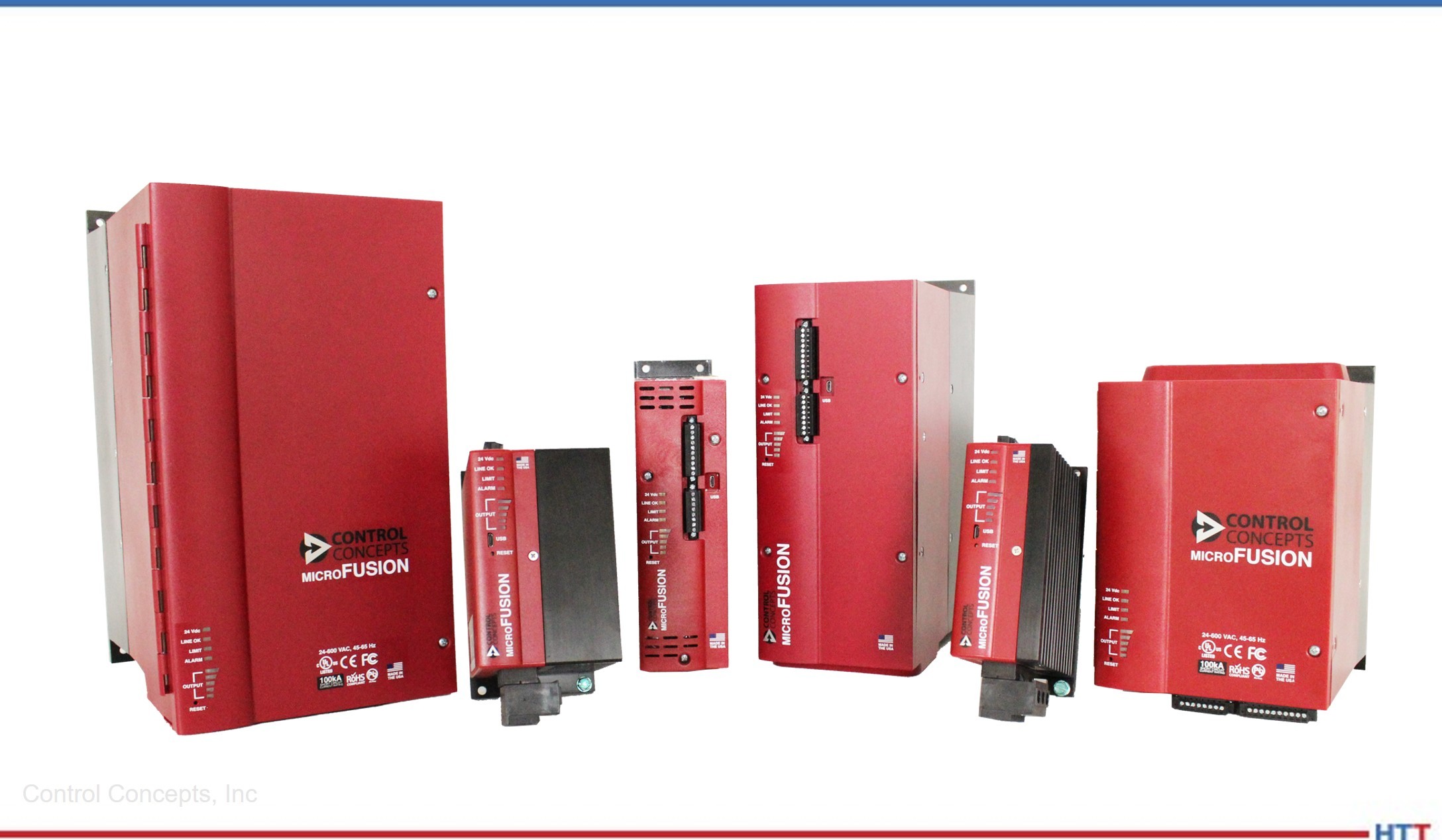
The diagram below is a very basic model showing one leg of an SCR controller. However, in all electrical designs of power controllers, such as the popular Control Concepts MicroFUSION series featured in this article, each controlled leg requires SCRs back-to-back within the power control module because of alternating current.
Figure 2. Basic model of one leg of SCR controller
How are Digital SCR Power Controllers Superior to Their Analog Predecessors?
“Digital” SCR power controllers are basically a concise way of referring to a power controller unit that utilizes a SCR switch (as opposed to a different switching method such as an insulated-gate bipolar transistor (IGBT)) and has all the above components. Additionally, these units contain microprocessors that make them more of a smart device. They are scalable, and easily paired with other digital units, whereas pairing analog power controllers results in potential emitter gain and bias.
Digital SCR power controllers can provide flexibility unmatched by analog units. This flexibility includes various communication options and the ability to switch through fi ring modes with ease, all without requiring the unit to be changed or rewired. The adaptable nature of digital SCR power controllers allows them to be incorporated into an industrial heat treat process much more effortlessly.
Older analog units are not highly configurable like their digital replacements. Newer SCRs not only have configurable faults and alarms, but also savable configuration files which can easily be loaded onto another unit.
Digital SCR power controllers can obtain accuracy and repeatability previously impossible with analog controllers. Digital units have power regulation capabilities that adjust for both variations from the mains voltage and resistance from the heating element. This form of power regulation is not only the most precise way to regulate temperature, but it also allows for process repeatability.
Synchronization of two units connected to the same power source, firing in zero-cross mode, is not ideal. This means that modules should not sync up so that they are on and off in unison. If this should happen, the process would require a large amount of current to be drawn from the source while the controllers are all on, and none when they are off.
The company’s SYNC-GUARD™ feature, not previously available on older SCR controller modules, reduces the peak current draw required from the source over time by causing each controller to attempt to find a time to turn on when fewer, or no other, controllers are firing. However, it has its limitations. The more controllers that are added to application, the probability of them syncing increases. Once ten or more controllers are utilized in an application, it becomes impossible to not have some sync up despite this feature.
Another key difference is that digital SCR power controllers are always calibrated and will never change. This allows the convenience of being able to “set it and forget it.” Newer models have an option of a digital display which was previously unavailable with analog controllers.
How the Latest SCR Power Controllers Improve Industrial Furnace Operations
SCRs can calculate electrical resistance in a furnace and provide precise power control. Intelligent power control has embedded algorithms which teach functions to calculate data and predict what is likely to happen next in the life of a heating element. This capability can determine partial load loss, resistance change, and complete load loss.
Partial load fault detection is a “watchdog” feature that monitors the system for change in resistance. This is useful for detecting an element failure for loads with multiple parallel elements. The feature monitors a user-set tolerance value that determines the drift from the target resistance in the system.
Therefore, an operator can enter the resistance manually or use the innovative “teach function” with a digital SCR controller. This is a form of artificial intelligence that will allow the SCR to learn the heating element through algorithms. The teach function auto-ramps and intelligently saves different resistance values at various setpoints in a process, eliminating guess work.
SCR power controller units attached to industrial furnace
Heater bakeout is an aspect of industrial furnace operations where digital SCRs offer a great amount of control. Industrial furnaces, kilns, and ovens are often lined with some sort of refractory or ceramic material that allows them to withstand extremely high temperatures. Typically, this material can get stressed and crack if heated too quickly, particularly in some submersion heaters where moisture can be present.
Modern SCR power controllers have an actual heater bakeout mode that will increase the temperature to the heating element gradually, allowing the furnace to slowly equalize in temperature. If any moisture is present in the heating element, it is baked away, and either way, slowly ramping up the temperature prevents damage to the refractory. This can prevent both costly furnace repairs and downtime.
Another major advantage of digital SCR controllers is tap change indication that informs the operator when to change voltage taps. Some loads, even if they remain the same, still can influence and change the element resistance over a period of time. Because this affects the power factor, a transformer with multiple voltage taps can be used.
Additionally, digital SCR controllers can also be utilized to achieve a constant output power. The tap change indication feature signals the operator when to adjust the voltage taps to a higher or lower setting on a digital display or digitally via the alarm monitor panel.
Predictive vs. Preventative Maintenance
Predictive maintenance has become a popular buzz word related to “Industry 4.0” as we now enter what is known as the fourth industrial revolution, or digitization of a manufacturing process utilizing an interconnected network of smart devices. The goal of both predictive maintenance and preventative maintenance is to increase the reliability of assets, such as an industrial furnace, oven, or kiln used in the heat treat manufacturing process. This not only avoids costly downtime but increases the life of an asset resulting in substantial savings in maintenance costs.
The main difference between the two is preventative maintenance is simply regularly scheduled upkeep, such as a temperature uniformity survey (TUS) on an industrial furnace. Think, for example, of how you have the oil changed every 3,000 miles in your vehicle because it is common practice for extending the life of your engine: that’s preventative maintenance.
Predictive maintenance is more condition monitoring or intelligence gathering on the health of an asset. It is based on present time and continuous data monitoring from smart devices on an industrial network. Predictive maintenance is knowing when an element needs to be fixed or has reached its useful life and needs to be replaced. Knowing the life of the element allows for a structured shut down preventing expensive unscheduled downtime.
How Do SCRs Achieve Intelligent Power Control?
In the instance of intelligent power control, the SCR acts similarly to a dimmer switch on a lighting fixture. It regulates the amount of electricity going into the furnace, just like the dimmer controls the amount of brightness going into the light bulb. The purpose of regulating the electricity to the heating element is to maintain the desired temperature and prevent damage to the asset from power surges or voltage inrush.
“Resistance” is an electrical engineering term that relates to the amount of current that can flow through a heating element of a furnace, machine, or other electronic device that heats up. Technically, this can be something as simple as your household toaster. When the heating element is cold, the resistance to electricity is lower, allowing more current to pass through. When it is hot, its resistance is higher, blocking the incoming current.
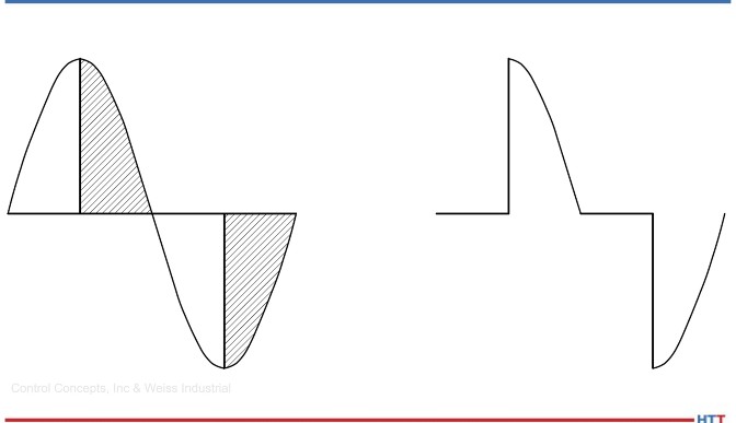
Figure 3. AC supply (left) and load voltage (right)
Both variations in the electricity coming from the grid (the mains voltage) and furnace resistance can cause temperature fluctuations. SCR power controllers accommodate for both variations from the mains voltage and furnace resistance by regulating output current utilizing different firing modes.
Firing Modes of SCRs: Phase-Angle & Zero-Cross Explained
What technically is a “firing mode” when it comes to SCRs? As noted in the SCR diagram, the topology of an SCR includes a control circuit also known as a “firing circuit.” The SCR has feedback and logic to determine how it is going to fire the electric sine wave. Thyristors, as SCRs are more commonly known outside of the U.S., have two basic control modes: phase-angle and zero-cross.
Phase-Angle
When a SCR power controller adjusts the voltage using the firing angle, it is known as phase-angle mode. This is analogous to a dimmer switch on a light fixture. The SCR is acting as a dimmer switch on an industrial furnace. Using phase-angle control, each SCR in a back-to-back pair is turned on for a variable portion of the half-cycle that it conducts. This trims every single half sine wave, giving a very smooth output, hence getting the correct kilowatts to the needed load.
In a heat treat application where the SCR is firing directly into the transformer, phase-angle mode will need to be employed. This protects the transformer from saturation. (See Figure 3.)
Zero-Cross
In zero-cross firing mode, the power controller adjusts the duty cycle to regulate the voltage. Each SCR is turned on or off only when the instantaneous sinusoidal waveform is zero. In zero-cross operation, power is applied for several continuous half-cycles, and then removed for a few half cycles, to achieve the desired load power.
In other words, zero-cross is best described as a blinking on and off. You’re firing a certain amount of full wave cycles, then it is going to turn off for a period of time, and then return to the on mode. An average is taken of the cycles that fire versus do not fire, which gives you control.
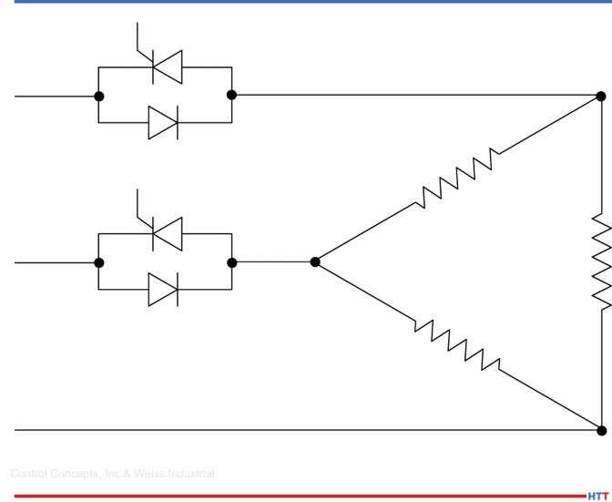
The on and off nature of zero-cross is beneficial for power factor, and the overall cost is lower than running SCRs in phase-angle applications. Simply stated, running SCR power controllers in zero-cross mode versus phase-angle mode consumes less energy and saves money on the electric bill. Zero-cross also produces little to no harmonics. As illustrated below in Figure 4, you can run SCRs in two-phase versus three-phase mode using zero-cross. If the resistance is varying less than 10%, zero-cross can be applied to the heat treat process.
SCR Power Controller Configurations
Single-Phase
In a single-phase configuration, SCRs are running back-to-back to the load, which is looping back up to L1 and L2. This is the most basic SCR set up.
Figure 4. Single-phase configuration
Three-Phase/3-Leg (6SCR)
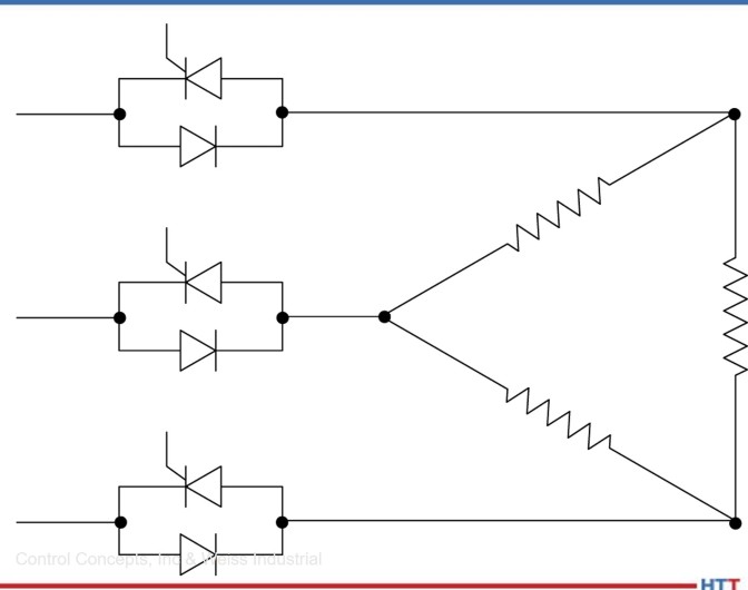
Three-phase is wired in a delta or wye and involves three SCR modules connected in a circuit. This is great for phase-angle control where the SCR is firing into transformers. The topology is beneficial for direct firing as well. Three-phase is effective in high inrush current loads that require a current limit, and it also enables the system to phase without blinking on and off.
Figure 5. Three-phase/3-leg (6SCR) configuration
Three-Phase/2-Leg (4SCR) Zero-Cross Only
This configuration involves two SCR modules controlling two of the legs, and the third leg is connected to the delta or wye but going directly back to supply voltage. This can be more cost effective for an application since it is run in zero-cross mode.
Figure 6. Three-phase/2-leg (4SCR), zero cross mode
Inside Delta
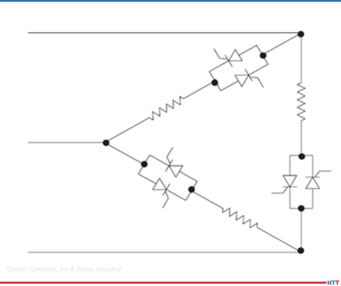
Inside delta configuration is double the wiring. However, it reduces the size of the SCRs needed. Where the SCRs are placed in the circuit in the inside delta configuration will draw less current at the point. This is a more uncommon configuration, and it is found infrequently in the field.
Figure 7. Inside delta configuration
What SCR Is Right For Your Application?
Weiss Industrial, a manufacturer’s representative company, chose to partner with one of the top OEMs to help provide their customers with uninterrupted and efficient plant operations. They teamed up with Control Concepts Inc. (CCI) on their MicroFUSION Power Controllers because they found their product to be the most reliable and their customer service superior. The company’s power controllers are manufactured in the USA in their 54,000 square foot, company-owned facility in Chanhassen, MN.
Tony Busch, sales application engineer, notes that one of the bigger factors to consider in selecting the right SCR power controller is the load type. Some loads require zero-cross fi ring modes, others phase angle only, and in certain cases it does not matter. It can be either zero-cross or phase angle.
The main rule of thumb is to never use zero-cross on fast responding loads, such as infrared lamps and low mass heaters. In this instance, zero-cross will cause too much of an inrush current and can burst lamps and/or fuses down the line. On the other hand, loads in which the resistance changes are less than 10%, such as nickel and iron chromium, zero-cross must be used. Operators also prefer zero-cross in instances where low harmonics are required, as it produces less harmonics than phase-angle firing mode.
Conclusion
In conclusion, SCRs help achieve an integral part of an industrial network that improves the modern heat treat manufacturing process by providing precise and intelligent power control. They also achieve predictive maintenance previously impossible with their analog predecessors. Their advantages are numerous in improving industrial furnace operations and the heat treat manufacturing process.
Other major advantages of SCRs are their high reliability. Since they are solid-state devices, there is no inherent wear-out mode that can be associated with other industrial mechanical machinery that has gears or moving parts. This means little to no maintenance of the SCR power controller.
They have infinite resolution, which means if there is an incoming supply voltage of 480 volts, sequentially, 480 volts will be returned out of the SCR when it is turned on fully. There is no trim back or load loss involved. You can go from zero to 100% if you want to control your voltage, power, or current.
SCRs also have an extremely fast response time, which allows the operator to turn the device on and off very quickly. In North America, voltage is mostly running on 60hz at 120 half cycles per second. SCRs allow you to target a particular half cycle and turn it on and off very quickly. This is a great feature for loads that have high inrush current, acting as a soft starter, to keep from saturating the heating element.
Want to learn more?
Weiss Industrial has partnered with Control Concepts Inc. to produce a PDF document entitled A Guide to Intelligent Power Control & Temperature Regulation Utilizing SCR Technology, which you can obtain by contacting Meredith Barrett, Marketing and Business Development manager at Weiss Industrial: meredith.barrett@weissindustrial.com.
About the Authors:
Tony Busch, a graduate of Dunwoody College of Technology with a degree in Electrical Construction, began his career atControl Concepts, Inc.’s headquarters in Chanhassen, MN as a test technician, quickly transitioning to field service and repairs. In 2014, he began his current position as a sales application engineer and became Bussmann SCCR training certified. Contact Tony at tony.busch@ccipower.com
Meredith Barrett has a Communications degree from Penn State University and over twenty years of experience in sales, corporate communications, marketing, and business development. While her journey into the industrial and manufacturing sector began in 2014 with Siemens Industry, Meredith joined Weiss Industrial in January of 2020 as the Marketing and Business Development manager to assist in building a new marketing department and lead generation program, while also supporting business development. Contact Meredith at meredith.barrett@weissindustrial.com.
We continue to consider the topic of natural gas pricing and reduction and its impact on heat treaters. Much of the discussion in this month’s article initially appears to deal with process quality or consistency. But understand, process consistency and energy savings are inextricably linked.
This Technical Tuesday column appeared in Heat Treat Today’s December 2021 Medical and Energyprint edition. John Clarke is the technical director at Helios Electric Corporation and has written about combustion related topics throughout 2021 for Heat TreatToday.
In February 2022, we will continue this series. Please forward any questions or suggestions to our editor Karen@heattreattoday.com.
John B. Clarke Technical Director Helios Electric Corporation Source: Helios Electrical Corporation
No matter what method we pursue to save natural gas, it is safe to assume it will require some investment — time and/or materials. Furthermore, we want a payback from this investment. To calculate the payback, we need to estimate the cost of the project as well as the value of the natural gas saved. We can generally nail down the cost of a project by obtaining quotes for materials and labor, but it is more difficult to know what the future cost of natural gas will be; and without knowing the savings, the payback is at best an educated guess.
As we have discussed in previous articles, demand for North American natural gas is increasing for electrical power generation as well as liquified natural gas (LNG) export to areas in the world with limited supplies. These are steady, predictable demands and less susceptible to seasonal variations in temperature. Less heating demand during warmer winters is generally offset by greater electrical power generating demands during warmer summers.
Let us revisit recent trends in the cost of natural gas. The graph below depicts the spot price for 22 consecutive trading days ending November 2, 2021.
Figure 1. Henry Hub price for natural gas
Beware of the displaced origin on the graph below — it makes the fluctuations in the spot price appear greater than they are, but it is done to indicate a range of prices — generally around $5.50/mmBTU. (Once again, neither the author nor Heat TreatToday presents the opinion of future prices for any purpose other than to further our discussions of energy saving project paybacks.)
Last month, we posed three questions:
How do I know when the material I am heating is at the desired temperature?
Do I have excessive factors of safety built into my process to compensate for not knowing the temperature at the core of the part being heated?
How much fuel can I save with a shorter cycle?
Much of the discussion in this month’s article initially appears to deal with process quality or consistency. But understand, process consistency and energy savings are inextricably linked.
What temperature is my furnace or oven?
You walk up to the controls and read 1650°F. Is that the temperature of your oven? The answer is a definite “maybe” because the temperature displayed on a single loop temperature controller is simply the reflection of the small voltage generated by one thermocouple. This is obvious, or else we wouldn’t need to run temperature surveys. But the question is — do we have to live with this shortcoming? The answer to this question is a definite “no”! Modern control instrumentation makes it easy to use many thermocouples to sense the temperature of the furnace throughout the chamber. Then take the mean of these values to calculate the temperature and use this average value for the input to our temperature control loop. By comparing the readings of temperatures at various points in the furnace chamber, we can sense if all the work being heated is near to the desired setpoint.
No furnace load is perfect — there is always some non-uniformity of mass or surface area. With multiple sensing points, the more massive and slower to heat portion of the load will influence the nearest thermocouple. The furnace control can be designed to hold until the coolest thermocouple in the chamber reaches some minimum temperature. Perhaps this is now the trigger for a soak timer.
In addition to measuring multiple chamber temperatures and inferring the actual temperature of the work, the proportional integral derivative, or PID, temperature control algorithm provides a good deal of insight as to how close the work is to the desired furnace temperature. All PID controllers or programmed functions provide an output value. For our discussions, we will assume the output is between 0-100%. This output is used to control the heating element(s) of burners’ input levels. The advantage of the PID loop is that it calculates the required value more rapidly than a conventional on/off control — providing us the near steady values for our furnace temperatures.
Let’s imagine we adjust the temperature setpoint of our empty furnace to 1650°F. We will allow it to come to temperature and wait an hour until it is soaked out, so that the refractory and internal components are at some steady state temperature. The PID loop will settle to some average value; we will assume this value is 35%, which represents the holding consumption of the furnace. The heat entering the furnace is in equilibrium with the heat being lost through the refractory, up the flue, around the door, etc.
Now we load the furnace with 4000 pounds of thick steel parts, where the mass/surface area ratio is very high. The furnace thermocouple(s) will reach 1650°F in one hour; but, if we look at the PID loop output, it will take time for it to fall to 35%. The time between the indicated 1650°F and the output falling to 35% is a period when the work continues to absorb heat and conduct it to its core. When the output stabilizes at 35%, we know the work is soaked out at temperature — in other words, the surface and core of the parts are at the furnace setpoint temperature.
Do I have excessive factors of safety built into my process to compensate for not knowing the temperature at the core of the part being heated?
With added insight into the actual temperature of the work being heated, excessive soak times can be reduced without risk. It also allows for the running of light and heavy loads with the same program.
How much fuel can I save with a shorter cycle?
Building on the same hypothetical; assume the input to this furnace is 4,000,000 BTU/Hr and 1,000 hours are saved per year — the savings will be roughly 4,000,000 BTU/Hr x 0.35 (holding consumption) x $5.50/mmBTU x 1,000 Hours per year, or $7,700/year. Now, perform this modification on four furnaces. Add to this savings the increased confidence that the work is at temperature before the soak period is initiated, better consistency for varying part loading, and I think we can agree — we have a project. The only question is, will we cash the check?
About the Author:
John Clarke, with over 30 years in the heat processing area, is currently the technical director of Helios Corporation. John’s work includes system efficiency analysis, burner design as well as burner management systems. John was a former president of the Industrial Heating Equipment Association and vice president at Maxon Corporation.
Sometimes our editors find items that are not exactly "heat treat" but do deal with interesting developments in one of our key markets: aerospace, automotive, medical, energy, or general manufacturing. To celebrate getting to the "fringe" of the weekend, Heat Treat Today presents today’s Heat TreatFringe Fridaybest of the web article discussing how to sell amidst global shortages.
We all remember the great toilet paper shortage of 2021, but supply chain issues have created shortages in other areas as well. How can manufacturers sell when warehouses may be empty and jobs may be on hold due to parts stuck somewhere in the supply chain? This video gives practical tips for how to sell to clients no matter where they are in the supply chain.
An excerpt:
"For one, companies should focus on being nimble, and that could mean adapting their sales strategy to the current circumstances. Creating promotions around goods that are readily available can help move customers over, but for those who are committed to a certain product, incentivizing or rewarding their patience can keep them from jumping ship while they wait."
Karla Sarabia Plant Manager Watlow Electric Manufacturing Company
Watlow Electric Manufacturing Company, a North American manufacturer of industrial heaters, sensors, and controllers, will receive a high-vacuum furnace and auxiliaries for annealing thermocouple wires between every drawing stage.
SECO/VACUUM will design and deliver the Vector®HPGQ 6-bar furnace with a customized 40"x40"x48" working zone and a 1.5 ton load capacity. The furnace package includes a 20,000 l/s diffusion pump for high-vacuum operation and a closed loop water system, loading cart, and nitrogen reservoir.
"We wanted a furnace that aligned perfectly with the exceptional capabilities and operation at our Illinois facility to ensure uniform product quality among plants," Karla Sarabia, manager of Watlow Electric Manufacturing Company's Mexico project said. "It’s also a big advantage that SECO/VACUUM has local maintenance support to serve our needs in Mexico."
We’ve assembled some of the top 101 Heat TreatTips that heat treating professionals submitted over the last three years into todays original content. If you want more, search for “101 heat treat tips” on the website! Today’s tips are all things temperature: thermocouples, how to keep temperatures in check, TUS, and more.
By the way, Heat TreatToday introduced Heat TreatResources this year; this is a feature you can use when you’re at the plant or on the road. Check out the digital edition of the September Tradeshow magazine to check it out yourself!
Temperature Monitoring When the Pressure is On!
Increasing in popularity in the carburizing market is the use of batch or semi-continuous batch low pressure carburizing furnaces. Following the diffusion, the product is transferred to a high-pressure gas quench chamber where the product is rapidly gas cooled using typically N2 or Helium at up to 20 bar pressure.
In such processes, the technical challenge for thru-process temperature monitoring is twofold. The thermal barrier must be capable of protecting against not only heat during the carburizing, but also very rapid pressure and temperature changes inflicted by the gas quench. From a data collection perspective, to efficiently perform temperature uniformity surveys at different temperature levels in the furnace it is important that temperature readings can be reviewed live from the process but without need for trailing thermocouples.
During the gas quench, the barrier needs to be protected from Nitrogen N2(g) or Helium He(g) gas pressures up to 20 bar. Such pressures on the flat top of the barrier would create excessive stress to the metal work and internal insulation / logger. To protect the barrier therefore a separate gas quench deflector is used. The tapered top plate deflects the gas away from the barrier. The unique Phoenix design means the plate is supported on either four or six support legs. As it is not in contact with the barrier no force is applied directly to the barrier and the force is shared between the support legs. The quench shield in addition to protecting against pressure, also acts as an additional reflective IR shield reducing the rate if IR absorption by the barrier in the vacuum heating chamber.
(PhoenixTM)
3 Tips to Meet Temperature Uniformity Surveys
Adjust the burners with some excess air to improve convection.
Make sure that the low fire adjustment is as small as possible. Since low fire will provide very little energy, it will make the furnace pulse more frequently and this will improve heat transfer by convection and radiation.
Increase internal pressure. This will “push” heat to dead zones allowing you to increase your coldest thermocouples (typically near the floor and in the corners of the furnace).
(Nutec Bickley)
Ways to Increase Temperature Uniformity in Heat Treat Furnaces
A (sometimes) simple way to increase uniformity in a furnace is to add a circulation fan. Circulation fans can be a quick way to add an additional 5°F tighter uniformity on a batch furnace application.
Be sure that the furnace is tuned optimally to reduce/eliminate any overshoot and oscillation around setpoint.
Eliminate any thermal lag by making sure that the control thermocouple and TUS thermocouples have similar sensitivity. If not, the control thermocouples can fall behind and cause the TUS thermocouples to overshoot and fail.
(L & L Special Furnace Co., Inc.)
Pack Your Thermocouples
When a thermocouple is used with an open-ended protection tube, pack rope or fiber between the thermocouple and the protection tube to prevent cold air infiltration from influencing the reading.
(Super Systems, Inc.)
A Good Fit
If a thermocouple fits loosely in a protection tube, avoid errors by ensuring that the tip maintains good contact with the tube.
(Super Systems, Inc.)
Introducing Your Common Thermocouple Types
What are the common thermocouple types?
Thermocouple material is available in types K, J, E, N, T, R, S, and B. These thermocouple types can be separated into two categories: Base and Noble Metals.
Types K, J, E, N, and T are Base Metals. They are made from common materials such as Nickel, Copper, Iron, Chromium, and Aluminum. Each base metal thermocouple has preferred usage conditions.
Types S, R, and B thermocouples are Noble Metals because they are made of one or more of the noble metals, such as Ruthenium, Rhodium, Palladium, Silver, Osmium, Iridium, Platinum, and Gold. Noble metals resist oxidation and corrosion in moist air. Noble metals are not easily attacked by acids. Some Noble metal thermocouples can be used as high as 3100°F.
(Pelican Wire)
Culprits of a Stable Thermocouple
Factors affecting the stability of a thermocouple:
The EMF output of any thermocouple will change slightly with time in service and at elevated temperatures. The rate and change are influenced by metallurgical and environmental factors. The four factors that can induce EMF drift are: Evaporation, Diffusion, Oxidation, and Contamination.
(Pelican Wire)
Does Length Matter?
Does the length of a thermocouple wire matter?
In a word, “Yes.” There are several factors when considering the maximum length of a thermocouple assembly. Total loop resistance and electrical noise. Total loop resistance should be kept under 100 ohms for any given thermocouple assembly. Remember, the total loop resistance would include any extension wire used to complete the circuit. Motors and power wires can create noise that could affect the EMF output.
(Pelican Wire)
Type N Thermocouple (Nicrosil/Nisil)
Type N Thermocouple (Nicrosil/Nisil): The Type N shares the same accuracy and temperature limits as the Type K. Type N is slightly more expensive and has better repeatability between 572°F to 932°F (300°C to 500°C) compared to type K.
(Pelican Wire)
Know Your Thermocouple Wire Insulations
Know your thermocouple wire insulations. When is Teflon® not Teflon®? Teflon® is a brand name for PTFE or Polytetrafluoroethylene owned by Chemours, a spin-off from Dupont. FEP is Fluorinated Ethylene Propylene. PFA is Perfluoroalkoxy Polymer. All three are part of the Fluoropolymer family but have different properties. Of the three compounds, PTFE has the highest heat resistance, PFA second highest and FEP third. The higher the heat resistance the more expensive the insulation. Keep that in mind when specifying the insulation and only pay for what you need.
(Pelican Wire)
Check out these magazines to see where these tips were first featured:




 Planning 2022 heat treat goals would be lacking without considering at least one of the major heat treat shows in North America. In Heat Treat Today's Medical & Energy December 2021 print edition, the Metal Treating Institute highlights the biannual Furnaces North America show that happens in quarter three. Read about the three main reasons to attend in the article below!


 Today, we cast our sights overseas to our European information partner,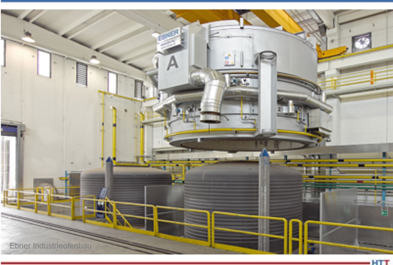






 We continue to consider the topic of natural gas pricing and reduction and its impact on heat treaters. Much of the discussion in this month’s article initially appears to deal with process quality or consistency. But understand, process consistency and energy savings are inextricably linked.