Thinking about travel plans for the upcoming holiday season? You may know what means of transportation you will be using, but perhaps you haven't considered the heat treating processes which have gone into creating that transportation.
Today’s Technical Tuesday original content round-up features several articles from Heat TreatToday on the processes, requirements, and tools to keep planes in the air and vehicles on the road, and to get you from one place to the next.
Standards for Aerospace Heat Treating Furnaces
Without standards for how furnaces should operate in the aerospace, there could be no guarantee for quality aerospace components. And without quality aerospace components, there is no guarantee that the plane you're in will be able to get you off the ground, stay in the air, and then land you safely at your destination.
In this article, written by Douglas Shuler, the owner and lead auditor at Pyro Consulting LLC, explore AMS2750, the specification that covers pyrometric requirements for equipment used for the thermal processing of metallic materials, and more specifically, AMEC (Aerospace Metals Engineering Committee).
This article reviews the furnace classes and instrument accuracy requirements behind the furnaces, as well as information necessary for the aerospace heat treater.
Dissecting an Aircraft: Easy To Take Apart, Harder To Put Back Together
Curious to know how the components of an aircraft are assessed and reproduced? Such knowledge will give you assurance that you can keep flying safely and know that you're in good hands. The process of dissecting an aircraft, known as reverse engineering, can provide insights into the reproduction of an aerospace component, as well as a detailed look into the just what goes into each specific aircraft part.
This article, written by JonathanMcKay, heat treat manager at Thomas Instrument, examines the process, essential steps, and considerations when conducting the reverse engineering process.
If you are one of the growing group of North Americans driving an electric vehicle, you may be wondering how - and how well - the components of your vehicle are produced. Electric vehicles (EVs) are on the rise, and the automotive heat treating world is on the lookout for ways to meet the demand efficiently and cost effectively. One potential solution is laser heat treating.
Explore this innovative technology in this article composed by Aravind Jonnalagadda (AJ), CTO and co-founder of Synergy Additive Manufacturing LLC. This article offers helpful information on the acceleration of EV dies, possible heat treatable materials, and the process of laser heat treating itself. Read more to assess the current state of laser heat treating, as well as the future potential of this innovative technology.
When the Rubber Meets the Road, How Confident Are You?
Reliable and repeatable heat treatment of automotive parts. Without these two principles, it’s hard to guarantee that a minivan’s heat treated engine components will carry the family to grandma’s house this Thanksgiving as usual. Steve Offley rightly asserts that regardless of heat treat method, "the product material [must achieve] the required temperature, time, and processing atmosphere to achieve the desired metallurgical transitions (internal microstructure) to give the product the material properties to perform it’s intended function."
TUS surveys and CQI-9 regulations guide this process, though this is particularly tricky in cases like continuous furnace operations or in carburizing operations. But perhaps, by leveraging automation and thru-process product temperature profiling, data collection and processing can become more seamless, allowing you better control of your auto parts. Explore case studies that apply these two new methods for heat treaters in this article.
Those familiar with vacuum heat treatments are surely acquainted with the vacuum heat treatment of titanium and how such furnaces create the ideal environment for titanium's heat treatment. However, not all titanium and its alloys are created equal. Enter the beta titanium alloy.
In this best of the web article from TAV Vacuum Furnaces, discover the potential applications for beta titanium alloys, as well as the effects that various vacuum heat treatments can have on the mechanical properties of the alloy. Additive manufacturing (AM) technologies, specifically laser powder bed fusion, are gaining increased interest in the treatment of beta titanium alloys, due to their efficiency and their cost-cutting potential. Learn more about the chemistry and applications of this unique material below.
An excerpt:
Beta titanium alloys have an unique combination of desirable properties: their high specific strengths, creep resistance, oxidation and corrosion resistance, excellent temperature resistance up to 600°C and hardenability, make them very attractive for aerospace applications. On the other hand, the excellent biocompatibility and low elastic modulus, closer to that of human bone compared to other alloys, make Ti beta alloys an excellent material for biomedical applications.
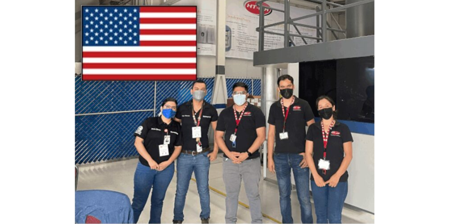
In December 2022, the first HIP batch on Latin American soil was performed. The journey to success in HIP, as any HIP user will agree, is a bumpy road. What are the challenges that aerospace manufacturers with in house heat treating should be aware of when considering HIP processing? Learn how HT-MX Heat Treat & HIPing — the heat treater who ran the first HIP batch in Latin American history — navigated the transition from small tooling jobs to HIP processing for aerospace parts.
Read the English version of the article below, or find the Spanish translation when you click the flag above right!
This original content article, first published in English and Spanish translations, is found in Heat Treat Today's March Aerospace Heat Treatingprint edition.
Writing this story as the first Latin American company to offer Nadcap accredited hot isostatic pressing brings a flood of memories and images to mind. HT-MX’s beginnings were simple, but also filled with challenges, failures, and lessons. When the company began, we were certain that, though small, we were still a “heat treat plant” and not just a shop.
Contact us with your Reader Feedback!
Being located in Mexico means that there were large companies with headquarters located far away — potential customers — that would be deciding on their heat treat supplier close to their location. We worked hard to be and to present ourselves as being very professional. But a lesson soon learned was that achieving trust with partners takes a lot more than a good speech and a clean plant.
Unsurprisingly, the first jobs were simple tooling work, like quench and tempering tooling and carburizing gears. A junior engineer and I would drive around in my old hatch-back to local machine shops and pick up a small shaft or gear and bring it back to the plant. We would get so excited when we got the case depth right.
With minimal resources, we decided to complete quality control ourselves. We became friends with a quality manager from a local company, and he came over to help on weekends and after 6:00pm until the audit date came. His knowledge is still in use at HT-MX to this day. I remember celebrating with a “Carne Asada” (a Mexican style barbecue) when we finished that first audit, thinking we had just made a huge step forward, not realizing how far away we still were from our vision.
HT-MX Team
Source: HT-MX Heat Treat & HIPing
But as time passed, we turned our attention to the aerospace industry in Chihuahua, a city with four OEMs. We received the AS9100 certification and started working on Nadcap accreditation. This required time, but by then, a pretty strong engineering team was in action, and successfully obtained Nadcap accreditation in late 2019. Again, we celebrated with a Carne Asada, this time, with a better understanding on where we were and what future challenges we needed to face.
Taking On Hot Isostatic Pressing
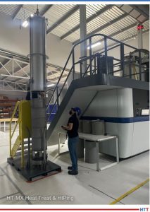
HIP system at HT-MX
Source: HT-MX Heat Treat & HIPing
The pandemic hit. Boeing’s 737 Max crisis continued to impact the industry. Moving into aerospace was slow with limited volume, especially compared to what we had seen in the automotive and oil and gas industry. But by now, international companies were more willing to transfer heat treat operations to Mexican suppliers, and we were ready, beginning with running aluminum batches, precipitation hardening, annealing, and other standard processes. It was during this early start to serve the aerospace industry that we heard about hot isostatic pressing (HIP).
Around 2019 during an aerospace cluster event, an OEM with a local presence approached us with their HIP requirements. I had only heard of HIP, but I was immediately interested — until I found out how much one of those machines cost!
But good financing through government programs helped make this HIP project a reality. Timing was not the best, as the federal election in Mexico caused a temporary Mexican currency depreciation, handicapping the project at its beginning.
Getting the proper certifications and validations proved to be a long and complex process, too. Theoretically, we knew what to expect, in terms of getting the Nadcap checklist approved, but the reality was a little different. Gaining Nadcap certification slowly builds a certain culture into any company in its day-to-day activities. Translating that culture into a completely different business unit, new crew, and new process proved to bring its own challenges.
HIP Challenges: Pressure, Temperature, Thermocouples, and Argon Supply
Heat treating usually handles temperature, atmosphere control (or lack of), and regular traceability requirements. HIP, however, adds a few new dimensions to what we usually see: internal pressure, very high temperatures — up to 3632°F (2000°C) — and argon supply. It was the first time HT-MX dealt with a process that incorporated up to 30,000 psi and also used a lot of high purity argon.
Pressure has its own challenges, though the HIP press takes care of those challenges. Still, the internal workings on these kinds of presses are fundamentally different than that of a regular heat treat furnace. Yes, you need to heat it up, but apart from that, it’s not even a furnace but a press. Understanding how the machine works, what happens inside with all that pressure, how it affects the components undergoing hot isostatic pressing, and how it affects the baskets you’re using is a critical learning curve.
High temperatures change everything about running these types of cycles. We work with metals, which means temperatures range between 1832°F and 2372°F (1000°C and 1300°C). This has an impact on thermocouple selection, calibration, and more; with the company’s thermocouple product suppliers based in the U.S., this entails more challenges and extra costs. I have lost count on those urgent same-day trips to the border to retrieve critical spares in time. It’s an 800-km/498-mi roundtrip! We have fortunately found a great supplier that has offered the technical feedback we needed, and we have started to finally understand and control our thermocouple consumption. Although, I must be honest here, we still have a lot to learn in this aspect.
Then, there’s the argon supply. HT-MX never expected it to be a challenge, but it turns out getting the proper supplier — one that understands the requirements and is willing to work with you from validation to production — is key. You might be able to start your validation process using argon transported in gas containers but eventually you will need to switch to liquid argon. That proved to be more difficult than expected. There are not many projects requiring these kind of alliances locally. Getting the right supplier was key and more of a challenge than expected. And then came the lessons on efficiently using the liquid argon, avoiding excessive venting of the tank, and being all around smart with the HIP schedule. This has been a constant learning process, one that has high costs.
Final Hurdles: Certifications, Current Events, and Energy Costs
Once our company had the Nadcap certification, we still needed to get the OEM’s approval for the HIP process, then the approval for the specific version of the HIP process, and then the actual approval for the part numbers.
These approvals were handled by the headquarters’ engineering department and not locally. It was a time-consuming process, with several test runs, lab testing, multiple audits, visits, and more testing, etc. And while all of this was happening, we still had to design the operation, locate critical suppliers not available in Mexico, create alliances with suppliers, etc. Writing this down in a few lines makes it seem simpler and quicker than it really was.
Additionally, in instances like this, Mexican companies, especially small ones, face much more scrutiny than U.S. or European-based companies, and must prove themselves in every single step. It makes sense, even if it feels a little unfair, as HT-MX had no proven track record of high tech processes such as HIP. It does cost extra time, extra care, and sometimes extra testing, but it is the reality we face and we must overcome the extra hurdles.
While navigating HIP approval, the pandemic hit. Months later, the war in Europe began with significant impacts on the cost of energy. Our main clients were high volume and low margin, and with energy prices rising, our competitiveness began to diminish. To adapt and evolve, we decided to add some smaller furnaces for smaller parts, invest in training and increased sales efforts, and focus on AMS/Nadcap-based customers, letting go of major clients. Slowly, things began to turn around.
The First Official HIP Batch in Latin America History
In December 2022, HT-MX ran the first official HIP batch in Latin American history. It was a long time coming. I always thought that running that first batch would feel like reaching the Everest summit. When the day came, it just felt like reaching Everest’s base camp. We still have a long way to go to be truly an established HIP supplier. Now, it’s back to climbing and shooting for that summit, that summit that will perpetually precede the next summit.
There are still several challenges: stabilizing new processes and improving established ones. But I am confident we will move forward in this new stage. And I am so looking forward to the next Carne Asada.
About the Author: Humberto Ramos Fernández is a mechanical engineer with a master’s degree in Science and Technology Commercialization. He has over 14 years of industrial experience and is the founder and current CEO of HT-MX Heat Treat & HIPing, which specializes in Nadcap-certifi d controlled atmosphere heat treatments for the aerospace, automotive, and oil and gas industries. With customers ranging from OEMs to Tier 3, Mr. Ramos has ample experience in developing specific, high complexity secondary processes to the highest requirements.
En diciembre de 2022, se realizó la primera horneada de HIP en suelo latinoamericano. El camino hacia el éxito en HIP, como cualquier usuario de HIP estará de acuerdo, es un camino lleno de baches. ¿Cuáles son los desafíos que deben tener en cuenta los fabricantes aeroespaciales con tratamiento térmico interno al considerar el procesamiento HIP? Aprenda directamente de HT-MX Heat Treat & HIPing, un tratador térmico que ejecutó la primera horneada de HIP en la historia de Latinoamérica, cómo navegaron la transición desde trabajos pequeños de herramentales hasta el procesamiento HIP para piezas aeroespaciales.
Read the Spanish translation of this article in the version below, or see both the Spanish and the English translation of the piece where it was originally published: Heat Treat Today's March Aerospace Heat Treating print edition.
Si quisieras aportar otros datos interesantes relacionados con HIP, nuestros editores te invitan a compartirlos para ser publicados en línea en www.heattreattoday.com. Puedes hacerlos llegar a Bethany Leone al correo bethany@heattreattoday.com
De herramientas simples al tratamiento térmico aeroespacial
Humberto Ramos Fernández Founder and CEO HT-MX
Escribir esta historia de como llegamos a ser la primera compañía latinoamericana en ofrecer prensado isostático en caliente acreditado por NADCAP trae a la mente una avalancha de recuerdos e imágenes. Los comienzos de HT-MX fueron simples, pero también llenos de desafíos, fracasos y lecciones. Cuando comenzamos la compañía, estábamos seguros de que, aunque éramos pequeños, éramos una “planta de tratamiento térmico” y no solo un taller.
Contact us with your Reader Feedback!
Estando ubicados en México quiere decir que hay grandes plantas con corporativos lejos de aquis — clientes potenciales — que estarían decidiendo sobre su proveedor de tratamiento térmico lejos de nuestra ubicación. Trabajamos arduamente para ser y presentarnos como profesionales y confiables. Pero pronto aprendimos que lograr la confi anza con los clientes requiere mucho más que un buen discurso y una planta limpia.
Como era de esperar, los primeros trabajos fueron trabajos simples de herramentales, algunos templados y revenidos de herramentales y carburizado de engranes. Recuerdo como un ingeniero junior y yo dábamos la vuelta en mi viejo hatchback alrededor de talleres locales y recogíamos un pequeño eje o engranaje y lo llevábamos de regreso a la planta. Nos emocionábamos mucho cuando lográbamos la profundidad de capa correcta.
HT-MX Team Source: HT-MX Heat Treat & HIPing
Con recursos mínimos, decidimos implementar el sistema de calidad nosotros mismos. Nos hicimos amigos de un gerente de calidad de una empresa local, venía a ayudarnos los fines de semana o después de las 6:00 p.m. hasta que llegó la fecha de la auditoría. Su enseñanzas aún se usan en HT-MX hasta el día de hoy. Recuerdo celebrar con una “Carne Asada” cuando terminamos esa primera auditoría, pensando que habíamos dado un gran paso adelante, sin darme cuenta de lo lejos que aún estábamos de nuestra visión.
Con el tiempo, dirigimos nuestra atención a la industria aeroespacial en Chihuahua, una ciudad con cuatro OEMs. Recibimos la certificación AS9100 y comenzamos a trabajar en la acreditación NADCAP. Esto requirió tiempo, pero para entonces contábamos con un equipo de Ingenieros bastante sólido y obtuvimos con éxito la acreditación de NADCAP a finales de 2019. Nuevamente, celebramos con una Carne Asada, esta vez con una mejor comprensión de dónde estábamos y qué futuros desafíos tendríamos que enfrentar.
Entrándole al Prensado Isostático en Caliente
La pandemia llegó. La crisis del 737 Max de Boeing continuó afectando a la industria. Empezar en sector aeroespacial fue lento y con un volumen limitado, especialmente en comparación con lo que habíamos visto en la industria automotriz y de oil&gas. Pero para entonces, las empresas internacionales estaban más dispuestas a trasladar las operaciones de tratamiento térmico a proveedores mexicanos, y estábamos listos, comenzando a procesar aluminio, endurecimiento por precipitación, recocido y otros procesos estándar. Fue durante estos inicios en la industria aeroespacial que escuchamos hablar del prensado isostático en caliente (HIP) por primera vez.
Alrededor de 2019, durante un evento del Cluster Aeroespacial de Chihuahua, un OEM con presencia local se acercó a nosotros con sus requerimientos de HIP. No conocíamos mucho de HIP, pero de inmediato me interesé . . . ¡hasta que descubrí cuánto cuesta una de esas máquinas!
Pero un buen financiamiento a través de programas gubernamentales ayudó a hacer realidad este proyecto de HIP. El momento no fue el mejor, ya que las elecciones federales en México causaron una depreciación temporal de la moneda mexicana, lo que obstaculizó el proyecto al principio.
HIP system at HT-MX Source: HT-MX Heat Treat & HIPing
Obtener las certificaciones y validaciones adecuadas resultó ser un proceso largo y complejo también. Teóricamente, sabíamos qué esperar en términos de obtener la aprobación para el checklist de NADCAP, pero la realidad fue un poco diferente. Obtener la certifi cación de NADCAP construye lentamente una determinada cultura en cualquier empresa en sus actividades diarias. Traducir esa cultura a una unidad de negocio completamente diferente, con un nuevo equipo y un nuevo proceso, demostró traer sus propios desafíos.
Retos en el HIP: presión, temperatura, termopares y argon
El tratamiento térmico generalmente trata de temperatura, control de la atmósfera (o la falta de ella) y los requisitos regulares de trazabilidad. HIP, sin embargo, agrega algunas dimensiones nuevas a lo que normalmente vemos: presión interna, temperaturas muy altas, de hasta 3632°F (2000°C) y suministro de argón. Fue la primera vez que HT-MX lidiaba con un proceso que incorporaba hasta 30,000 psi y también usaba mucho argón de alta pureza.
La presión tiene sus propios desafíos, aunque la prensa de HIP se encarga de ellos. Aún así, el funcionamiento interno en este tipo de prensas es fundamentalmente diferente al de un horno de tratamiento térmico regular. Sí, necesitas calentarlo, pero aparte de eso, no es ni siquiera un horno, sino una prensa. Comprender cómo funciona la máquina, qué sucede dentro con toda esa presión, cómo afecta a los componentes sometidos a prensado isostático en caliente y cómo afecta a las canastas y fi xtures que estás utilizando, es una curva de aprendizaje crítica.
Las altas temperaturas cambian todo sobre el funcionamiento de estos tipos de ciclos. Trabajamos con metales, lo que significa que las temperaturas oscilan entre 1832°F y 2372°F (1000°C y 1300°C). Esto tiene un impacto en la selección de termopares, calibración y más; con los proveedores de termopar basados en EUA, esto implica más desafíos y costos adicionales. He perdido la cuenta cuantos viajes urgentes de ida y vuelta por refacciones a la frontera he hecho. ¡Es un viaje redondo de 800 km! Afortunadamente, hemos encontrado un gran proveedor que nos ha ofrecido la retroalimentación técnica que necesitábamos, y finalmente hemos comenzado a comprender y controlar nuestro consumo de termopares. Aunque, debo ser honesto aquí, todavía tenemos mucho que aprender en este aspecto.
Luego está el suministro de argón. En HT-MX nunca esperamos que fuera un desafío, pero resulta que conseguir el proveedor adecuado, un que entienda los requisitos y esté dispuesto a trabajar contigo desde la validación hasta la producción, es clave. Es posible que puedas iniciar tu proceso de validación usando argón transportado en contenedores de gas, pero eventualmente necesitarás cambiar a argón líquido. Eso resultó ser más difícil de lo esperado. No hay muchos proyectos que requieran este tipo de alianzas a nivel local. Conseguir el proveedor adecuado fue clave y resultó ser un desafío mayor de lo esperado. Y luego vinieron las lecciones sobre cómo utilizar eficientemente el argón líquido, evitar el excesivo venteo del tanque y ser inteligente con el calendario de HIP en general. Esto ha sido un proceso de aprendizaje constante, uno que tiene altos costos.
Últimos obstáculos: certificaciones, eventos globales y costos energéticos
Una vez que nuestra empresa obtuvo la certificación NADCAP, todavía necesitábamos la aprobación de los OEM para el proceso HIP, luego la aprobación para la versión específica del proceso HIP y luego la aprobación real para los números de parte.
Estas aprobaciones fueron manejadas por el departamento de ingeniería del corporativo y no localmente. Fue un proceso que consumió mucho tiempo, con varias pruebas, pruebas de laboratorio, múltiples auditorías, visitas y más pruebas, etc. Y mientras todo esto sucedía, todavía teníamos que diseñar la operación, localizar proveedores críticos que no estaban disponibles en México, crear alianzas con proveedores, etc. Escribir esto en pocas líneas parece más simple y rápido de lo que realmente fue.
Además, en casos como este, las empresas mexicanas, especialmente las pequeñas, enfrentan mucho más escrutinio que las empresas estadounidenses o europeas, y deben probarse en cada paso. Tiene sentido, aunque se siente un poco injusto, ya que HT-MX no tenía un historial comprobado de procesos de alta tecnología como HIP. Cuesta tiempo extra, cuidado adicional y a veces pruebas adicionales, pero es la realidad que enfrentamos y debemos superar los obstáculos adicionales.
Mientras navegábamos en la aprobación de HIP, llegó la pandemia. Meses después, comenzó la guerra en Europa con impactos significativos en el costo de la energía. Nuestros principales clientes eran de alto volumen y bajo margen, y con el aumento de los precios de la energía, nuestra competitividad comenzó a disminuir. Para adaptarnos y evolucionar, decidimos agregar algunos hornos más pequeños para piezas más pequeñas, invertir en capacitación y aumentar los esfuerzos de ventas y enfocarnos en clientes basados en AMS / NADCAP, dejando ir a clientes principales. Poco a poco, las cosas comenzaron a mejorar.
La Primera Horneada Ofi cial de HIP en la Historia de Latinoamérica
En diciembre de 2022, HT-MX llevó a cabo la primera horneada oficial de HIP en la historia de Latinoamérica. Tomo bastante tiempo. Siempre pensé que hacer esa primera horneada se sentiría como llegar a la cima del Everest. Cuando llegó el día, solo se sintió como llegar al campamento base del Everest. Todavía nos queda mucho camino por recorrer para ser realmente un proveedor de HIP establecido. Ahora, volvemos a escalar y apuntamos a esa cima, esa cima que perpetuamente precederá a la próxima cima.
Todavía hay varios desafíos: estabilizar nuevos procesos y mejorar los establecidos. Pero estoy seguro de que avanzaremos en esta nueva etapa. Y estoy muy emocionado por la próxima Carne Asada.
Acerca del Autor:Humberto Ramos Fernández es un ingeniero mecánico con una maestría en Ciencia. Tiene más de 14 años de experiencia industrial y es el fundador y actual CEO de HT-MX Heat Treat & HIPing, que se especializa en tratamientos térmicos de atmósfera controlada, con certifi cación NADCAP, para las industrias aeroespacial, automotriz y de petróleo y gas. Con clientes que van desde OEM hasta Tier 3, el Sr. Ramos tiene una amplia experiencia en el desarrollo de procesos secundarios específi cos de alta complejidad para los requisitos más exigentes.
What is the connection between AMS2750 specifications and furnace classifications? With tight specifications, what does the heat treater need to know to be compliant? Follow along as we take a brief look into this often-overlooked topic.
This Technical Tuesday article, written by Douglas Shuler, owner and lead auditor, Pyro Consulting LLC, was first published in Heat Treat Today's March 2023 Aerospace Heat Treating print edition.
Doug Shuler Lead Auditor Pyro Consulting
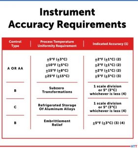
AMS2750 is the specification that covers pyrometric requirements for equipment used for the thermal processing of metallic materials. AMEC (Aerospace Metals Engineering Committee) is one of the committees which oversees the changes and revisions of AMS2750. There are five main sections in the technical requirements of the specification: sensors, instrument calibrations, thermal processing classification, SAT (system accuracy testing), and TUS (temperature uniformity surveys). Additionally, there are quality provisions that detail what happens if a calibration or test is either past due or fails.1
Contact us with your Reader Feedback!
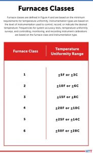
Revisions to the original requirements have occurred over the years, with the newest being Revision G. The structure of Revision G has carried over from Revision F and has remained the current structure of the AMS2750 specification. This structure includes furnace classes, which are based on the minimum requirements for temperature uniformity.
Furnace classes are defined in Figure A of Revision D Figure 1.
Figure 1. AMS2750G furnace class uniformity tolerances Source: Doug Shuler
Originally, furnace classes were based on temperature uniformity, but also subzero transformation, refrigerated storage of aluminum alloys, and embrittlement relief, Figure 2.
Figure 2. Original AMS2750 instrument accuracy requirements, no class structure Source: Doug Shuler
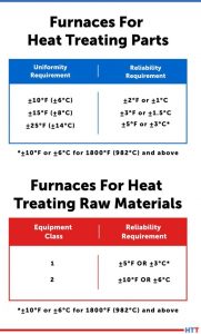
AMS2750 Revision C was released in May 1990 and started to implement the class and instrumentation type structure and differentiated between furnaces for heat treating parts versus furnaces for heat treating raw materials. Furnaces for heat treating parts were classified based on uniformity, but also on a readability requirement. Furnaces for heat treating raw materials were classified based on a readability requirement alone.
AMS2750 Revision D was released in September 2005 and continued to define equipment class (Figure A)* and instrumentation type (Section 3.3.1.1)*. It also clarified chart recorder resolution (Table 4)*, print and chart speed (Table 5)*, and testing frequencies for SAT (Tables 6, 7)* and TUS (Tables 8, 9)* for the processing of parts versus raw materials.
AMS2750 Revision E was released in July 2012 and continued to build on the clarity presented in Revision D by adding an instrumentation type table (Figure 3)* instead of a simple text description in the body of the specification.
Figure 3. AMS2750 Revision C: distinguishment between furnaces for heat treating parts versus raw materials Source: Doug Shuler
Moving to AMS2750 Revision F, the specification saw a major rewrite and restructuring where the tables were moved from the end of the document to the first area text that called out the specific table. Revision F also put into place a sunset date for analog instruments.
That brings us to the current revision of AMS2750, Revision G, which has carried forward the structure of Revision F and only sought to further clarify the intent of the requirements.
Over the years, the technology of sensor, instrument, and furnace manufacture and capability has continued to produce better and tighter controls for the process of heat treating. The evolution of AMS2750 has recognized these advancements and has kept pace with them in technology. The understanding of the origins of AMS2750 and how it has evolved is vital in understanding its application to today’s heat treat special processes.
*Specified figure, table, or section is associated with the AMS2750 revision being discussed.
About the Author: In 2009, Douglas (Doug) Shuler became the owner of Pyro Consulting LLC and also began working with Performance Review Institute (PRI), first as an instructor and course developer and later as an auditor for the Nadcap program. As a lead auditor for Nadcap, he has conducted over 380 Nadcap special process and aerospace quality management system audits on behalf of the Aerospace Primes over the past 10+ years. Doug continues to focus on instruction, training, and education for the heat treat industry, developing courses, authoring exams, and employing the PIE method: “Procedures that Include all requirements, and Evidence to show compliance.”
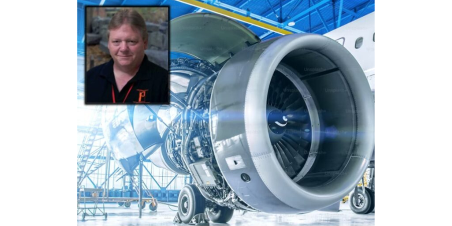
What are the factors that lead to carburization and carbon transmission? How can heat treater avoid these unwanted reactions? Discover the challenges of CFC fixtures and the steps heat treaters can take to mitigate these challenges.
This Technical Tuesday article, written by Dr. Jorg Demmel, founder, 0wner, and president, High Temperature Concept, was first published in Heat Treat Today's March 2023 Aerospace Heat Treating print edition.
Introduction
Dr. Jorg Demmel Founder, Owner, President High Temperature Concept
The main advantages of CFC fixtures were introduced in “CFC Fixture Advantages and Challenges in Vacuum Heat Treatment, Part 1,” which was released in Heat Treat Today’s November 2022 publication. This included a discussion of the limits of CFC in vacuum and protective atmosphere heat treatment. Successful applications of CFC workpiece carriers in heat treatment were presented along with field test results that included a brief discussion of undesired contact reactions (i.e., carburization and melting of parts). In Part 2 of this paper, the mechanisms involved with carburization and carbon transmission due to direct contact of parts with CFC fixtures will be further explained.
Mass Transfer from CFC Fixtures
Contact us with your Reader Feedback!
The mass transport of carbon from CFC fixtures into steel parts at high temperatures will be examined in the following areas:
Reactions in oxygen (i.e., the reaction medium)
Transport of carbon in CFC during exposure to oxygen
Transfer mechanism into the steel parts
Diffusion of carbon into the steel parts
Part reactions (melting, carbide formation)
Figure 1: 1.6582 steel samples and GDEOS depth profile analysis Source: Dr. Jorg Demmel, High Temperature Concept
CFC samples were tested in contact with steel samples under laboratory conditions in a vacuum of 7.5 x 10⁻⁷ Torr (1 x 10⁻⁶mbar). Results of the contact with CFC for steel samples at different temperatures are presented to the left (Figure 1). It is important to note that:
Sample (0) is the reference sample and had no exposure to the contact test.
Sample (0’) is the back side of Sample (0).
Sample (1) is the contact side at 1922°F (1050°C).
All three samples are visually identical, therefore only one is shown. Sample (2) at 1967°F (1075°C) and Sample (3) at 2012°F (1100°C) exhibited a distinct visual surface pattern after CFC contact. This was analyzed by Glow Discharge Optical Emission Spectroscopy (GDOES) and the test location (gray spot) clearly observed on Samples (2) and (3). For Sample (4) run at 2057°F (1125°C), the CFC was found to have adhered to the steel surface.
The carbon content in 10mm depth measured with GDOES (see the profiles in Figure 1) increased from initially 0.29 weight-% for the 1922°F (1050°C) test, although nothing was visible on metal surfaces. For carbon contents, see Table 1.
Table 1. Carburizing of 1.6582-samples in 10 µm depth after CX-27C1-contact (GDOES) Source: Dr. Jorg Demmel, High Temperature Concept
CFC Reactions with Oxygen
The chemical reactions of CFC with various gases are essential in Step 1 (referenced in Part 1 of this article) and an indicator of chemical thermal suitability.
In the case of the unwanted contact carburization considered above is similar, in a sense, to carburization of steel in contact with carbon powder or granulate. However, the actual carburization mechanism, which occurs between approximately 1616°F and 1697°F (880°C and 925°C), does not take place directly via the carbon contact but is based on the fact that solid carbon reacts with atmospheric oxygen according to the Equation Table to form carbon dioxide (CO2).
Equation Table. Reaction rates and activation energies for graphite (800°C; 0.1 bar) Source: Dr. Jorg Demmel, High Temperature Concept
Carbon monoxide (CO) is then formed from CO2 by the Boudouard reaction (Equation 3). At high temperatures and low pressures (see Figure 2), almost only CO is present.
Figure 2. Boudouard equilibrium Source: Dr. Jorg Demmel, High Temperature Concept
Transport of Carbon
The carbon carrier must be transported to the surface of the parts.
The cases considered in Part 1 of this article were conducted in vacuum, that is in the absence of a carburizing atmosphere. The laboratory tests were even carried out in a vacuum as low as 7.5 x 10⁻⁷ Torr (1 x 10⁻⁶mbar). Nevertheless, part surface reactions were observed.
Transfer Mechanism into the Steel Parts
Theoretically, carbon from the CFC fixtures can be transferred into the steel via solid phase (as opposed to gaseous phase) reactions. Gas particles can be adsorbed by surfaces via physisorption and/or chemisorption. The author’s personal research experience has shown that metal samples usually oxidize after a short time, even in a high vacuum of 7.5 x 10⁻⁷ Torr (1 x 10⁻⁶mbar). In particular, elements such as iron, molybdenum, and chromium have a strong ability to chemically adsorb oxygen or CO.
Furthermore, there is a disproportionately large amount of adsorbed oxygen in the CFC samples. CFC has open porosities as high as 30%. CFC in industrial practice is never completely evacuated. So, there is a disproportionately large amount of oxygen present in CFC fixtures.
It can be assumed that oxygen repeatedly escapes from the CFC and is initially available in the contact area. Proof of this can be provided by the GDOES analysis. Outside the contact areas, no (gas) carburization took place (as evidenced by the non-contact side of steel samples).
The oxygen and carbon surplus combined with close contact lead to complete reaction of oxygen creating carbon dioxide as in Equation (1). Because of the carbon surplus, almost only carbon monoxide is produced as shown in Equation (2). Because of the very close contact between CFC and steel, C-adsorption by gamma iron and desorption of carbon dioxide as in Equation (5) takes place:
Equation 5 Source: Dr. Jorg Demmel, High Temperature Concept
Since carbon dioxide immediately comes in contact with carbon in the CFC again, carbon monoxide is produced according to Equation (3). In other words, carbon dioxide regenerates immediately and the reaction starts again.
Direct carbon transfer from CFC to metal via solid phase is very unlikely since carbon atoms in CFC are firmly bound in rings.
Diffusion of Carbon in the Steel Parts
In solids, the surface diffusion usually takes place at significantly higher diffusion rates than in the bulk material. The thermodynamic driving force of diffusion or carburizing reactions is the difference in carbon activity for a specific concentration in the austenite to that of the reaction medium. The carbon activity is the ratio of the vapor pressure of the carbon in state under consideration to vapor pressure of pure carbon (graphite/CFC). Alloying elements of the steel influence the activity of the carbon.
Part Reactions (Melting and Carbide Formation)
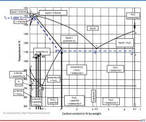
Steel can begin to melt if, at the given values for temperature and pressure, a partially liquid phase is reached, that is, the solidus line in the phase diagram is exceeded. At even higher temperatures, the liquidus temperature can be reached and steel is completely liquid.
According to metastable iron-carbon diagram phase diagram (Figure 3), a steel such as SAE/ AISI 4340 (34CrNiMo6) alloy (DIN 1.6582) with around 0.47% by weight percent carbon does not begin to melt at 1922°F (1050°C), the exposure temperature for Sample (1), or Sample (2) at 0.56% and 1967°F (1050°C) for Sample (3) with 0.67% for 2012°F (1100°C). The iron-iron carbide phase diagram applies to steels with less than 5% (by mass) of alloying elements and thermodynamic equilibrium, so it is an accurate representation for a SAE/AISI 4340 (34CrNiMo6) alloy.
Figure 3. Metastable equilibrium diagram Fe-Fe3C for steel (good fit for 1.6582) Source: Dr. Jorg Demmel, High Temperature Concept
A calculation of the solidus temperature shown on the iron-iron carbide diagram (Figure 3), which is dependent on the carbon content and alloying elements, yields a value of 2703.2°F (1,484°C) (J’).
For an SAE/AISI 4340 (34CrNiMo6) steel (DIN 1.6582) with 0.3% C and one for 0.5% C, the calculated solidus temperature is 2640°F (1449°C). This is shown on the J’-E’ blue dotted line in Figure 3. In other words, a lower solidus line (cf. dashed blue line in Figure 3) and thus a slight reduction in austenite phase region.
The iron-carbon diagram also indicates that melting of surfaces that have absorbed carbon (e.g., Sample No. 2) will occur at 1967°F (1075°C). This value is within approximately 90°F (50°C) of the temperature used (dotted line E’-C’-F’). From this information we can conclude that the observations seen in Figure 1 are not the result of melting, but rather imprints due to surface softening.
The melting (c.f., Figure 1) observed in Test No. 4, which occurred at 2057°F (1125°C) is likely due to partial carburization of the steel surface and exceeding the solidus temperature. A micrograph confirms eutectic melting and high carbon content, which could also be indirectly confirmed by hardness measurement.
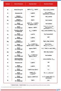
Carbide Formation
Additional reactions can occur between carbon absorbed from the CFC fixtures and the steel parts due to either separation of carbides (e.g., iron carbide in the form of secondary cementite) or carbide formation with alloying elements such as Ti, V, Mo, W, Cr, or Mn (listed in decreasing tendency to form carbides).
Table 2. Reactions between C and metal Source: Dr. Jorg Demmel, High Temperature Concept
Table 2 lists various elements in alphabetical order that react with carbon above the specified temperatures to form reaction products mentioned, primarily carbides. It should be noted that the temperatures listed apply only to pure metals and pure carbon. As such, they provide only rough approximations of a temperature at which a reaction might begin.
Countermeasures
There are several measures to avoid these unwanted reactions:
Ceramic oxide coatings such as aluminum oxide (Al2O3) or zirconium oxide (ZrO2) layers placed onto the CFC
Hybrid CFC fixtures having ceramics in key areas to avoid direct contact with metal workpieces
Alumina composite sheets
Boron nitride sprays
Special fixtures made of oxide ceramics
An yttrium-stabilized zirconium oxide layer (93/7) was applied to CF222 by thermal plasma spray and tested successfully (see Figure 4).
Figure 4. Yttrium-stabilized zirconium oxide layer with an average layer thickness of 110µm on CF222 material. The photograph on the right shows a hybrid CFC fixture. Source: GTD Technologie Deutschland
Summary
It is important to consider the specific process conditions in advance so that unwanted reactions — from carburization to catastrophic melting of the workpieces — can be avoided. Effective countermeasures can be taken.
References
Atkins, P. W.: Physikalische Chemie. 1. vollst. durechges. u. berichtigter Nachdr.d. 1. Aufl ., Weinheim, VCHVerlag, 1988 – ISBN 3-527-25913-9.
Bürgel, R.: Handbuch Hochtemperatur-Werksto technik: Grundlagen, Werksto bean-spruchungen, Hochtemperaturlegierungen. Braunschweig, Wiesbaden: Vieweg, 1998. ISBN 3-528-03107-7.
Demmel, J.: Advanced CFC-Fixture Applications, their scientific challenges and economic benefits, In: 30th Heat Treating Society Conference & Exposition, Detroit, MI, USA, 15th Oct. 2019.
Demmel, J.: Werkstoffwissenschaftliche Aspekte der Entwicklung neuartiger Werkstückträger für Hochtemperaturprozesse aus Faserverbundkeramik C/C und weiteren Hochtemperaturwerkstoffen, Dissertation, TU Freiberg, Germany, 2003.
Demmel, J.: Why CFC-Fixtures are a Must for Modern Heat Treaters, FNA 2020 Technical Session Processes & Quality, USA, 30th Sept. 2020.
Demmel, J., et al: Applications of CMC-racks for high temperature processes. In: 4th Int. Conf. on High-Temperature Ceramic Matrix Composites, 3.10.2001, p. A-17.
Demmel, J. und J. Esch: Handhabungs-Roboter sorgt für Wettbewerbsvorsprung. Härterei: Symbiose von neuen Werkstoffen und Automatisierung. In: Produktion (1996), No. 16, p. 9.
Demmel, J. und U. Nägele: CFC revolutioniert die Wärmebehandlung. In: 53. Härterei-Kolloquium, Wiesbaden, 10.10.97. Vortrag und Tagungsbericht.
Demmel, J., Lallinger, H.: CFC-Werkstückträger revolutionieren die Wärmebehandlung. In: Härtereitechnische Mitteilungen 54, No. 5, p. 289-294, 1999.
Eckstein, H.-J., et al: Technologie der Wärmebehandlung von Stahl. 2nd Edition, VEB Deutscher Verlag für Grundstoffindustrie, Leipzig, 1987. ISBN 3-342-00220-4.
Godziemba-Maliszewski, J.; Batfalsky, P.: Herstellung von Keramik-Metall-Verbindungen mit Diffusionsschweißverfahren. In: Technische Keramik, Jahrbuch, Essen, 1 (1988), S. 162-172. ISBN 3-80272141-1.
Grosch, J.: Grundlagen-Verfahren-Anwendungen-Eigenschaften einsatzgehärteter Gefüge und Bauteile, ExpertVerlag, 1994, ISBN 3-8169-0739-3.
Hollemann, A.F.; Wiberg, E.: Lehrbuch der anorganischen Chemie / Hollemann-Wiberg. 91.-100. Aufl ., de Druyter Verlag, 1985 – ISBN 3-11-007511-3.
Kriegesmann, J.: Technische Keramische Werkstoffe. Loseblattwerk mit 6 Ergänzungslieferungen pro Jahr.
Kussmaul, K.: Werkstoffkunde II. Stuttgart, Universität, Lehrstuhl für Materialprüfung, Werkstoffkunde und Festigkeitslehre, Vorlesungsmanuskript, 1993.
Lay, L.: Corrosion Resistance of Technical Ceramics. 1. Aufl ., Teddington, Middlesex, Crown-Verlag, 1983 – ISBN 0-11-480051-0.
Marsh, H.; u.a.: Introduction to Carbon Science. 1. Aufl ., London, Butterworths-Verlag, 1989 – ISBN 0-40803837-3.
Spur, G.: Wärmebehandeln. Berlin, 1987, ISBN 3-446-14954-6.
Samsonow, G.V.: Handbook of refractory compounds. New York, 1980.
Schulten, R.: Untersuchungen zum Kohlenstofftransportmit Carbidbildung in Nickelbasis-legierungen. RWTH Aachen, Fakultät für Maschinenbau, Diss., 1988 Deutsche Keramische Gesellschaft, 1990 following. ISBN 3-87156-091-X.
About the Author: Dr. Jorg Demmel is the founder, owner, and president of High Temperature Concept. He received his Engineering Doctorate in the field of CFC workpiece carriers for heat treatment and served in different leading positions for Volkswagen before moving to the U.S. In this article, Demmel draws on his dissertation, “Material scientific aspects of the development of new Fixtures for high temperature processes made of fiber-composite ceramics C/C and other high temperature materials” (Technical University Mining Academy Freiberg, Germany, 2002/3), and his personal experiences. For more information, contact Jorg at jorg.demmel@high-temperature-concept.com
Find heat treating products and services when you search on Heat Treat Buyers Guide.com
You can take the aircraft apart, but can you put it back together? Reverse engineering, as anyone who has ever taken apart the TV remote will tell you, is more complicated than it first appears. It is, however, far from impossible. Learn the essential steps to reverse engineering, the role of heat treating, and the challenges the thought process presents.
For this Technical Tuesday piece, take a few minutes to read Jonathan McKay's, heat treat manager at Thomas Instrument, article drawn from Heat Treat Today's March Aerospace Heat Treating print edition. Heat Treat Today is always pleased to share pieces from one of our 40 Under 40 alumnus like Jonathan!
If you want to share ideas about the aerospace industry, our editors would be interested in featuring it online at www.heattreattoday.com. Email Bethany Leone at bethany@heattreattoday.com with your own contributions!
Contact us with your Reader Feedback!Jonathan McKay
Heat Treat Manager at Thomas Instrument
Source: Thomas Instrument
Reverse engineering (RE) is the process of taking a component or design and dissecting it all the way down to the raw material. Reverse engineering can range from a singular component such as a piston or gear, to multiple components that make up an overall assembly such as an engine or mechanical actuator. This process allows engineers to analyze and gain an understanding of a component’s overall function and design through deductive reasoning. RE can range in the type of analysis, from geometric measurements and material analysis to electrical or mechanical testing. Each analysis reveals clues of how something can be reproduced. The idea of reverse engineering is to look beyond what’s in front of you and find the unexposed clues that can show why something was designed or possibly the thought process of the original designer.
Reverse engineering typically happens through a third-party manufacturer usually not affiliated with the original equipment manufacturer (OEM). Often this is done because the original manufacturer no longer supports the product, or the original design is outdated and needs to be modernized to improve efficiency, functionality, or life expectancy. To put this in perspective, the U.S. Airforce received its first B-1 Bomber in 1984. Since then, over 100 aircrafts have been delivered. After nearly 50 years the aircraft is still flying, but many OEM manufacturers have moved on to newer programs, thus allocating their capabilities and capacity towards the present and future market demands. This creates a market for fabrication of replacement components and assemblies to support aging platforms. In most cases, the OEM’s retain proprietary data thus creating a need for RE processing.
"[T]he U.S. Airforce received its first B-1 Bomber in 1984.
Source: Unsplash.com/midkiffaries
With aerospace products in particular and specifically aging aircrafts, one will encounter obsolescence issues. The goal is to maintain the aircraft with replacement parts that conform to all form, fit, and function requirements while also assuring they have proper life expectancy with respect to maintenance cycles. With this in mind, you typically work with low volume production and invest more time into the design and planning phase of the process. When engaged in this process, it is critical that one understands and implements a fabrication plan that will yield a product that is equivalent or better than that of the OEM. Some engineers would say “Well, let’s make it bigger and better,” but with aerospace components this is not always the case. Typically, the main focus is to replicate the original design intent to the best of your ability because you have a specific footprint and weight to maintain as well as functionality. The exchangeability of the original design and RE design is key. The reverse engineered product needs to possess the same functional and physical characteristics and be equivalent in the performance, reliability, and maintainability. This allows both items to be exchanged without concern for fi t, performance, or alterations to its adjoining component(s).
Another key point in RE processing could be to limit long lead phases by minimizing the need for additional qualification testing where possible. As plating, heat treat, or materials begin to deviate from the initial design, you must consider requalification testing to prove those changes are not detrimental to the application and do not cause more harm than good. Sometimes engineers create features within a design that are meant to be a weak point; this prevents a more critical component from breaking or being destroyed. When you begin to make deviations, it may push the weak point closer to the critical component.
While there are certainly many steps to RE, the essential steps include:
Collect as much data as possible from an external standpoint without destroying or disassembling; i.e., note the overall measurements, orientation, special features, electrical or mechanical properties, etc. It is also a good idea to analyze mating components and/or the system in which the component is utilized. Mating parts are a big part of the discovery; the mating parts can help determine what alternate materials, plating, heat treat, or finishes can be used.
Start creating preliminary drawings with detailed dimensions, notes, and features that were inspected from Step 1.
Slowly disassemble the part (if an assembly) and inspect key features and create preliminary drawings for sub-assembly components. In some cases, it helps to reassemble the product to ensure an understanding of how it goes back together in order to optimize the assembly process once new components are manufactured.
Evaluate the product(s). Conduct material analysis to acquire chemical and mechanical property data. This will aid in defining the appropriate layout for machining, material conditioning (i.e., heat treatment), external finishes/coatings, etc.
While the design and planning phase may pose some challenges, the more critical challenges that occur during reverse engineering are in the execution of the manufacturing, assembly, and qualification testing. To elaborate, once you begin machining and processing components, there may be special methods of manufacturing that require discovery because standard methods may not have worked when the OEM produced it. When this happens, you go back and forth on updating and fine-tuning the process plans, fixturing, programs, etc. Sometimes this means scrapping parts and starting over or validating if parts are still usable for prototyping. Along the same lines, when the process progresses into the assembly and testing phase, engineers typically discover variability, errors, or weak points that require adjustments. In those cases, the engineer’s drawings must be revised. A large percentage of these issues can be limited through experience with similar components or assemblies, but in most cases, there is a lot of analysis and some trial-and error involved in the manufacturing, assembly, and testing phase that is not apparent upon initial RE processing.
References:
Boeing. “The Bone.” https://www. boeing.com/defense/b-1b-bomber/
DLA. “Master List of Technical and Quality Requirements Version 14.”
MIL-STD-280A. “Handbook for definitions of item levels, item exchangeability, models, and related terms.”
DOD Washington, D.C. 20301.
Special thanks to David V. Jones and Thomas R. Blackburn IV at Thomas Instrument for their input on this topic.
About the Author:
Jonathan McKay is a mechanical engineer at Thomas Instrument, a company specializing in reverse engineering critical aerospace components. At the company, he is manning the establishment of heat treat operations, has created procedures and process plans for Thomas Instrument to be an approved heat treater for an aerospace prime, and has attained Nadcap accreditation for heat treat.
Vacuum furnaces are widely used in the aerospace and automotive industries. These furnaces are used for multiple processes including brazing, aging, and solution heat treating for countless materials. Typically, vacuum furnaces are utilized to ensure a lack of oxidation/contamination during heat treatment. This article will talk about the origins, theory, and main parts of vacuum technology and how it is used in both aerospace and automotive industries.
This Technical Tuesday feature was written by Jason Schulze, director of technical services at Conrad Kacsik Instrument Systems, Inc., and was first published in Heat Treat Today's December 2022 print edition.
A Brief History
Vacuum furnaces began to be used in the 1930s for annealing and melting titanium sponge materials. Early vacuum furnaces were hot wall vacuum furnaces, not cold wall vacuum furnaces like we use today. Additionally, most early vacuum furnaces did not utilize diffusion pumps.
Vacuum Heat Treat Theory
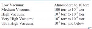
Vacuum technology includes vacuum pumping systems which enable the vessel to be pulled down to different stages through the process. Degrees of vacuum level are expressed opposite of pressure levels: high vacuum means low pressure. In common usage, the levels shown below in Figure 1 correspond to the recommendations of the American Vacuum Society Standards Committee.
Vacuum level will modify vapor pressure in a given material. The vapor pressure of a material is that pressure exerted at a given temperature when a material is in equilibrium with its own vapor. Vapor pressure is a function of both the material and the temperature. Chromium, at 760 torr, has a vapor pressure of ~4,031°F. At 10¯5, the vapor pressure is ~2,201°F. This may cause potential process challenges when processing certain materials in the furnace. As an example, consider a 4-point temperature uniformity survey processed at 1000°F, 1500°F, 1800°F, and 2250°F. This type of TUS will typically take 6-8 hours and, as the furnace heats up through the test temperatures, vacuum readings will most likely increase to a greater vacuum level. If expendable Type K thermocouples are used, there is a fair chance that, at high readings, you may begin to have test thermocouple failure due to vapor pressure.
Figure 1. Vacuum levels corresponding to the recommendations of the American Vacuum Society Standards Committee
Source: Jason Schulze, Conrad Kacsik Instrument Systems, Inc.
Vacuum Furnace Pumping System
Vacuum heat treating is designed to eliminate contact between the product being heat treated and oxidizing elements. This is achieved through the elimination of an atmosphere as the vacuum pumps engage and pulls a vacuum on the vessel. Vacuum furnaces have several stages to the pumping system that must work in sequence to achieve the desired vacuum level. In this section we will examine those states as well as potential troubleshooting methods to identify when one or more of those stages contributes to failure in the system.
Vacuum furnaces have several stages to the pumping system that must work in sequence to achieve the desired vacuum level. Each pump within the system has the capability to pull different vacuum levels. These pumps work in conjunction with each other (see Figure 2).
Figure 2. Vacuum pumps work in conjunction with one another
Source: Jason Schulze, Conrad Kacsik Instrument Systems, Inc.
The mechanical pump is the initial stage of vacuum. This pump may pull from 105 to 10. At pressures below 20 torr the efficiency of a mechanical pump begins to decline. This is when the booster pump is initiated.
The booster pump has two double-lobe impellers mounted on parallel shafts which rotate in opposite directions (see Figure 3).
Figure 3. Booster pump positions
Source: Jason Schulze, Conrad Kacsik Instrument Systems, Inc.
The diffusion pump (Figure 4) is activated into the pumping system between 10 and 1 microns. The diffusion pump allows the system to pump down to high vacuum and lower. The diffusion pump has no moving parts.
Figure 4. Diffusion Pump
Source: Jason Schulze, Conrad Kacsik Instrument Systems, Inc.
The pump works based on the vaporization of the oil, condensation as it falls, and the trapping and extraction of gas molecules through the pumping system.
Image 1. Holding Pump
Source: Jason Schulze, Conrad Kacsik Instrument Systems, Inc.
The holding pump (Image 1) creates greater pressure within the fore-line to ensure that, when the crossover valve between the mechanical and diffusion pump is activated, the oil within the diffusion pump will not escape into the vessel.
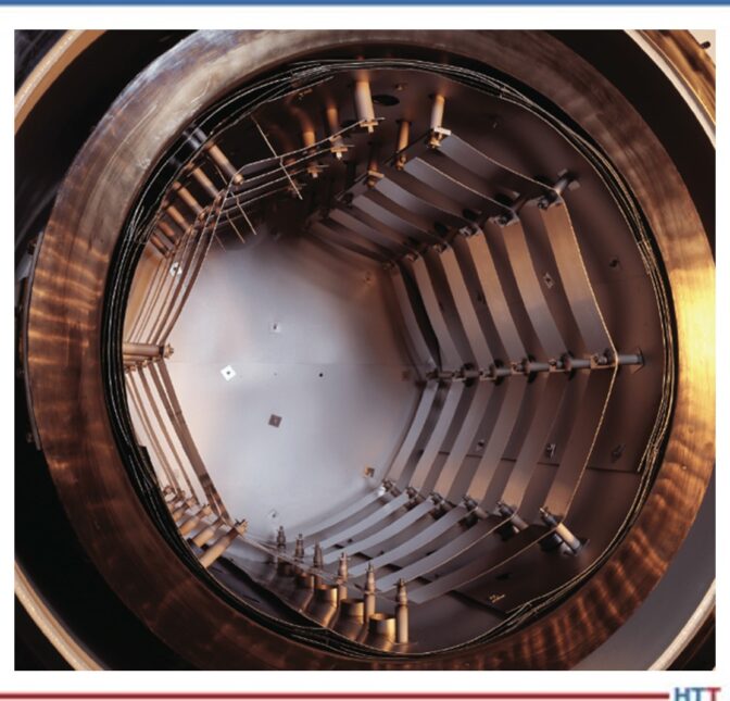
Vacuum Furnace Hot Zone Design
Image 2. Insulated
Source: Jason Schulze, Conrad Kacsik Instrument Systems, Inc.Image 3. Radiation
Source: Jason Schulze, Conrad Kacsik Instrument Systems, Inc.
The hot zone within a vacuum furnace is where the heating takes place. The hot zone is simply an insulated chamber that is suspended away from the inner cold wall. Vacuum itself is a good insulator so the space between the cold wall and hot zone ensures the flow of heat from the inside to the outside of the furnace can be reduced. There are two types of vacuum furnace hot zones used: insulated (Image 2) and radiation style (Image 3).
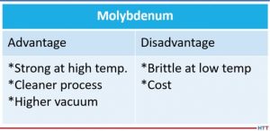
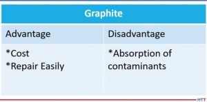
The two most common heat shielding materials are molybdenum and graphite. Both have advantages and disadvantages. Below is a comparison (Tables 1 and 2).
Table 1
Source: Jason Schulze, Conrad Kacsik Instrument Systems, Inc.Table 2
Source: Jason Schulze, Conrad Kacsik Instrument Systems, Inc.
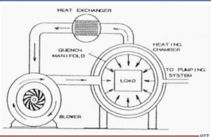
Vacuum Furnace Quenching System
Quenching is defined as the rapid cooling of a metal to obtain desired properties. Different alloys may require different quenching rates to achieve the properties required. Vacuum furnaces use inert gas to quench when quenching is required. As the gas passes over the load, it absorbs the heat which then exits the chamber and travels through quenching piping which cools the gas. The cooled gas is then drawn back into the chamber to repeat the process (see Figure 5).
Figure 5.Diagram of gas quenching
Source: Jason Schulze, Conrad Kacsik Instrument Systems, Inc.
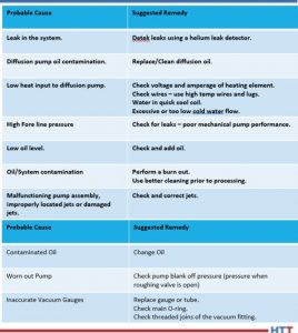
Vacuum Furnace Trouble Shooting
In Table 3 are some helpful suggestions with regard to problems processors may have.
Table 3
Source: Jason Schulze, Conrad Kacsik Instrument Systems, Inc.
Summary
Vacuum furnaces are an essential piece of equipment when materials need to be kept free of contamination. However, there are times when this equipment may not be necessary, and is therefore considered cost prohibitive, although this is something each processor must research. This article is meant to merely touch on vacuum technology and its uses. For additional and more in-depth information regarding vacuum furnaces, I recommend a technical book called Steel Heat Treatment, edited by George E. Totten.
About the Author: Jason Schulze is the director of technical services at Conrad Kacsik Instrument Systems, Inc. As a metallurgical engineer with over 20 years in aerospace, he assists potential and existing Nadcap suppliers in conformance as well as metallurgical consulting. He is contracted by eQuaLearn to teach multiple PRI courses, including pyrometry, RCCA, and Checklists Review for heat treat.
Heat treat specifications can be tiresome to stay up-to-date on. So it’s great when we find digestible content on AMS2750F to share with you.
In today’s best of the web article, you’ll be able to review the 4 new requirements for process instrumentation and what 18 pieces of information must always be reported in the calibration certificate.
An excerpt:
“The recording tools used on heat treatment plants should not be used to record TUS or SAT sensor temperatures unless it can be demonstrated that the recording channels of the TUS and/or SAT sensors of an integrated system are separated from the recording system of the heat treatment furnace and also meet the requirements of the field test instrument.”
Heat TreatToday publisher Doug Glenn wraps up this three-part series with Pelican Wire experts by talking with John Niggle from Pelican Wire about thermocouple insulation types and considerations.
The first two episodes cover the history, types, vocabulary, standards, and other basics of understanding how thermocouples work. Listen to the previous episodes of the series here.
Below, you can either listen to the podcast by clicking on the audio play button, or you can read an edited transcript.
The following transcript has been edited for your reading enjoyment.
Doug Glenn (DG): Welcome to Heat TreatRadio!
John Niggle (JN): Yes, it's good to see you again, Doug. I know we've run into each other a couple of times out there in the field. I'm looking forward to having the opportunity to do all of this stuff in person again.
DG: It will be nice. Before we hit the record button, we were talking about shows this fall and hoping that they happen because you, like I, are ready to get out and go.
You are the business development manager for Pelican Wire. If you don't mind, give us just a little bit of background about you and about your experience in the whole thermocouple world.
Pelican Wire headquarters
JN: Sure, absolutely. As you said, I am the business development manager at Pelican Wire. I've been at Pelican since 2013 so we're working out my eighth year here. I'm a career industrial sales representative. I do have previous experience also, actually, in the process instrumentation industry. Way back when, before I even knew how to spell thermocouples, I was selling that stuff when I first got out of college. My career has, sort of, gone full circle, let's say.
DG: Very nice. Well, you've got plenty of years of experience, which is great. We've had two previous episodes with your colleague, Ed Valykeo, and we covered a good bit of stuff. We covered a lot of basics in the first episode. We covered standardization, and things of that sort, in the second episode. I want to encourage any listeners who haven't listened to those episodes, feel free to go back, Google “Heat TreatRadio” and search for “Pelican Wire” and listen to episodes 1 and 2.
John, you and I want to move forward. I'm always kind of curious about this question: From your perspective, with your experience, why do we use thermocouples? Let's talk about what they are and why we use them.
JN: First of all, we have to assume that somebody is trying to measure the temperature of some sort of a process- a process or an event of some kind. That's basically what they're trying to do. Compared to other devices like RTDs, bimetal thermometers, liquid expansion state change devices and so forth, thermocouples are robust, they're inexpensive; they're repeatability, they're ease of use and size -- all of those factors lead them to be more widely used than another sort of thermal measurement device of any kind. It is the preferred method.
On top of that, I mentioned the expense part. Because they're relatively inexpensive, there are certain industries, the heat treat industry and smelting industry, for example, consider these as, actually, consumable or disposable. So, the cost factors in significantly in the industry that we're talking about here.
DG: I live in western Pennsylvania and the town where my wife grew up, there was an old Leeds and Northrup manufacturing plant. I believe they made the consumable thermocouples for melt shops. You would, basically, throw the thermocouple in and it would melt quickly but it would give you a response during that time.
CLICK to Listen!
JN: Right. And, as I mentioned earlier, the response factor is important, or that's one of the factors considered, when people are looking at thermocouple wire. And, you're correct, Ed Valykeo, as you mentioned, has 40 years of experience in the industry and has seen exactly the same sort of thing that you're talking about where people will just tack weld it onto something that gets thrown into a furnace or it gets thrown into a melting pot or something like that, and they're looking for that instantaneous temperature.
If you don't mind, I'll tell you that we've done some work, actually, in the aerospace industry and we had a customer that we sold significant, literally miles, of thermocouple wire to (when I say aerospace, it was specifically for space exploration) and this was because of whatever we had done with the insulation. I can't tell you, because it was before my time, but this is what was relayed to me- they were able to get another 3 - 4 seconds of temperature measurement out of that wire. That critical, extra data for them made all the difference in the world.
DG: We're going to get to the insulation part which should be interesting. You won't have to tell us any trade secrets, but we are headed in that direction anyhow.
So, different types of thermocouples. Again, just a review question for us. Why use them? Why the different types and why are we using different types?
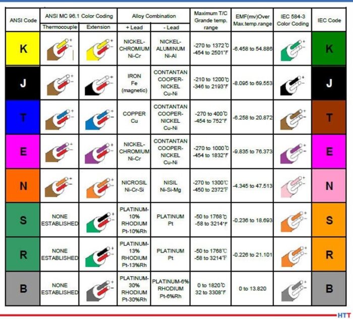
JN: Forgive me, Doug, and the rest of the audience, for that matter, if I end of repeating some of the things that came out in the previous episode. Basically, when you're talking about thermocouples, there are the two chemistries; for lack of a better term, you have “base” and “noble” metals. The base metals are really the metals that we focus on at Pelican. The noble metals are the more expensive ones- rare earth metals, tungsten, titanium, platinum and all those sorts of things that people spend exorbitant amounts of money on. There are purposes for those, but, typically, what you're going to see in the heat treat industry, in particular, you're going to see a lot of the base metals.
I like to say that, truly, the 20 gauge K, in particular, is the 800 pound gorilla in the room. It's almost considered, and I think it would be by people in the industry, a commodity. There are untold miles of that wire that are used in the heat treating and smelting industry. K is used, really, because of the temperature range. It fits in well with what people do in the heat treating industry. It is good for temperatures from zero up to around 1260 C. It's inexpensive, it covers the ranges that those people are looking for, and, again, it's the 800 pound gorilla in the room when it comes to temperature measurement in the heat treating industry.
Click to read the Heat Treat Today Original Content article on thermocouples.
The other types such as J comes up periodically, particularly if you're looking at lower temperature ranges. You won't see it quite as often in the heat treating industry. You will see it somewhat, but not to the degree that you would K. The J thermocouple wire has an iron leg so it does oxidize and you need to be careful about that sort of thing. Type T thermocouple wire has a narrower range. It has very good response times in cryogenic and cold temperature applications. The higher, upper end of type T thermocouple wire, typically, wouldn't be of terrible interest to the audience that we're involved with here, for the most part, because the upper ends around 370 to 400 C degrees, in lab environments; that's where it's going to be the most popular.
There is also type E. It's a higher temperature, as well. Response time. Broader range is a little bit better than K at lower temperature ranges. An interesting one is type N that you will see fairly often in the heat treating industry. For those people not familiar with type N, it is different alloys than type K. It covers virtually the same temperature range that type K does and will, actually, have less drift than type K. It is more expensive because of the alloys that it is made of, but, again, if you're interested in less drift, then type N is worth looking at. It hasn't quite caught on in the US the way it has in, say, Europe, in particular, and that really has to do with the infrastructure of the instrumentation. People have instrumentation that is either calibrated for K or J or something like that. Now, there is instrumentation out there, now, that would use K and N both, so we may see more, particularly, in the aerospace industry I would think it would become more and more popular.
DG: That's helpful. It's always good to hear those things over again.
How about the parameters and/or the factors that need to be considered when you're constructing the wire to start with? What do we need to be worried about in that area?
JN: I don't know if I like the word “worried” exactly, Doug. It's more, what do we need to think about? What do we need to be concerned about? Besides the metallurgy that we just talked about, we need to think in terms of what the sensor is actually going to look like. Is it just the wire? Thermocouple wire, by itself, can be a thermocouple; that's it, without any protection or anything like that.
As I mentioned earlier, you can tack weld it to an ingot, or something like that, and there you go. You don't have any probe, there is no thermal well to protect it or anything like that. But, what we do need to think about, then, is the process that it's going to be involved in. Where is it going to be used? Is it going to see an environment where there is a flow. Is it going to see an environment where somehow the thermocouple wire can become damaged? In that case, then, we're headed in the direction of talking about what our customers are interested in. And for a customer for Pelican Wire, we're mainly talking about people who actually assemble thermocouples – they make the connections, they have the molds and all that sort of thing.
To be clear, Pelican Wire just makes wire. And, again, the thermocouple wire can be used as a thermocouple, but a tremendous amount of wire is actually connected to some sort of a sensor or a probe, as I said, and is protected in a thermal well or something along those lines.
"But, what we do need to think about, then, is the process that it's going to be involved in. Where is it going to be used? Is it going to see an environment where there is a flow. Is it going to see an environment where somehow the thermocouple wire can become damaged? In that case, then, we're headed in the direction of talking about what our customers are interested in."
John Niggle
DG: Do we also have to be concerned with oxidizing, carburizing atmospheres, corrosive atmospheres? Is that, also, something that we need to be aware of?
JN: Absolutely. And that is one of the reasons you will see a probe thermocouple is because the wire is protected from that atmosphere. Nearly all of the wires that we talked about would be affected, particularly, in say, like a sulfurous environment; it would be subject to corrosion, oxidation and something along those lines.
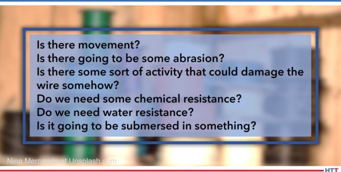
Other factors, of course, are the accuracy and how much space we have. Believe it or not, if it's going to go into a small orifice, then we need to think about what the age size is going to look like. And then the environment: Is it going to be abrasive? Is there movement? Is there some sort of braiding motion that could wear a hole in the wire in the insulation and so forth? There are a lot of things to think about.
DG: And, it would probably be a good idea, especially if our heat treat people are running anything outside of the norm, regardless of what it is, whether it be atmosphere, configuration, fixturing, if there is anything outside the norm, they would probably be wise to mention it to the thermocouple wire and/or thermocouple probe manufacturer and make sure that they know so that you guys can get help get the right thing on there in their furnace.
JN: Yes, absolutely. At the end of the day, we work with this every day. We have design engineers on staff who can assist with technical questions and so forth and, of course, our customers, and the actual thermal wire assembly people, this is what they do every day of the week.
“I'll tell you that we've done some work, actually, in the aerospace industry and we had a customer that we sold significant, literally miles, of thermocouple wire to (when I say aerospace, it was specifically for space exploration) and this was because of whatever we had done with the insulation.”
DG: Let's talk about something a little bit new, I guess, to our conversation here in this 3-part series, and that is the insulation that's going to go around these wires. Can you tell us what are the different types of insulations and what are the advantages and/or disadvantages of each, and why would we be using them?
JN: I'll break it down into, what I would call, the four basic categories. That would be an extruded insulation, insulations that are tapes, fiberglass insulations that are routinely worked with and then, of course, high temp textiles. High temp textiles, in particular, would be of interest to the audience here in the heat treat metallurgy world.
Extruded insulations can be a variety of thermoplastics. A term that, I think, Ed has probably mentioned before and we've talked about before is extension grade wire. That typically has a PVC insulation on it and the reason PVC works for that is that it's cheap and extension grade wire, typically, does not see the sorts of high temp environments that you're going to see in processes. It's really a signal wire that takes the signal from the probe or from the sensor to the process control device.
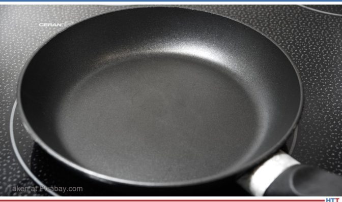
DG: So what kind of temperature tolerances can the extruded wire handle? Are we talking 300, 400 degrees? I guess you talk C, I talk F.
Teflon frying pan
JN: We talk whatever language our customer likes to talk, but we do talk C quite a bit. So, PVC is quite low, it's in the 200s F. But, when you're looking at fluoropolymer insulations (and Pelican is really a high temp house, so we focus on the higher temp insulations) you have FEP and PFA, those are in the 200s. PFA actually goes up to 260. So, you can see, it's probably not suitable for heat treating applications, smelting and that sort of thing. The advantages to those compounds would be that you're going to have abrasion resistance. Think about your Teflon frying pan: it's slick, it's smooth. So, if you're in an environment where there is some movement, it will be good for that. And, of course, it will have excellent moisture resistance and chemical resistance. Those would be the advantages to the extruded wire. The other advantage would be, because you'll have a thinner wall than you will with the other insulations, you'll have some more flexibility. So, if you have a type N radius, you can go around a corner easily.
The next step up, in terms of temperature resistance, would be the tapes. Basically, in that area, you're looking at PTFE tape, mica take and capped-on tape or polyamide tape. Those will give you slightly higher heat resistances. The mica, in particular, would give you more. (Mica, as a matter of fact, is used as a supplement to the PTFE to give it even higher heat resistance.) Mica will go up to 500 C, PTFE and the polyamides match, in terms of heat resistance, the extruder products around 260. What they do give you, again if you use the tapes, is the heat resistance you're looking for, some abrasion resistance and the moisture resistance. You'll have less flexibility because those products are stiffer, but they're also going to be a little bit lighter weight unless you incorporate the mica into it. Then, when you do that, you're going to end up with an even stiffer wire and it will be a little bit heavier, and all those will be larger in diameter than an extruded wire. If you look at an environment where you need to poke the wire through a hole and that hole is an eighth of an inch, you need to think really hard if what you're doing is going to work.
DG: So you've got extruded and you've got tapes.
JN: The next step after that would be fiberglass. In the case of fiberglass, you have E glass and S glass. Of the two, E glass would have the lower temperature resistance and you're looking at 482 C on the high end. For S glass, you're up to 704 C. Now you're starting to talk about insulations that you will see in the heat treat environment; it's quite common, especially on the S glass side where you're looking at the 704, you'll see a lot of people that need 500 C for whatever reason. The advantage, obviously, to the glass, as I mentioned, is the higher heat resistance.
There are disadvantages. Think about fiberglass for a minute. We actually have to saturate the wire to keep it from fraying without it ever really experiencing any abuse. If we don't saturate it, then the wire can fray, and you can get fiberglass in your fingers even, which is unpleasant. So, fiberglass has some disadvantages like that. If you put it in an environment where there is some movement, abrasion, vibration or something like that, it can be problematic. Also, it's going to be stiffer because it's saturated, typically. Sometimes you'll even see those saturants even cause problems in a heat treat environment where, if it gets too hot, the saturant can leave an ash behind. You're going to lose flexibility, as I said. You're not going to have the abrasion resistance, the chemical resistance or the moisture resistance that you're going to get from an extruded product.
The other one that we see, again, literally miles and miles and miles of, in the heat treat world would be what's called Refrosil and Nextel, (those are both, actually, trade names). We're talking about vitreous silica and ceramic. Again, those are, what we call, high temp textiles. Now, you're looking at products that are in the 1200 C range. Ceramic goes up to 1204, vitreous silica is in the 870's. Again, there are some of the same disadvantages with those that you're going to have with glass. It's going to be somewhat fragile. We don't saturate those because the saturants are not going to hold up in the environments that they're going to be placed into, so you would have that ash residue left.
Again, it will be stiff, it will be even larger in diameter than the fiberglass, which is larger than tape which is larger than the extruder products. Of course, you're not going to have the abrasion resistance, the moisture resistance or the chemical resistance. But it does protect the wire in those elevated temperature environments that are critical for the heat treating industry.
DG: Let's back up a bit. I want to understand something you said. You said, in the fiberglass, it is saturated and in the textiles it's not. I want to know what you mean by saturated.
JN: It's either a solvent-based or a water-based saturant that is applied to the wire to protect it. Think in terms of a varnish. It would be like a protective coating. Again, it just keeps the exterior of the wire, the bare wire, from being exposed. It's a coating, but we call it a saturant.
DG: High temperature textiles tend to be the stuff we're using, in the heat treat industry, probably most.
JN: Yes. Again, when I mentioned the 800 pound gorilla in the room, the 20-gauge K with the vitreous silica or the Refrosil would be an extremely popular product in the heat treating industry, absolutely.
DG: Let me ask you a very, very fundamental question. I'm curious of your answer to this. Why do we insulate wires at all? Is it done to protect from temperature or is it done simply to protect them from crossing with each other and grounding or shorting out? Why do we insulate?
"I'll go back to something that I know Ed talked about: the Seebeck effect. You have this loop; if you don't have that loop, then you don't have anything. You don't have the EMF, the electromotive force, that you're looking for."
John Niggle
JN: It is the second part. When you look at any wire construction, the two singles have to be insulated from each other. I'll go back to something that I know Ed talked about: the Seebeck effect. You have this loop; if you don't have that loop, then you don't have anything. You don't have the EMF, the electromotive force, that you're looking for. We do make a wire that is not duplex, but, typically, what you're going to see is a wire that has two singles and then it's duplexed with an insulation over the top. We do make a wire that the two singles are jacketed in parallel and then no jacket is placed over the top but that is for an application that wouldn't be suitable for the heat treat industry.
DG: I asked that question, because for those who are unbaptized in this conversation, it's kind of interesting. So, we're talking about insulation and we're doing a lot of conversation about temperature ranges and, for someone who wouldn't think so, they would say, "Well, that means you're insulating because of temperature." But, really, the reason you're insulating wire is for electrical. It's to keep them apart. It's just how high of temperatures those insulations can handle, not that you're insulating the wire to keep them cool. Right?
JN: Absolutely not.
DG: That may sound very basic, but there may be people that think that, so I want to get that on the table.
JN: Most of the people in the audience are probably familiar with this already. Typically, what happens is the wire is stripped so we have exposed ends. And then those ends, as we mentioned earlier, can be tack welded onto something or they can just be out there. The thermocouple world, by the way, is an incestuous world where we have customers, we kind of compete with those customers, some of our customers compete with others of our customers but then they buy supplies from each other. You probably already know that from talking with other people in this industry. At any rate, the wire is stripped and then it's either tack welded or it's connected to some sort of sensor or probe of some kind.
DG: It's a tangled web, the whole thermocouple world. You've got customers, yet you sell to certain suppliers who also sell to those customers. It can be complicated! But that's OK, we'll let you guys worry about that; we just want to make sure the thermocouples are good and we'll be in good shape.
Another question for you: We talked about the process and a lot of different environments about what type of thermocouple you should use, but does the process being monitored influence the type of insulation that should be used? Obviously, temperature is going to have an impact, but is there anything else?
JN: Yes. Let's circle back to what we talked about earlier just a little bit. When you look at the process, you need to think of what is going to happen to that wire? Is it going to see, first of all as you mentioned, the temperatures? That is certainly important so that comes into play with the insulation. But, we need to think about, Is there movement? Is there going to be some abrasion? Is there some sort of activity that could damage the wire somehow? Then, we need to look at the chemicals, like we talked about. Do we need some chemical resistance? Do we need water resistance? Is it going to be submersed in something? Those things all need to be considered.
Again, as I mentioned earlier, the actual placement of the wire. Does it need to be inserted in a hole? At Pelican, we produce wire down to 40 and actually 44 gauge which, I think, will probably be stunning to most of the people in your audience because, again, 20-gauge K is what these people think about. In the heat treating industry, what you see is they need a robust wire, something that's going to be able to handle those temperatures and a large conductor like that.
Another thing to think about, actually, is a bend radius. Are you going to put the wire somewhere where it needs to go around a corner, around a bend? Then, are you better off using a stranded wire? A stranded wire is going to have more flexibility. You can buy a 20-gauge stranded wire, you can buy 24-gauge, 28-gauge, 36-gauge.
DG: Now, what do you mean by stranded?
JN: Stranded wire would be instead of just one solid 20-gauge conductor, you have multiple strands that make up that 20-gauge. But, if you think about it, multiple strands of wire will actually be more flexible. You'll still get the same results, but it will be more flexible if you need to go around a corner or if you need to insert it into something.
DG: It's almost like a braided wire as opposed to a solid.
JN: Yes. Now braiding is a little bit of a different process. When we're talking about stranded wire, it's, basically, just spiral. Braided is more crossed into each other, which, coincidentally, is the way that the fiberglass and the high temp textile insulations are made – those are actually braided. And, by the way, I'll just toss this out, it's made on equipment that really hasn't changed since the ‘20s. I'm not talking about the 2020s, I'm talking about the 1920s! Rumor has it, some of that braiding equipment was, actually, designed by Thomas Edison. I'm not sure if that's really true. But that is the process used to apply the fiberglass and high temp textiles.
DG: So, anything else as far as any other considerations we need to take into consideration when we're talking about choosing insulation? If not, that's fine.
JN: I think I covered them, Doug.
DG: At Pelican Wire, your company, I know you guys deal with a broad number of markets, I'm sure, one of them being heat treat. What do you see as any special demands or special concerns that are, maybe, unique or, at least, inherent in the heat treat market?
". . . what you see is insulations that are higher in temperature resistance, as well. In some cases, as I mentioned earlier, in ovens where there is a saturant involved, we could see ash. Some people ask that saturant not be applied to the fiberglass and that's certainly something that can be done."
John Niggle
JN: For the heat treat market, again, I'll go back to what I said earlier, we see a lot of 20-gauge K used. It's because of the higher heat requirements, the higher heat that is involved with the processes of heat treating. Secondly, what you see is insulations that are higher in temperature resistance, as well. In some cases, as I mentioned earlier, in ovens where there is a saturant involved, we could see ash. Some people ask that saturant not be applied to the fiberglass and that's certainly something that can be done.
Sometimes we're even asked to not put tracers. We go back to what we talked about earlier with the metallurgy- you have two legs, a positive and a negative leg. Well, how do those end users tell those legs apart if they look similar, if they're an alloy of some kind? So, we put a tracer wire in there so you have a red leg and a yellow leg, in the case of type K, or sometimes you just have a red leg depending on what they ask for. Those tracers can, actually, cause problems, too, if the ovens are hot enough and they are in there for long enough times. We even have customers who ask us not to put tracers in their wire, for that matter.
Accuracy, of course, is extremely important. I know that Ed, in a previous episode, talked about standard limits, special limits and all that sort of thing. Typically, you're going to see special limits used in the heat treat industry and, in some cases, we're asked even for special calibration points. In previous podcasts, I've heard you talk with other people about AMS2750 and how that comes into play. It is extremely critical for the folks in the heat treating industry and something that clearly a thermocouple wire producer has to understand.
Episode 1 of 3 of AMS2750 series
DG: Let's say you've got a customer that calls you and wants to talk about their thermocouple needs, let's say there is some sort of special need. What would you suggest they have, in hand, when they call you? What do you need to know from them to help you do a better job with their thermocouple needs?
JN: Honestly, the first question we do ask is: What temperature are you going to be running this at? How hot are we going to be? We, absolutely, need to know that. That helps us narrow down the alloy that we might be looking at, whether it's type K, type J, type E, or whatever. And then, of course, it's a natural thing to dial in the insulation after that. Quite honestly, one of the things that frustrates me is when people say, "I need Teflon." Well, OK. Do you need FEP or do you need PFA? Those are both fluoropolymers like Teflon is. We need to talk about temperature resistance, so don't tell me you just need Teflon. We do need some specifics when it comes to that sort of thing. Again, we talked earlier about stranding and stranded wire. Do you need some flexibility? What gauge size do you think you need? How robust does this wire need to be? Those are some of the key factors we need to know about.
DG: Let's say, for example, somebody does want to get a hold of you or Ed, your colleague who was on the first two episodes, how is best to do that? How can we get a hold of Pelican Wire?
JN: Our web address is www.pelicanwire.com, about a simple as it possibly gets. Our email addresses are, actually, quite simple, as well. If anybody wants to email me, it's jniggle@pelicanwire.com. You can contact me directly, if you want to, or we have a sales inbox and that is simply sales@pelicanwire.com. We do have a phone number, but it seems a lot of people don't care about phone numbers as much these days. But the number is 239-597-8555.
DG: I have one, unrelated, question for you that I know the world is wanting to know: How is it having a company in Naples, Florida, that's what I want to know?
JN: I'll tell you what, Doug, the answer today will be different than the answer in October or December. It's actually quite nice. We moved down here 8 years ago in 2013. I moved from the Midwest and didn't really feature myself owning palm trees, but I own palm trees, which is pretty darn cool. We are, as the crow flies, about 3 miles from the water, where I live anyhow, 20 minutes by car. Our office and manufacturing facility are, actually, on the very edge of the everglades. You can see the picture in the background behind me. That's our building. That's actually facing east. That is a sunrise over the everglades. We're on the very edge of the everglades. There is a lake right next to our building and then, after that, it's everglades all the way over to Miami. And, real quick, our weather pattern comes from the east. It doesn't come from the Gulf. This time of year, in the summer at about 3:00 in the afternoon, about the time that we're doing this call right now, a thunderstorm blows up and it comes from the east over the everglades and it moves to the west. The trees blow that direction, you can see it coming. It's interesting. During the wintertime, I have to tell everyone, you'd probably be jealous, but it is truly paradise.
DG: Yes! I've been to Naples, ate at a nice restaurant down there, years ago, but it was very nice.
You guys are also employee-owned, right?
JN: That's correct, yes. The company is over 50 years old. The founder of the company passed away in 2008 and, before he passed away, he converted the company to an employee-owned operation. So, we've been employee-owned since 2008. We've purchased a couple other companies since then that folded into, what we call, the Wire Experts Group. Pelican Wire is part of that. We have a sister company out in Colorado. We bought another facility in Chicago and folded that into our company in Colorado. So, yes, we're employee-owned and it works out really well for the employee owners, I'll tell you that much.
DG: That's great. John, it's been a pleasure talking with you. Thanks for taking the time. I appreciate your expertise. Hopefully, we will see you out on the pavement somewhere in the real world.
JN: I'll, actually, be seeing you at the heat treat show in about 3 weeks.
DG: That's about right, yes.
JN: Hopefully, some of the people that are listening we will see, as well.
Doug Glenn
Publisher Heat TreatToday
To find other Heat Treat Radio episodes, go to www.heattreattoday.com/radio and look in the list of Heat Treat Radio episodes listed.