What process holds a soft spot in your heart? Tempering or annealing? For Valentine's Day, turn up the heat -- errr heat treatments -- with this look at the differences in tempering and annealing! Heat TreatToday has resources for you to spark some thought and learning on these processes.
Sentiments and strong feelings can certainly be heightened this Valentine's Day. While tempering and annealing may not lend themselves easily to the holiday, we hope you enjoy a bit of a nod to the day in our headings below. Make use of the Reader Feedback button, too, and keep us in the loop with questions and comments on what heat treatment you love.
Problem with Annealing? Get to the Heart of the Issue
An automotive parts manufacturer was running into problems with cracking parts. The variable valve timing plates were returning from heat treatment with this problem. To determine why those parts were cracking after the annealing process, an investigation was launched by metallurgists at Paulo.
The presence of nitrogen combining with the aluminum already present in the particular steel being used was forming aluminum nitrides. What could be done? Read more in the case study article below to find out a workable solution that allowed the annealing to create a crack-free product.
Induction, Rapid Air, Oven and Furnace Tempering: Which One do You Love?
Contact us with your Reader Feedback!
This article gives some perspectives, from experts in the field, on what kinds of tempering are available and for what the processes are used.
Hear from Bill Stuehr of Induction Tooling, Mike Zaharof of Inductoheat, and Mike Grande of Wisconsin Oven with some basics and background information on tempering. Those reasons alone make this resource helpful with information like this: "tempering at higher temperatures results in lower hardness and increased ductility," says Mike Grande, vice president of sales at Wisconsin Oven. "Tempering at lower temperatures provides a harder steel that is less ductile."
More specific in-depth study is presented as well. The Larson-Miller equation is considered, and the importance of temperature uniformity is emphasized. Read more of the perspectives: "Tempering: 4 Perspectives — Which makes sense for you?"
Cast or Wrought Radiant Tubes in Annealing Furnaces - is Cheaper Really What to Fall For?
Marc Glasser, director of Metallurgical Services at Rolled Alloys, takes a look at radiant tubes. He particularly discusses the cast tubes and wrought tubes. For use in continuous annealing furnaces, there are several factors contributing to choice of radiant tube type.
Marc says, "Justification for the higher cost wrought alloy needs to take into consideration initial fabricated tube cost, actual tube life, AND the lost production of each anticipated downtime cycle as these downtime costs are often much more than material costs." He probes into areas that may not be considered when thinking of all the costs involved. Read more of his article "Radiant Tubes: Exploring Your Options."
Tempering Furnaces: Improvements are Thrilling
The expert behind this piece shows the importance of tempering, particularly in automotive fastener production. Tim Donofrio, vice president of sales at CAN-ENG Furnaces International Limited examines what's working in the tempering furnaces. The products are meeting and exceeding expectations.
To wrap up this Technical Tuesday post on tempering and annealing, head over to this additional resource to round out the scope of each process. "What is the Difference: Tempering VS. Annealing" gives a summary perspective on the heat treatments discussed above.
Find heat treating products and services when you search on Heat Treat Buyers Guide.com
There are many radiant tube options on the market, so which one is best for your furnace and your budget? In this column that compares radiant tubes in carburizing and continuous annealing furnaces, discover how two major types of radiant tubes stack up.
Marc Glasser, director of Metallurgical Services at Rolled Alloys, investigates more deeply the two choices. This Technical Tuesday discussion on radiant tubes options will be published inHeat Treat Today'sFebruary 2023 Air & Atmosphere Heat Treating Systems digital edition.
Introduction
Marc Glasser Director of Metallurgical Services Rolled Alloys Source: Rolled Alloys
Radiant tubes are used in many types of heat treating furnaces from carburizing furnaces to continuous annealing of steel strip. Generally, a heat treater has three options for radiant tubes: cast tubes, wrought tubes, and ceramic silicon carbide tubes. Silicon carbide tubes are rarely used by heat treaters, so this article will not delve too deeply into this option. Suffice it to say, ceramic materials can often handle much higher temperatures at the expense of ductility; ceramics are more brittle than metals, making them prone to failure from the small impacts, so metal cages are sometimes fabricated to protect them. Most of the tubes being used today are cast radiant tubes. With new casting technology — primarily centrifugal casting — thinner tubes are being cast at a lower cost, which then results in a shorter life.
The primary factors for choosing radiant tube material are tube temperature and carbon potential of the furnace atmosphere. Cost-benefit analysis should also be considered. There are multiple applications for radiant tubes, including carburizing furnaces, continuous annealing furnaces for steel sheet galvanizing, steel reheat furnaces, and aluminum heat treating. This article will explore two of the aforementioned radiant tube options, specifically for carburizing and continuous annealing furnaces.
Radiant Tubes for Carburizing Furnaces
Gas carburization is traditionally performed between 1650°F and 1700°F at a carbon potential of 0.8% approximating the eutectoid composition. In today’s competitive environment, more heat treaters are increasing temperatures to 1750°F and pushing carbon potentials as high as 1.6% to get faster diffusion of carbon while spending less time at temperature. INCONEL® HX (66% Ni, 17% Cr) has been a common cast alloy seen in carburizing furnaces. This alloy is regularly selected for its resistance to oxidation and carburization up to 2100°F. Super 22H is more heavily alloyed than HX and is seeing more use as carbon potentials increase but at a premium price. With advances in centrifugal castings, cast tube wall thicknesses have decreased from 3/8-inch to 1/4-inch. Some heat treaters have shared that this decrease in wall thickness has also led to shorter tube life.
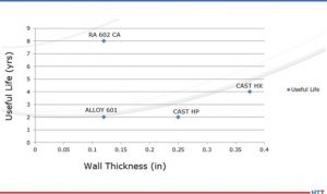
Fabricated and welded radiant tubes in alloys 601 and RA 602 CA® have been tested in industry. When tested, these wrought alloys were fabricated to have a wall thickness of 1/8-inch. At the extremes, tubes fabricated from 601 only lasted 50% as long as cast HX. Historically, HX tubes have been approximately 33% higher in cost than that of 601 and utilize heavier 3/8-inch walls. A little-known fact is that by switching to a thinner wall cast tube, the life drops by 50%. By switching to 1/8-inch wall thickness, RA 602 CA tube life has been extended to eight years or more, while running at 1750°F and up to 1.6% carbon potential, at just a 33% premium over cast HX. Life cycle data are presented in Figure 1.
Figure 1. These life cycle comparisons were done in carburizing furnaces only. In non-carburizing furnaces, justification of alloy selection is dependent on actual operating conditions and each individual operator’s own experience. Source: Rolled Alloys
Radiant Tubes for Continuous Annealing Furnaces
In the area of continuous annealing, the cast alloy of choice is HP/HT (35% Ni, 17% Cr, 1.7% Si, 0.5% C). Here again, this casting has been compared to 601 and RA 602 CA, with the same results. The total life data from these trials are also incorporated into Figure 1. During the collection of this data, there has been no effort to measure the actual tube temperature, so the effect of tube temperature is not clearly defined. In these continuous annealing furnaces, it has been reported that the tubes at the entry end are subject to more heat absorption as burners are firing more due to the continuous introduction of cold material; in trials, the operators have not kept adequate documentation of specific tubes, making justification more diffcult.
Justification for the higher cost wrought alloy needs to take into consideration initial fabricated tube cost, actual tube life, AND the lost production of each anticipated downtime cycle as these downtime costs are often much more than material costs. Only individual fabricators can determine these costs.
The Economics
Table 1 Source: Rolled Alloys
Table 1 above shows the economics of metal alloy choice. To properly interpret, understand that the costs are not actual, but rather relative to 601, so a round number of 1000 was used. With a 30% greater cost of cast tubes, that translates to a relative cost of $1300. The annual cost is the amortized cost over the life of the tube. The total eight-year cost is the relative cost times the number of tubes that would have to be purchased to obtain the life cycle of one tube of the longest-lasting material over its full life cycle.
Missing in this analysis is the additional cost of downtime and lost production. For the replacement of radiant tubes in a carburizing furnace, this typically entails a full week to turn a furnace off, allow it to cool, replace the tubes, and then heat it up again. Many heat treaters do not consider this, and therefore it is a hidden cost. Even without the downtime being considered, by examining the total cost of materials (including replacements) compared to the longest-lasting tube, it turns out that the most expensive tube is the cheapest tube. The obstacle to overcome is whether the heat treater is willing to wait eight years to realize these cost savings.
There can be additional factors to consider. With improvements in the efficiency of casting, the actual costs of the thinner wall casting may be somewhat less, but to match the overall cost of the longest-life material, it would have to be less than half the expected cost. As better, more expensive cast alloys become accepted and actual life data becomes available, these more costly alloys can be added to this table for comparative analysis, too.
This same method of analysis can be applied to radiant tubes for continuous annealing furnaces, but more details will need to be added including furnace position. Different alloy candidates will have to be put to the test in actual operations, carefully document what alloy is in what position or location, and when it gets changed out. This becomes quite cumbersome when annealing furnaces (depending on design and manufacture) can have over 200 radiant tubes.
Conclusion
Currently, cast alloy tubes dominate the market. The concept of total life cycle cost has been introduced as a means of more accurately justifying one’s choice of radiant tube. This comes into play more as processes are pushed beyond traditional process conditions. Cost-benefit analysis must be balanced over acceptable amortization time, of course. However, performing the full analysis as well as the costs saved from downtime may lead some heat treaters to some alternate materials.
About the author: Marc Glasser is the director of Metallurgical Services at Rolled Alloys and is an expert in process metallurgy, heat treatment, materials of construction, and materials science and testing. Marc received his bachelor’s degree in materials engineering from Rensselaer Polytechnic Institute and a master’s degree in material science from Polytechnic University, now known as the NYU School of Engineering. Contact Marc at mglasser@rolledalloys.com
Find heat treating products and services when you search on Heat Treat Buyers Guide.com
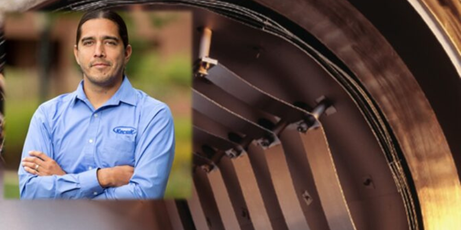
Vacuum furnaces are widely used in the aerospace and automotive industries. These furnaces are used for multiple processes including brazing, aging, and solution heat treating for countless materials. Typically, vacuum furnaces are utilized to ensure a lack of oxidation/contamination during heat treatment. This article will talk about the origins, theory, and main parts of vacuum technology and how it is used in both aerospace and automotive industries.
This Technical Tuesday feature was written by Jason Schulze, director of technical services at Conrad Kacsik Instrument Systems, Inc., and was first published in Heat Treat Today's December 2022 print edition.
A Brief History
Vacuum furnaces began to be used in the 1930s for annealing and melting titanium sponge materials. Early vacuum furnaces were hot wall vacuum furnaces, not cold wall vacuum furnaces like we use today. Additionally, most early vacuum furnaces did not utilize diffusion pumps.
Vacuum Heat Treat Theory
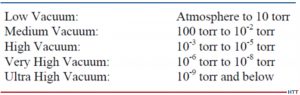
Vacuum technology includes vacuum pumping systems which enable the vessel to be pulled down to different stages through the process. Degrees of vacuum level are expressed opposite of pressure levels: high vacuum means low pressure. In common usage, the levels shown below in Figure 1 correspond to the recommendations of the American Vacuum Society Standards Committee.
Vacuum level will modify vapor pressure in a given material. The vapor pressure of a material is that pressure exerted at a given temperature when a material is in equilibrium with its own vapor. Vapor pressure is a function of both the material and the temperature. Chromium, at 760 torr, has a vapor pressure of ~4,031°F. At 10¯5, the vapor pressure is ~2,201°F. This may cause potential process challenges when processing certain materials in the furnace. As an example, consider a 4-point temperature uniformity survey processed at 1000°F, 1500°F, 1800°F, and 2250°F. This type of TUS will typically take 6-8 hours and, as the furnace heats up through the test temperatures, vacuum readings will most likely increase to a greater vacuum level. If expendable Type K thermocouples are used, there is a fair chance that, at high readings, you may begin to have test thermocouple failure due to vapor pressure.
Figure 1. Vacuum levels corresponding to the recommendations of the American Vacuum Society Standards Committee
Source: Jason Schulze, Conrad Kacsik Instrument Systems, Inc.
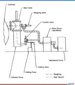
Vacuum Furnace Pumping System
Vacuum heat treating is designed to eliminate contact between the product being heat treated and oxidizing elements. This is achieved through the elimination of an atmosphere as the vacuum pumps engage and pulls a vacuum on the vessel. Vacuum furnaces have several stages to the pumping system that must work in sequence to achieve the desired vacuum level. In this section we will examine those states as well as potential troubleshooting methods to identify when one or more of those stages contributes to failure in the system.
Vacuum furnaces have several stages to the pumping system that must work in sequence to achieve the desired vacuum level. Each pump within the system has the capability to pull different vacuum levels. These pumps work in conjunction with each other (see Figure 2).
Figure 2. Vacuum pumps work in conjunction with one another
Source: Jason Schulze, Conrad Kacsik Instrument Systems, Inc.
The mechanical pump is the initial stage of vacuum. This pump may pull from 105 to 10. At pressures below 20 torr the efficiency of a mechanical pump begins to decline. This is when the booster pump is initiated.
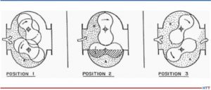
The booster pump has two double-lobe impellers mounted on parallel shafts which rotate in opposite directions (see Figure 3).
Figure 3. Booster pump positions
Source: Jason Schulze, Conrad Kacsik Instrument Systems, Inc.
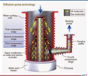
The diffusion pump (Figure 4) is activated into the pumping system between 10 and 1 microns. The diffusion pump allows the system to pump down to high vacuum and lower. The diffusion pump has no moving parts.
Figure 4. Diffusion Pump
Source: Jason Schulze, Conrad Kacsik Instrument Systems, Inc.
The pump works based on the vaporization of the oil, condensation as it falls, and the trapping and extraction of gas molecules through the pumping system.
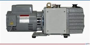
Image 1. Holding Pump
Source: Jason Schulze, Conrad Kacsik Instrument Systems, Inc.
The holding pump (Image 1) creates greater pressure within the fore-line to ensure that, when the crossover valve between the mechanical and diffusion pump is activated, the oil within the diffusion pump will not escape into the vessel.
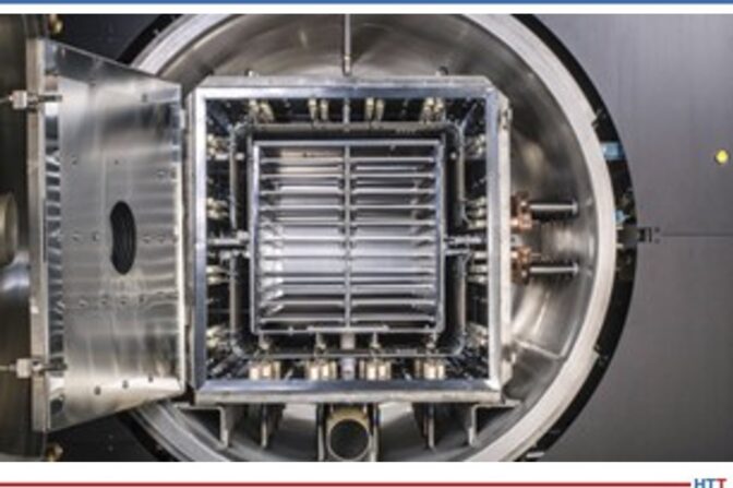
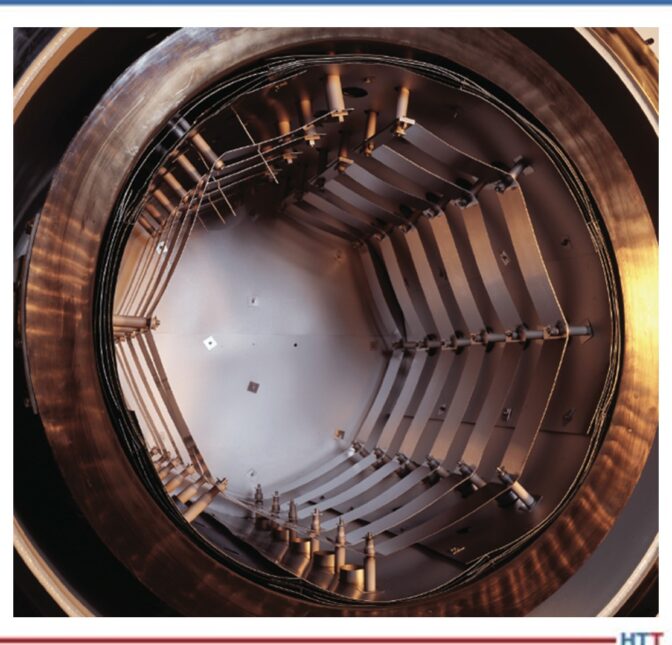
Vacuum Furnace Hot Zone Design
Image 2. Insulated
Source: Jason Schulze, Conrad Kacsik Instrument Systems, Inc.Image 3. Radiation
Source: Jason Schulze, Conrad Kacsik Instrument Systems, Inc.
The hot zone within a vacuum furnace is where the heating takes place. The hot zone is simply an insulated chamber that is suspended away from the inner cold wall. Vacuum itself is a good insulator so the space between the cold wall and hot zone ensures the flow of heat from the inside to the outside of the furnace can be reduced. There are two types of vacuum furnace hot zones used: insulated (Image 2) and radiation style (Image 3).
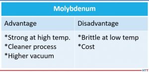
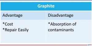
The two most common heat shielding materials are molybdenum and graphite. Both have advantages and disadvantages. Below is a comparison (Tables 1 and 2).
Table 1
Source: Jason Schulze, Conrad Kacsik Instrument Systems, Inc.Table 2
Source: Jason Schulze, Conrad Kacsik Instrument Systems, Inc.
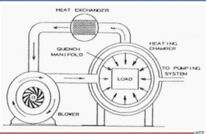
Vacuum Furnace Quenching System
Quenching is defined as the rapid cooling of a metal to obtain desired properties. Different alloys may require different quenching rates to achieve the properties required. Vacuum furnaces use inert gas to quench when quenching is required. As the gas passes over the load, it absorbs the heat which then exits the chamber and travels through quenching piping which cools the gas. The cooled gas is then drawn back into the chamber to repeat the process (see Figure 5).
Figure 5.Diagram of gas quenching
Source: Jason Schulze, Conrad Kacsik Instrument Systems, Inc.
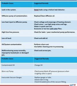
Vacuum Furnace Trouble Shooting
In Table 3 are some helpful suggestions with regard to problems processors may have.
Table 3
Source: Jason Schulze, Conrad Kacsik Instrument Systems, Inc.
Summary
Vacuum furnaces are an essential piece of equipment when materials need to be kept free of contamination. However, there are times when this equipment may not be necessary, and is therefore considered cost prohibitive, although this is something each processor must research. This article is meant to merely touch on vacuum technology and its uses. For additional and more in-depth information regarding vacuum furnaces, I recommend a technical book called Steel Heat Treatment, edited by George E. Totten.
About the Author: Jason Schulze is the director of technical services at Conrad Kacsik Instrument Systems, Inc. As a metallurgical engineer with over 20 years in aerospace, he assists potential and existing Nadcap suppliers in conformance as well as metallurgical consulting. He is contracted by eQuaLearn to teach multiple PRI courses, including pyrometry, RCCA, and Checklists Review for heat treat.
Additive manufacturing (AM) at a commercial scale began about 30 years ago and has expanded well beyond its original scope. As AM becomes increasingly prominent across different industries, heat treaters need to know how to handle AM parts in their shops. Learn about the history of binder jetting AM, the alloys used in this technology that require heat treatment, and what heat treaters should expect for the future.
Read why Animesh Bose of Desktop Metal thinks that binder jetting AM is only going to be used more and more in several heat treating sectors.
This article first appeared in Heat Treat Today’s December 2022 Annual Medical and Energy print edition.
Binder Jetting of Metals: Origins
Animesh Bose Vice President of Research & Development Desktop Metal Source: LinkedIn
Additive manufacturing (AM) at a commercial scale began about 30 years ago and has expanded well beyond its original scope. At the beginning, rapid prototyping (RP) was the name for the burgeoning technology; it emerged in the 1990s to bridge the gap between the need for quickly produced prototypes for manufacturers, not just plastic replicas. Rapid tooling (RT) of metal tooling parts joined RP R&D at this time as the research frontier for materials engineers. The current name for these technologies stands at “additive manufacturing,” or AM, though the popular terminology is simply “3D printing.”
Polymers
Developments in polymer AM also advanced rapidly with both extrusion-based technology as well as through advancements in Digital Light Processing of photopolymers. Stratasys Ltd., an American-Israeli manufacturer of 3D printers, software, and materials for polymer additive manufacturing as well as 3D-printed parts on-demand, began using a material extrusion-based process with their FFF (fused filament fabrication) technology to print parts, patented in 1989. This worked by feeding coils of polymeric materials though a printer, which would extrude the material through a small, heated chamber where the material would pass through a small orifice to extrude – or print – in a three dimensional design. This method allowed for very fine, hair-like material to print in a precise X ,Y, and Z motion, building layer by layer. Vat polymerization was another polymer AM technology that gained traction and involved photopolymer processing. Both technologies are currently used for polymeric materials. Interestingly, both processes have been adapted and are being used for metal 3D printing.
Metal AM
In 1993, an MIT engineering professor named Emanuel “Ely” M. Sachs – a man who could be considered the father of metal binder jetting technique – along with his colleagues from MIT patented the process of laying fluent, porous materials in layers between 50- to 100-micron thickness to form 3D parts. They were able to do this by spraying an organic binder on each layer of material where they wanted to increase the height of the part to produce a bonded layer in the selected area. This layering is repeated several times before the unbonded powder is removed immediately or after further processing.
One of the biggest advancements in metal AM happened in 2014 when GE Aviation combined multiple parts into one huge, complex design using a laser-based additive manufacturing method called direct metal laser melting. The end result was an airplane fuel nozzle made of 20 parts for the LEAP™ engine. All of AM came into the limelight, and direct metal laser melting – a melt-based technology – just took off.
But there were limitations to this laser process, the main one being cost and special powder requirements to layer and melt to form the part. The process was also technologically intensive and not fast enough for high volume production (as would be necessary for automotive or consumer good-type application).
Binder Jetting Technology
Binder jetting that had been developing in the early 2000s started to gain traction as a non-melt-based process for high volume mass production. Instead of melting the powder material, a binder is used to adhere the powder metal layers where needed. This method of printing results in a more uniform final part microstructure compared to the melt-based processes. ExOne, a binder jet 3D printing company, pursued the binder jetting technology using a license from MIT. In 2015, Desktop Metal was formed, and they focused on high volume mass production by binder jet using their Single Pass Jetting (SPJ™) technology. As binder jet gained traction, other companies entered the market (HP, GE, and Digital Metal). Desktop Metal recently acquired ExOne and efforts at developing standards for the technology are in full swing.
Heat Treating of AM Metals
Stainless Steels
There are two popular types of stainless steel for AM. The first is 17-4 PH, a precipitation-hardened stainless steel, which I like to call an “all purpose” stainless steel. When heat treated, one can achieve varying levels of strength, hardness, and elongation; and since it’s stainless steel it has a reasonable corrosion resistance. The aging treatments are already well-established – for example, H900, H1100, etc. The other popular grade is 316L, a non-heat treatable grade used in the food industry among others. Now, most stainless steels have chromium and nickel in decent amounts, so companies have developed a grade which is called “nickel-free stainless steel” for applications where people might be allergic to nickel. This class of alloy is also heat treatable. There are many more stainless steel grades that are being developed by the binder jet process.
Low Alloy Steels
Many low alloy steels are used in AM. For example, 4140 and 4340 have various, small amounts of alloying elements. These low alloy steels also need to be heat treated.
Tool Steels
Again, most tool steels are heat treatable. One of the most popular grades is H13; it is a tool steel that is heat treatable and can achieve fairly high hardness. It’s used for dies and other types of tooling.
Then, there is a category of tool steels known as A2 and D2; those are steels in which the strength can be changed through heat treatment.
Metal Alloys with Binder Jetting
There are also non-steel alloys that are used in binder jetting and require heat treatment. One example is nickel-based alloys, which fall in the broad category of super alloys. With some of these alloys, a heat treater would solutionize the part by taking it to a high temperature (950-1000°C), hold it for 60 minutes, and then quench in water, high pressure gas, or (in some instances) in air. The part then undergoes an aging treatment for several hours, depending on part thickness.
Additionally, there is a class of copper alloys with small amounts of zirconium and chromium that is heat treatable. These alloys have lower thermal and electrical conductivity compared to pure copper but have an advantage of higher strength and hardness over pure copper, which is very soft and malleable. For example, in applications that require additional strength and hardness compared to copper, the copper zirconium-chromium-based alloys may be appropriate since their strength and hardness can be increased by heat treatment.
This is just an introduction to the many alloys that have been used in binder jetting that need heat treatment.
Future of Binder Jet and Heat Treat
While heat treaters know about AM in the medical and aerospace industries, AM will likely gain more traction in the automotive industry. Presently, these are relatively small parts, but you will begin to see larger components coming from AM; one of the things to be aware of is that AM can create organic shapes, including all kinds of twisted and complex metal geometries. To ensure that these organic shapes do not distort or droop, larger parts must be well-supported. The development of a software known as Live Sinter™ by Desktop Metal offers the possibility of negatively distorting a complex shaped part (in the green state) so that after sintering, the part shrinks and distorts to eventually provide the desired complex shape at the end. This allows for the possibility of sintering parts either with minimal or without any support structures.
Heat treaters can also anticipate high volume AM production. This is one of the major focuses for binder jet engineers – to reduce costs for most automotive parts – as it will make AM very appealing to this cost-conscious industry.
Finally, optimizing sintering processes and related equipment for AM parts will result in meeting the production demands of the industry, and this will lead to AM parts being seen in heat treat shops more regularly. It would not be a stretch to consider (since there are heat treatments where gas atmosphere quenching at high pressures is possible), that the complete heat treatment cycle may be performed in the same furnace.
About the Author: Animesh Bose is the vice president of Research & Development at Desktop Metal, where he is responsible for building out the company’s palette of materials that can be used to print quality parts. He has been involved in the area of powder metallurgy and particulate materials (PM) for more than thirty years.
Heat treating solutions are important for more than keeping an airplane flying in the sky or a bridge suspended above the water. These two examples are high profile, but what about the heat treating solutions that do not zoom through the air or mark the skyline above rivers? In the medical industry, heat treating solutions are often unseen unless something goes wrong.
When it comes to medical implant and device heat treating, what options are available to manufacturers that will benefit patients? What should we know about the heat treating processes that make metal parts functional as knees, hips, and elbows? Find out in this expert analysis from Quintus Technologies and ECM USA, Inc.
This Technical Tuesday article was first published in Heat Treat Today's December 2022 Medical and Energy print edition.
Introduction
Dan McCurdy, former president at Bodycote, Automotive and General Industrial Heat Treatment for North America and Asia, knows full well just how much time, energy, and pain the right medical heat treating practice and alloy composition can save a patient. Dan’s wife suffered from complications due to a nickel allergy in a traditionally thermally-processed ASTM F75 knee implant. She dealt with constant inflammation, swelling, and pain. Physical therapy and a second procedure did nothing to ease the discomfort. The best medicine for Dan’s wife? A specially heat treated medical implant (more of Dan's story can be found at the end of this article).
Contact us with your Reader Feedback!
To understand the stories behind final medical products, Heat Treat Today asked Quintus Technologies and ECM USA, Inc. to share two different approaches on medical implant and device heat treatment. These two companies at the forefront of the medical heat treating industry shared about hot isostatic pressing (HIP) with additive manufacturing, and vacuum heat treating. Read their answers to our questions and learn how, when it comes to implantable medical devices, heat treating can be the best medicine.
How do you ensure your equipment maintains the precise specifications required in the medical industry? What specifically is necessary to maintain compliance when it comes to medical implants?
Quintus Technologies
Chad Beamer Applications Engineer Quintus Technologies
Quintus Technologies has observed a trend in bringing Nadcap to the medical industry. Historically the medical industry has focused on the standards and regulations for the quality management system of their approved supplier, but a consistent transition to technical aspects of critical processes (including HIPing) is becoming the norm. Quintus Technologies’ background is one of delivering HIP equipment in line with Nadcap and AMS2750 specifications. The medical industry requires best-in-class temperature uniformity and accuracy; systems designed with production driven flexibility (such as thermocouple quick-connectors for T/C sensor installation
to minimize downtime); HIP furnaces equipped with uniform rapid cooling (URC®) for optimized cycle productivity; active involvement in standards committees; and working directly with the industry.
Requirements are increasing in terms of productivity and the introduction of more complex surface requirements. It is crucial to work closely with the industry to reduce oxidation of orthopedic implants during the HIP and heat treatment processes.
Steering of the HIP cycle is key, along with in-HIP heat treatments to achieve the desired microstructure for the application, which is a standard offering for High Pressure Heat Treatment™ (HPHT™) equipment.
ECM USA, Inc.
Dennis Beauchesne General Manager ECM USA, Inc.
Some of the features that are most important are leak rate at deep vacuum along with a chamber and furnace design that does not contribute to any contamination. In our systems, these features, along with others, are of the utmost importance when supplying equipment for the medical implant market.
What are the top 3–5 key requirements or compliance/quality issues needed to heat treat medical implants?
Quintus Technologies
There are several industry standards that have been released to establish key requirements for the HIP process that are often leveraged for medical applications demanding performance and reliability. For example, Nadcap has released AC 7102/6 which details the audit criteria for HIP. This document was developed with significant input from the industry and the government to define operational requirements for quality assurance. It offers a checklist for the HIP processing of metal products and includes requirements for:
managing the equipment per pyrometry standard AMS2750
qualifying technical instructions and personnel training
handling product during the loading and unloading operations
complying with gas purity requirements of the pressure medium
controlling temperature, including uniformity and accuracy evaluations and management
These aspects are critical to ensure product quality meeting medical customer requirements and expectations. Recent additions beyond conventional requirements highlighted above include high speed cooling in the HIP process (>200 K/min) for some materials which is important for metallurgical results.
ECM USA, Inc.
Key requirements include thermal performance (both uniformity and ramp control); real-time vacuum and gas management; traceability and production lot follow up through human machine interface (HMI); quality procedures for all sensor calibrations; and remote access for control and troubleshooting.
Can you share an example of how your equipment could be used to heat treat a medical implant/device from start to finish?
Quintus Technologies
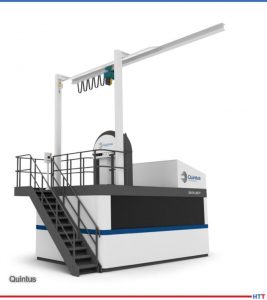
Many medical implants — whether fabricated using conventional processing techniques such as casting, or more novel approaches such as additive manufacturing — require HIP to eliminate process related material defects. Defects include shrinkage porosity for castings and lack-of-fusion and keyhole defects for fusion based additive manufacturing techniques. These defects can have a negative impact on product quality, impacting performance and reliability. Once HIP has been applied to a material, post processing is often not complete, with additional thermal treatments required to achieve the optimum microstructure leading to the desired material properties and performance. Such thermal treatments are material and process dependent, but could include a stress relief, solution anneal, rapid cooling or quenching, and aging and are often applied in separate heat treat equipment.
Hot Isostatic Press QIH 60 offering our most advanced Uniform Rapid Cooling (URC®) furnace technology with industry leading temperature control and accuracy
Quintus Technologies has introduced HIP systems providing capabilities beyond conventional densification. Decades’ worth of work in equipment design, system functionality, and control now offers an opportunity to perform HIP and heat treatment in a combined cycle, referred to as HPHT. Combined HIP and heat treatment for castings and AM implants can mitigate the risk of thermally induced porosity, as well as grain growth, which can offer advantages for mechanical and chemical properties in implants. This methodology provides a more sustainable processing route with improved productivity and energy efficiency. A joint HIP and heat treatment offers significant advantages with lead time, and this improvement in lead time couples well with the demands placed on the personalized medical implants. It also offers opportunities to further optimize microstructures for improvement in material properties coupled with ease of manufacturability. HPHT and modern HIP equipment may allow for a higher performing material system, which produces an implant with improved reliability and life.
Within the medical industry, fine grain AM microstructure, repeatability, and low porosity are key concerns. There are many reported benefits by applying the combined HPHT route such as reduced number of process steps, reduced cycle time and lead time, and improved process and quality control. Other advantages include spending less time at elevated temperatures helping to preserve the fine grain AM microstructure by minimizing grain growth. Tight control and steering of the cooling rates during the different steps of the HPHT cycle ensures repeatability of the properties. Manufacturability can be improved through HPHT as this approach reduces the cooling or quench severity during cooling segments which can often lead to part distortion or cracking. Improved functionality and
control go hand-in-hand with the high quality and reliability demanded in the medical industry.
ECM USA, Inc.
We have several customers making titanium alloy prothesis for various applications: shoulders, hips. Our furnaces are used for post printing processes, such as stress relieving and solution annealing.
Given concerns of metal poisoning, do you know of any changes in alloy composition of medical devices over the last decade?
Quintus Technologies
There are some metals that are becoming more common for implants, including tantalum, magnesium, CP Titanium, etc., and there have been major steps in improving ceramic materials to compete with metals for many applications.
ECM USA, Inc.
As a vacuum furnace equipment supplier, we are not deeply involved in the entire process of material selection. In the early stages of 3D printing joint replacements, from 2013 to 2014, we saw cobalt being part of some alloys. Lately it seems, indeed, that there is a trend in removing that element from the finished parts.
A Happy Ending
Dan McCurdy Former president, Bodycote, Automotive and General Industrial Heat Treatment for North America and Asia
(The rest of Dan's story from the beginning of the article....) The effects of metal poisoning and metal allergies post-surgery can be devastating. In the narrative below, Dan McCurdy shares the story of his wife’s struggle with an allergic reaction to a knee implant, and the heat treating solution that proved to be the best medicine for her.
My wife, an avid runner up and down the hills of Cincinnati, was diagnosed with osteoarthritis in both knees at the age of 53. Her orthopedist suggested a knee replacement for the most degraded one. The replacement was a well-known brand, made from investment-cast ASTM F75 (nominally a Co-Cr-Mo alloy) with full FDA-approval. After a successful surgery and diligent physical therapy, her recovery plateaued, and she experienced chronic inflammation, swelling, and pain.
A blood test, designed to detect allergies to materials used in orthopedic implants, showed a reaction to nickel that was nearly off the charts. We were surprised, as she had previously tested negative for nickel allergies through skin patch testing. The ASTM F75 specification allows for up to 0.5% bulk nickel as a tramp element in implantable devices; however, depending on foundry practices, the concentration of tramp alloys at any point on the surface of a casting can vary significantly. Titanium implants may be the solution to this, but FDA-approved titanium alloys can still contain up to 0.1% Ni.
The solution for my wife, as it turned out, was a different material, originally developed for the nuclear industry, along with an innovative heat treatment process. Created with an alloy of zirconium and niobium (with a maximum nickel content of 0.0035%), her new knee was heat treated at a high temperature in an oxidizing environment, which converts the soft zirconium surface into hard ceramic zirconia, increasing hardness and wear resistance. With this specially heat treated implant in place, my wife is back to nearly 10K steps a day.
References
[1] Magnus Ahlfors and Chad Beamer. “Hot Isostatic Pressing for Orthopedic Implants.” quintustechnologies.com/knowledge-center/hot-isostatic-pressing-for-orthopedic-implants. Quintus Technologies. 2020.
[2] Chad Beamer and Derek Denlinger. “Hot Isostatic Pressing: A Seasoned Player with New Technologies in Heat Treatment — Expert Analysis.” www.heattreattoday.com/processes/hot-isostatic-pressing/hot-isostatic-pressing-technical-content/hot-isostatic-pressing-a-seasoned-player-with-new-technologies-in-heat-treatment-expert-analysis/. Heat Treat Today. 2020.
In this article, explore the importance of alternative advanced manufacturing processes and the effects of post-process heat treating of DMLS titanium alloy parts. In a recent study, a team at Worcester Polytechnic Institute (WPI) evaluated the effects of these processes. Read along to see what they found.
This Technical Tuesday article was first published in Heat Treat Today's December 2022 Medical and Energy print edition.
Contact us with your Reader Feedback!
Jianyu Liang Professor of Mechanical and Materials Engineering at Worchester Polytechnic Institute Source: WPI
According to Markets and Markets reports, the metal implants and medical alloys market 1 will reach $17.64 billion by 2024, at a CAGR of 9.4%, with titanium metal implants and medical alloys accounting for the largest share of the market. Since it was first reported in the 1940s that titanium had excellent compatibility with human bones, titanium has been used in a wide range of biomedical applications, including arthroplasty and bone replacement, prostheses, craniofacial, maxillofacial, and dental implants, as well as surgical instruments and healthcare goods. 2,3
Although Ti-6Al-4V alloy was originally developed for aerospace applications, its many attractive properties — such as high strength-to-weight ratio, satisfactory biocompatibility, and good corrosion resistance — resulted in it being one of the most widely used biomedical alloys. 4
However, Ti-6Al-4V alloy is very difficult to machine. Traditional Ti-6Al-4V manufacturing processes include casting, wrought (forging/milling from ingots), and powder metallurgy (P/M), with wrought products accounting for 70% of the titanium and titanium alloy market. 5
In recent decades, additive manufacturing (AM) processes have been rigorously
Richard Sisson Key Heat Treat Researcher and Lecturer at Worchester Polytechnic Institute Source: WPI
developed as an alternative advanced manufacturing process for Ti-6Al-4V, especially in personalized biomedical applications. Alternate processes, including powder-bed fusion (PBF), directed energy deposition (DED), and sheet lamination (SL) have been applied in AM processing of titanium and its alloys. 6 Direct metal laser sintering (DMLS), a PBF technology, was the first commercial rapid prototyping method to produce metal parts in a single process and is one of the most widely used AM technologies to manufacture Ti-6Al-4V parts. 7 However, even with the protective oxide film (mainly TiO2), titanium alloys still suffer from pitting and crevice corrosion. Localized breakdown of the protective film leads to the formation of pits. These pits can grow and propagate into macroscopic cracks, which lead to catastrophic failure in orthopedic applications. 8,9
It was reported that post-heat treatment of Ti-6Al-4V parts fabricated by AM techniques could improve its mechanical properties, especially increasing ductility and fatigue strength.
Yangzi Xu Yield & Module Process Engineer at Intel Corporation Source: WPI
However, the changes in corrosion behavior with various post-heat treatments of Ti-6Al- 4V parts fabricated by AM techniques have not been fully understood. In a recent study, a team at Worcester Polytechnic Institute (WPI) evaluated the effects of various post-process heat treatments (including solution treatment and aging, annealing, stress relief, and hot isostatic pressing (HIP)), on the corrosion behavior of Ti-6Al-4V parts manufactured by DMLS. The researchers then proposed a desirable posttreatment procedure that can obtain a good combination of mechanical properties and corrosion behavior of as-printed parts in a simulated body environment. 10,11,12
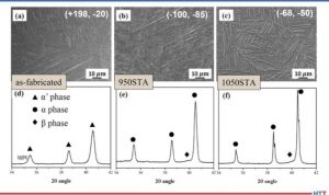
Ti-6Al-4V dumbbell-shaped tensile testing bars were fabricated by DMLS, according to ASTM standards. The microstructure, phase fraction, porosity, and residual stress of as-printed parts were examined and compared to those of the commercial Grade 5 alloy. It was found that the as-printed samples, mainly composed of acicular α’ martensite phase with a small amount of nano-scaled β precipitates, dispersed in the α’ matrix due to rapid cooling during laser processing, whereas the Grade 5 alloy has an α + β two phase with an equiaxed microstructure. The β phase fractions in the as-printed and Grade 5 alloy were 1.6% and 20%, respectively, based on the results of x-ray diffraction refinement. Furthermore, porosity and defects due to lack of fusion or entrapped gas were observed in the DMLS samples. The rapid cooling rate also resulted in residual tensile stress in the as-printed parts.
The microstructure and phase changes due to different heat-treatment processes were examined and compared to those of the commercial Grade 5 alloy. The corrosion behavior of the heat-treated DMLS parts was studied in simulated body fluid by well-established electrochemical methods.
Microstructure: coarsening of the α lath thickness, more spherical β precipitates. Phase identification: narrowed α characteristic peaks (reduced compressive residual stress) Source: WPI
Transformation from α’ to α phase, coarsening of the α lath microstructure, and the development of β phase were observed in samples after heat treatments. The greatest fraction of β phase was obtained in the high temperature annealed sample. Enhanced corrosion resistance was found in all heat-treated samples. The reasons for improved corrosion resistance after heat treatments include: 1) a passive layer that was developed on the sample surface after heat-treatments; 2) increased β phase fraction and size after heat treatments that led to the reduction of the corrosion susceptible sites. Furthermore, only a single passive layer has been observed in the as-printed sample, whereas double passive layers have been observed in samples after heat treatments at temperature higher than 550°C. However, this second layer, which was largely composed of Al2O3 and V2O5, had very low corrosion resistance compared to that of the primary passive layer that was primarily TiO2.
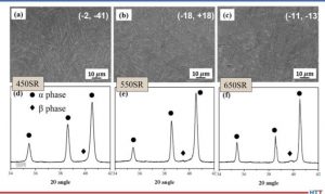
Microstructure: coarsening of the α lath, and grain boundary can be observed Phase identification: narrowing of α characteristic peaks (reduced microstrain, increased grain size) and evolution of β phase Source: WPI
It was also found that the surface roughness had an exponential effect on the corrosion current density and calculated corrosion rate. A rough surface led to a higher corrosion rate, but a rough surface is known to enhance osteointegration. Therefore, surface roughness needs to be adjusted, based on specific applications.
Microstructure: no significant change in the α lath thickness Phase identification: narrowing of α characteristic peaks (reduced microstrain), evolution of β phase Source: WPI
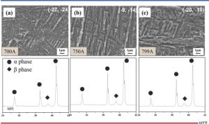
The effect of porosity was analyzed by using a crevice corrosion test. After a one-month immersion in Ringer’s solution at body temperature, pits were found on the Ti-6Al-4V sample surface near the pores in the as-printed samples, which was due to the formation of localized O2 concentration cells near the pore. Porosity in the as-printed parts was confirmed to impair crevice corrosion resistance. To reduce porosity, HIP was applied at three different temperatures. Based on polarization tests and electrochemical impedance spectroscopy tests, different degrees of reduction in porosity and corrosion-current density were observed in samples after HIP; this reduction was most significant after high-temperature HIP at 799°C (1470°F).
In summary, it was found that high temperature heat-treatment enhanced the corrosion resistance of DMLS Ti-6Al-4V parts. HIP was effective in reducing porosity and improving corrosion resistance. HIP below the annealing temperature (799°C, 1470°F) was recommended as a post-treatment for DMLSprintedTi-6Al-4V, to achieve a good corrosion resistance.
References
[1] “Metal Implants and Medical Alloys Market – Global Forecast to 2024,” 2019. https://www.marketsandmarkets.com/Market- Reports/metal-implant-medical-alloy-market-256117768.html.
[2] R. Bothe, et al., “Reaction of bone to multiple metallic implants.” Surgery, Gynecology and Obstetrics, 1940, 71:598–602.
[3] M. Sarraf, E. Rezvani Ghomi, S. Alipour, et al., “A state-of-the-art review of the fabrication and characteristics of titanium and its alloys for biomedical applications,” Bio-des. Manuf., 2022, 5, 371–395. https://doi.org/10.1007/s42242-021-00170-3.
[4] L.-C. Zhang and L.-Y. Chen, “A Review on Biomedical Titanium Alloys: Recent Progress and Prospect,” Adv. Eng. Mater., 2019, 21: 1801215. https://doi.org/10.1002/adem.201801215.
[5] L. E. Murr, S. A. Quinones, et al., “Microstructure and mechanical behavior of Ti–6Al–4V produced by rapid-layer manufacturing, for biomedical applications,” Journal of the mechanical behavior of biomedical materials, 2009, 2(1), 20-32. https://doi. org/10.1016/j.jmbbm.2008.05.004.
[6] A. Hung Dang Nguyen, A. K. Pramanik, Y. Basak, C. Dong, S. Prakash, S. Debnath, I. S. Shankar, Saurav Dixit Jawahir, and Budhi Dharam, “A critical review on additive manufacturing of Ti-6Al- 4V alloy: microstructure and mechanical properties,” Journal of Materials Research and Technology, 2022, 18: 4641-4661. https://doi.org/10.1016/j.jmrt.2022.04.055.
[7] “Direct Metal Laser Sintering (DMLS) Technology,” Additive News. https://additivenews.com/direct-metal-laser-sintering-dmlstechnology/.
[8] O. Cissé, O. Savadogo, M. Wu, and L’H Yahia, “Effect of surface treatment of NiTi alloy on its corrosion behavior in Hanks’ solution.” Journal of Biomedical Materials Research, 2002, 61/ 3 :
339-345. https://doi.org/10.1002/jbm.10114
[9] Sara A. Atwood, Eli W. Patten, Kevin J. Bozic, Lisa A. Pruitt, and Michael D. Ries,”Corrosion-induced fracture of a double-modular hip prosthesis,” The Journal of Bone & Joint Surgery, 2010, 92/ 6: 1522-1525.
[10] Y. Xu, Y. Lu, K.L. Sundberg, et al., “Eff ect of Annealing Treatments on the Microstructure, Mechanical Properties and Corrosion Behavior of Direct Metal Laser Sintered Ti-6Al-4V,” J. of Material Eng and Perform, 2017, 26: 2572–2582. https://doi.org/10.1007/ s11665-017-2710-y
[11] Ibid.
[12] Z. Yang, Y. Xu, R. D. Sisson, & J. Liang, “Factors Influencing the Corrosion Behavior of Direct Metal Laser Sintered Ti-6Al-4V for Biomedical Applications,” Journal of Materials Engineering and Performance, 2020, 29/6: 3831-3839.
About the Authors
Professor Richard Sisson is a key heat treat researcher and lecturer at Worchester Polytechnic Institute. His main research interest is the application of diffusion and thermodynamics to the solution of materials problems. Currently, he is working on modeling the surface treatment of steels and the postprocessing of AM ceramics and metals. His research endeavors have resulted in over 300 publications and over 300 technical presentations.
Dr. Yangzi Xu is currently working at Intel Corporation as a Yield & Module Process Engineer. She received her PhD at Worcester Polytechnic Institute (WPI) and focuses her research on understanding the mechanical and electrochemical properties of AM Ti alloys with different types of heat treatments, and their corrosion performance in biofluid for potential orthopedic applications. Her background includes research in polymer and food science and engineering.
Professor Jianyu Liang is a Professor of Mechanical and Materials Engineering at Worchester Polytechnic Institute, with affiliated appointments in the departments of Civil and Environmental Engineering, Chemical Engineering, and Fire Protection Engineering. Her research work on nanomaterials, AM, agile manufacturing, machine learning for materials science and manufacturing engineering, and sustainability has been funded by NSF, NASA, DoD, ED, and industry. Her work has resulted in over 300 research papers and technical presentations. As an educator, Liang strives to equip students with the confidence, enthusiasm, knowledge, and skills to allow them to enjoy learning throughout their lives.
For more information
Department of Mechanical and Materials Engineering Worcester Polytechnic Institute, 100 Institute Road, Worcester, MA 01609 Or email jianyul@wpi.edu and sisson@wpi.edu
Find heat treating products and services when you search on Heat Treat Buyers Guide.com
Last month, we introduced the importance of radiant tubes in the heat treat industry. We explored the “why” of radiant tubes and skimmed the surface, exploring materials, sizing, shapes, longevity, and installation — all topics we’ll deep dive into in future posts. This month, let’s explore what typically occurs inside a radiant tube.
This column is a Combustion Corner feature written by John Clarke, technical director at Helios Electric Corporation, and appeared in Heat Treat Today's December 2022 Medical and Energyprint edition.
If you have suggestions for topics you’d like John to explore in future columns, please email Karen@heattreattoday.com.
John B. Clarke Technical Director Helios Electric Corporation Source: Helios Electrical Corporation
The radiant tube burner combines fuel and an oxidizer (commonly air) in the presence of a source of ignition. Radiant tube burners differ from burners that are fired into an open furnace. They function to distribute heat as uniformly as possible within the interior of the tube to maximize its temperature and heat transfer uniformity. In some applications, a low rate of heat transfer is acceptable (for example, in the holding zone of a continuous furnace). In that same furnace, a much higher heat transfer rate may be required in the front of the furnace. In all cases, higher heat transfer rates result in higher internal tube temperatures. In most cases, the higher the temperature, the greater the stress on the material.
Within the radiant tube in the visual flame region, the energy is transferred to the inner surface of the tube by convection and radiation. The rate of convective transfer has much to do with the mixing characteristics of the burner in question. Once combustion is complete, the heated products of combustion — CO2 , O2 , H2O, and N2 — continue to flow through the radiant tube. They impart heat to the interior surface of the radiant tube through convections and — in the case of the CO2 and H2 — radiation. The non-polar gases (O2 and N2) are effectively transparent to radiation: neither absorbing nor radiating heat. This transparency poses a problem for the performance of radiant tubes because the combustion process is ideally complete some distance before the end of the radiant tube.
There are a few ways to make use of the heat stored in the O2 and N2 . One way is to stir the mixtures to ensure these gases meet the inside walls of the tube and can convectively transfer their energy. Another way is to insert a “core buster” or other device into the exit end of the radiant tube. This device must be able to withstand the peak temperature of the products of combustion at this point, so it is typically constructed of some ceramic material or a composite of ceramics. As the heated gases pass over this “core buster,” the resistance forces higher flows around the perimeter of the tube, increasing convective transfer. The “core buster” also is convectively heated and can then radiate heat to the inner surface of the tube and, finally, the “core buster” increases mixing of the gases to ensure all remaining hydrocarbons and carbon monoxide are brought into contact with oxygen to complete the oxidation process.
The transfer of heat to the inner surface is dependent on the effective surface area. A tube with a nominal inside diameter of four inches may have a much greater effective surface area due to roughness, which resemble very small peaks and valleys. Anyone who has attempted to walk around a small Caribbean island can attest — it takes a lot longer than you would think by looking at the map and really scares your shipmates when they cannot find you. Cast and composite radiant tubes can be fabricated to increase this effective internal surface area. Tubing can also be equipped with internal fins.[blocktext align="left"]No matter what the construction, ultimately it does no good to transfer heat to the interior of the radiant tube if the tube cannot transfer the same quantity of heat through the exterior to the furnace and work being heated.[/blocktext]
Which mode of control is better? High/Low, proportional, or pulsed? Any method can achieve a uniform tube heat release given the correct burner radiant tube combination. The important thing is that the vigor of the mixing is matched to the length and roughness of the radiant tube. Burner X may be perfectly suited to a short radiant tube but lead to non-uniform heating as the tube length is extended. On the other hand, Burner Y, with a relatively lazy flame, may work perfectly on long tubes with lower heat transfer demands but be unsuitable for short tubes where high heat transfer rates are desired.
In the coming months, we will examine many of these areas in greater detail, and this author can make use of his experience of many failures to inform the readers of what not to do. Then, by extension, we’ll learn how to get more from the furnaces by thinking systematically about their radiant tubes, burners, and controls.
Find heat treating products and services when you search on Heat Treat Buyers Guide.com
Radiant tubes are prevalent in heat treating applications. They are very simple devices: basically, a pipe that enters and exits the work chamber. Geometrically simple — but the considerations of how they should be applied, the optimal materials for their construction, and the best burner to use present a myriad of challenges and opportunities for improvement. As all heat treaters know, radiant tubes represent a significant expense as well as an opportunity to save on maintenance costs and improve furnace performance.
This column is a Combustion Corner feature written by John Clarke, technical director at Helios Electric Corporation, and appeared in Heat Treat Today's November 2022 Vacuumprint edition.
If you have suggestions for topics you’d like John to explore in future columns, please email Karen@heattreattoday.com.
John B. Clarke Technical Director Helios Electric Corporation Source: Helios Electrical Corporation
In the coming months, I hope to challenge the reader to spend some time researching opportunities to improve their use of radiant tubes — that is to improve their performance, both heating rates and efficiency, as well as to extend their life and perhaps improve the uniformity of the furnace being heated.
I apologize in advance if I sound like an economist — “It is this way, but on the other hand . . .” There are a lot of factors to consider when planning to upgrade your radiant tubes, their associated burners, recuperators, mountings, and supports.
To start, let’s answer a simple question: Why do we use radiant tubes? Two reasons come to mind: to protect the furnace atmosphere from the products of combustion and/or to diffuse the release of heat within the furnace or oven chamber to maximize temperature uniformity. In many heat treating applications, even a very small leak will contaminate the furnace atmosphere, damaging the work being processed.
How do we size radiant tubes? Again, it is obvious that we need to have sufficient heated external surface area to transfer the heat to the furnace chamber. This heat transfer will occur through convection and radiation, with the latter mode being more significant as the furnace temperature rises. The rate of convective heat transfer will depend on mass and velocity of air or atmosphere passing over the tubes. The radiant heat transfer rate is a function of the difference between the tubes’ surface temperature and the temperature of the furnace and work being heated. The good news with radiant heat transfer in closed furnaces is that all surfaces in the furnace participate to a degree with the transfer of heat to the work.
There are many shapes for radiant tubes: U-shaped, W-shaped, three legged, as well as systems where the firing and exhaust occur at the same opening, including P-tubes and single-ended tubes. Each has its advantages and disadvantages, which we’ll discuss in future articles.
How about materials? Again, we have a lot of choices. The tubes can be centrifugally cast, fabricated from sheet, or made of some ceramic or composite material. [blocktext align="center"]The formulation of each material varies greatly, and it is important that the material is suitable for the use temperature and chemical composition of the furnace atmosphere as well as always being compatible with the common products of combustion.[/blocktext]
How are the radiant tubes installed? Are the ends welded to a mounting plate, or perhaps a packing gland is employed to seal the tube while allowing some expansion or contraction? Both methods are commonly applied successfully. Composite tubes may have a flange that is clamped at the mounting location, or they may use a packing gland. The tubes may have internal supports within the furnace to prevent sagging. The tubes can be hung vertically, located to the side of, or placed under and over the work being heated.
How long should my radiant tubes last? Simply answered, for as long as practical. As a young person, I was mortified when I dropped a hammer in a customer’s pusher carburizing furnace, and it broke an alloy tube. When I confessed to the plant metallurgist, he laughed and told me the tube I broke was over twenty years old. Other customers may be satisfied if their tubes last 18 months, so there is no simple answer. That said, there may well be opportunities to extend the life of the radiant tubes in your specific application.
We will revisit many of these discussions in later articles, but hopefully this column has whetted your appetite for the next discussion in December: What typically occurs inside the radiant tube? After all, this is the Combustion Corner.
Find heat treating products and services when you search on Heat Treat Buyers Guide.com
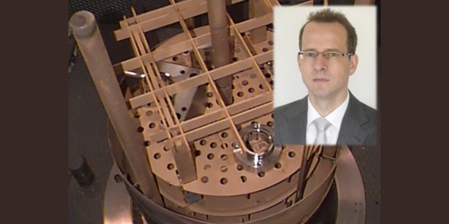
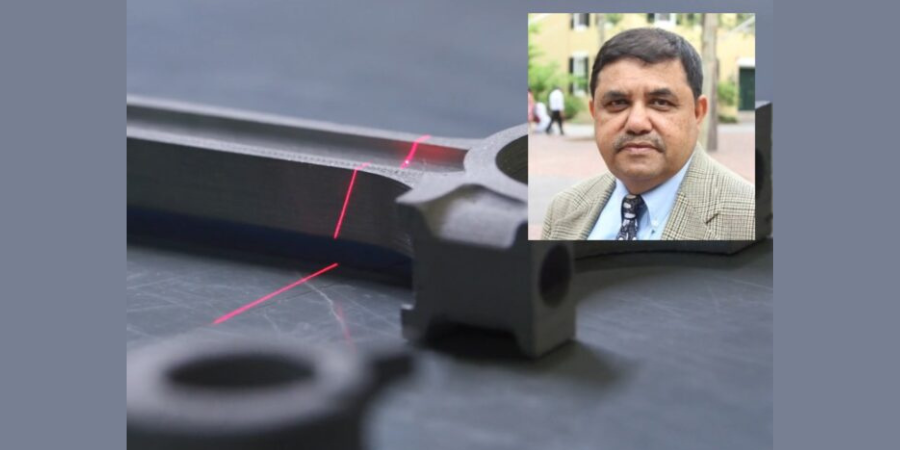
What happens when a lead engineer sticks his head in new advancements in materials from NASA? For the author of this article, it means the successful research and development of a new generation of workpiece carriers and fixtures made from “a high-tech ceramic matrix composite of very strong carbon fiber,” that is, CFC.
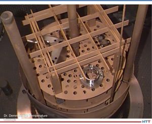
This Technical Tuesday article, written by Dr. Jorg Demmel, founder, 0wner, and President, High Temperature Concept, was first published in Heat Treat Today's November 2022 Vacuum print edition.
Introduction: From NASA to Industrial Heat Treatment
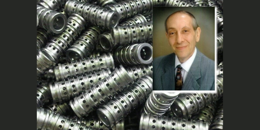
Dr. Jorg Demmel Founder, Owner, President High Temperature Concept
In the mid-1990s, a development in materials from NASA moved into my focus. I was an associate and lead engineer at the Fraunhofer Institute in Stuttgart, Germany, so I posed the question: Could CFC material (carbon fiber-reinforced carbon) substitute for non-abrasion-resistant and brittle graphite as the material used for workpiece carriers in the soldering process of drills? The answer: yes. The story did not end here. This project, which included the automated handling of the drills in some continuous furnaces, was just the first accomplishment. What ensued was a successful research and development of a new generation of workpiece carriers and fixtures made from CFC (“Carbon Fiber Carbon”).
Material Properties and Main Advantages of CFC
Contact us with your Reader Feedback!
CFC (aka, CFRC, or C/C), which stands for carbon fiber-reinforced carbon, is a high-tech ceramic matrix composite of very strong carbon fibers (or fiber rovings) in a compensative carbon (graphite) matrix. Material properties of some relevant heat treatment fixture materials were evaluated, and some are shown in Figure 1. These CFC properties have the following positive effects when used as CFC fixtures for heat treatment:
Figure 1. Left to right for 2D CFC SGL Sigrabond Performance, heat resistant austenitic cast alloy steel ASTM A297-HK (ISO G-X 40 CrNiSi 25-20; 1.4848), wrought and annealed Ni alloy Inconel 601 UNS N06601 (NiCr23Fe15Al; 2.4851) and mechanically alloyed Fe alloy, oxide dispersion strengthened Plansee PM ODS 2000 (Cr Al 21 6; 1.4768).
Because of their low density, CFC fixtures have a lower weight than their steel alloy counterparts (about five times), which reduces the efforts for manual handling.
Because of the increased strength of CFC at high temperature, the fixture weight can be reduced further. Additionally, fixture volume can be reduced — in some applications dramatically — so that, when combined with a specific CFC fixture design, furnace capacities can be increased up to 100%.
The following characteristics of CFC fixtures are responsible for the longer fixture life cycles (up to greater than five times), less workpiece distortion and rework, and make an automatic workpiece handling possible for the first time ever: the low CTE (coeffcient of thermal expansion) value for CFC in the direction of the fiber, the fact that CFC is chemically inert in vacuum or
certain protective atmospheres, has an excellent thermal shock resistance, and it doesn’t grow, creep, or age like metals.
Although the specific heat of CFC is higher, the energy consumption can be reduced and shorter heating up and cooling down times can be reached, resulting in up to 30% shorter process cycle times for the same workpieces.
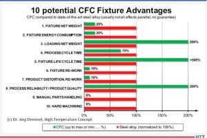
Figure 2. CFC fixture advantages in heat treatment
Figure 2 shows all potential advantages of CFC fixtures compared to state-of the- art steel alloy; a short payback time of the investment with high profitability are possible.
CFC Fixture Suitability in Vacuum Heat Treatment
Since CFC is made of carbon, it is not made for high temperatures above 752°F (400°C) in air or atmosphere with high percentages of oxygen, water vapor, hydrogen, or carbon dioxide for long periods of time. Therefore, vacuum or protective gas atmospheres are, in general, a suitable environment for CFC fixtures.
Table 1. Reaction rates and activation energies for graphite (800 °C; 0.1 bar). Equation (1) is the main combustion reaction, which has the strongest effect and is strongly exothermic (negative change of reaction enthalpies Δ"H). Reaction (2) is the so-called water gas reaction which shows the endothermic oxidation of carbon with vapor. Equation (3) is the Boudouard reaction which occurs endothermic above 700 °C. According to the Boudouard equilibrium the C0/CO2 ratio increases with increasing temperatures and decreasing pressures. Reaction (4) is the methane formation reaction: hydrogen reacts with carbon at temperatures above about 700 °C to CH4. Below 546 °C methane decomposes in carbon and hydrogen.
Table 1 shows the relative reaction rates for graphite according to H. Marsh in Introduction to Carbon Science, 1989 in the “reaction controlled” Zone I up to 1472°F (800°C) under oxygen, steam (H2O) Figure 3. Burning rates of graphite as a function of temperature
Industrial experience shows that CFC under vacuum of < 10-2 mbar at 1472°F or 1832°F (800°C or 1000°C) at a low dew point < -4°F (-20°C) (< 0.1 % vapor content) lasts at least 5,000 hours (real process time). At 3632°F (2000°C), the life is about 2,000 hours. Dew points of about 0°C (about 0.6 % vapor) cause higher reaction rates and reduce lifetime to about 800 to 1,000 hours.
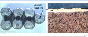
Unwanted Contact Reactions
Contact reactions between the CFC fixtures and the workpieces, primarily made of steel, can lead to changes in the workpieces: for example, carburization of the workpiece in contact with the CFC. It is important to avoid these contact reactions since the properties of the workpieces must under no circumstances be changed in an uncontrolled manner. Neither the chemical composition nor mechanical properties nor the surface may change beyond the permissible tolerance limits. The CFC fixture should also not be subject to any changes that could adversely affect its properties and, above all, its service life.
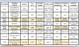
The following materials, consisting of mainly workpiece materials made of steel, were used in direct contact with CFC, especially in heat treatment and brazing. CFC 1501G (SGL), CF222 (Schunk), or CX-27C1 (GTD, Toyo Tanso) were used as CFC workpiece carrier materials. Table 2 gives an overview of the results. The symptoms columns with “none” indicate no problems. The colored cells showed problems. The last column references the application or the results.
Table 2. Contact/carburization test results from field trial, updated 2022
The contact partners and processes in which unwanted contact reactions occurred in the field test (colored in Table 2) and which are not confidential (bold font) are examined more closely in Part 2. See Figure 5 which shows some contact reactions on tempered steel drills after vacuum hardening at 2066°F (1130°C) under vacuum of 0.3 mbar (0.3 hPa or 225 mm Hg or “micron”).
Figure 5. Contact reactions on drill blanks (1.6582) with SiC-coated CFC (Schunk CF222P75 and SGL 1601YI); Scale left about 2:1 and right microsection about 400:1
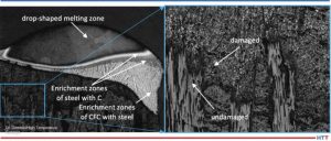
Figure 6 shows some heavy melting reactions of high-speed steel after vacuum hardening at 2264°F (1240°C) under vacuum of 0.1 mbar (0.1 hPa or 75 mm Hg or “micron”).
Figure 6. 1.3343 after contact with CFC CF222 at 2282°F (1250 °C) (left approx. 25:1; right detail 100:1)
The carbon transmission mechanism with unwanted carburization, along with eutectic reaction of some workpieces made of steel with CFC, and some technical solutions will be explained in Part 2 of this article.
References
Atkins, P. W.: Physikalische Chemie. 1. vollst. durechges. u. berichtigter Nachdr.d. 1. Aufl., Weinheim, VCHVerlag, 1988 – ISBN 3-527-25913-9.
Bürgel, R.: Handbuch Hochtemperatur-Werkstofftechnik: Grundlagen, Werkstoffbean-spruchungen, Hochtemperaturlegierungen. Braunschweig, Wiesbaden: Vieweg, 1998. ISBN 3-528-03107-7.
Demmel, J.: Advanced CFC-Fixture Applications, their scientific challenges and economic benefits, In: 30th Heat Treating Society Conference & Exposition, Detroit, MI, USA, 15th Oct. 2019.
Demmel, J.: Werkstoffwissenschaftliche Aspekte der Entwicklung neuartiger Werkstückträger für Hochtemperaturprozesse aus Faserverbundkeramik C/C und weiteren Hochtemperaturwerkstoffen, Dissertation, TU Freiberg, Germany, 2003.
Demmel, J.: Why CFC-Fixtures are a Must for Modern Heat Treaters, FNA 2020 Technical Session Processes & Quality, USA, 30th Sept. 2020.
Demmel, J., et al: Applications of CMC-racks for high temperature processes. In: 4th Int. Conf. on High-Temperature Ceramic Matrix Composites, 3.10.2001, p. A-17.
Demmel, J. und J. Esch: Handhabungs-Roboter sorgt für Wettbewerbsvorsprung. Härterei: Symbiose von neuen Werkstoffen und Automatisierung. In: Produktion (1996), No. 16, p. 9.
Demmel, J. und U. Nägele: CFC revolutioniert die Wärmebehandlung. In: 53. Härterei-Kolloquium, Wiesbaden, 10.10.97. Vortrag und Tagungsbericht.
Demmel, J., Lallinger, H.: CFC-Werkstückträger revolutionieren die Wärmebehandlung. In: Härtereitechnische Mitteilungen 54, No. 5, p. 289-294, 1999.
Eckstein, H.-J., et al: Technologie der Wärmebehandlung von Stahl. 2nd Edition, VEB Deutscher Verlag für Grundstoffindustrie, Leipzig, 1987. ISBN 3-342-00220-4.
Godziemba-Maliszewski, J.; Batfalsky, P.: Herstellung von Keramik-Metall-Verbindungen mit Diffusionsschweißverfahren. In: Technische Keramik, Jahrbuch, Essen, 1 (1988), S. 162-172. ISBN 3-80272141-1.
Grosch, J.: Grundlagen-Verfahren-Anwendungen-Eigenschaften einsatzgehärteter Gefüge und Bauteile, ExpertVerlag, 1994, ISBN 3-8169-0739-3.
Hollemann, A.F.; Wiberg, E.: Lehrbuch der anorganischen Chemie / Hollemann-Wiberg. 91.-100. Aufl ., de Druyter Verlag, 1985 – ISBN 3-11-007511-3.
Kriegesmann, J.: Technische Keramische Werkstoffe. Loseblattwerk mit 6 Ergänzungslieferungen pro Jahr.
Kussmaul, K.: Werkstoffkunde II. Stuttgart, Universität, Lehrstuhl für Materialprüfung, Werkstoffkunde und Festigkeitslehre, Vorlesungsmanuskript, 1993.
Lay, L.: Corrosion Resistance of Technical Ceramics. 1. Aufl ., Teddington, Middlesex, Crown-Verlag, 1983 – ISBN 0-11-480051-0.
Marsh, H.; u.a.: Introduction to Carbon Science. 1. Aufl ., London, Butterworths-Verlag, 1989 – ISBN 0-40803837-3.
Spur, G.: Wärmebehandeln. Berlin, 1987, ISBN 3-446-14954-6.
Samsonow, G.V.: Handbook of refractory compounds. New York, 1980.
Schulten, R.: Untersuchungen zum Kohlenstofftransportmit Carbidbildung in Nickelbasis-legierungen. RWTH Aachen, Fakultät für Maschinenbau, Diss., 1988 Deutsche Keramische Gesellschaft, 1990 following. ISBN 3-87156-091-X.
About the Author: Dr. Jorg Demmel is the founder, owner, and president of High Temperature Concept. He received his Engineering Doctorate in the field of CFC workpiece carriers for heat treatment and served in different leading positions for Volkswagen before moving to the U.S. In this article, Demmel draws on his dissertation, “Material scientific aspects of the development of new Fixtures for high temperature processes made of fiber-composite ceramics C/C and other high temperature materials” (Technical University Mining Academy Freiberg, Germany, 2002/3), and his personal experiences. For more information Contact Jorg at jorg.demmel@high-temperature-concept.com
Find heat treating products and services when you search on Heat Treat Buyers Guide.com
Part discoloration after vacuum heat treating? What can heat treaters do to prevent this? In this best of the web, Q&A-style article, witness the heat treating industry gather around to exchange ideas and find a solution to the problem. Part position, backfill gas level, contaminated quench gas, or an air leak could all be to blame in this Technical Tuesday.
Dan Herring weighs in on the issue as well. To read The Heat Treat Doctor's®diagnosis, click the link below. Learn how the color and position of the discoloration give clues as to the source of the problem.
An excerpt:
"So, what else could be happening? Let The Doctor add a few thoughts to the discussion. First, the fact that the discoloration (staining) is brown in coloration suggests that the oxide is forming on the part surface during cooling when the temperature is in the range of (approximate) 245ºC – 270ºC (475ºF – 520ºF). This is supported by the fact that the oxidation does not occur “during natural cooling” (which we assume to mean cooling under vacuum). Second, the fact that the discoloration is more evident at the bottom of the load suggests the phenomenon is (gas exposure) time dependent, that is, the longer the parts take to cool through the critical range, the greater the chance for discoloration."


 Find heat treating products and services when you search on Heat Treat Buyers Guide.com
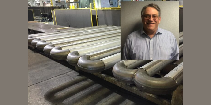


 Last month, we introduced the importance of radiant tubes in the heat treat industry. We explored the “why” of radiant tubes and skimmed the surface, exploring materials, sizing, shapes, longevity, and installation — all topics we’ll deep dive into in future posts. This month, let’s explore what typically occurs inside a radiant tube.