Technical Tuesday

CFC Fixture Advantages and Challenges, Part 2

OCWhat are the factors that lead to carburization and carbon transmission? How can heat treater avoid these unwanted reactions? Discover the challenges of CFC fixtures and the steps heat treaters can take to mitigate these challenges.

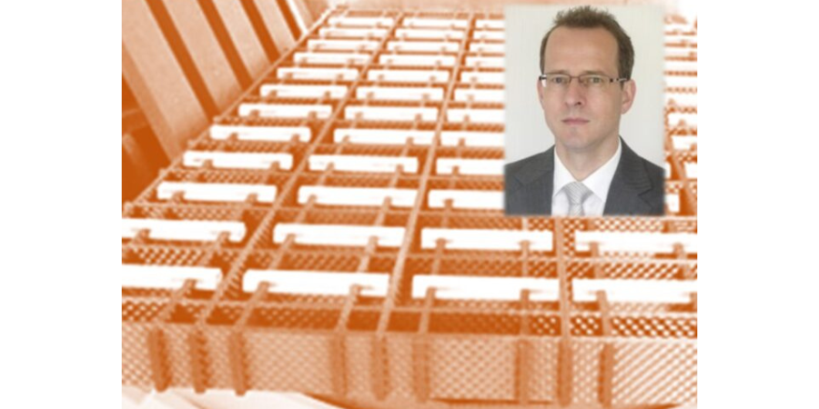
This Technical Tuesday article, written by Dr. Jorg Demmel, founder, 0wner, and president, High Temperature Concept, was first published in Heat Treat Today's March 2023 Aerospace Heat Treating print edition.


Introduction

Dr. Jorg Demmel
Founder, Owner, President
High Temperature Concept

The main advantages of CFC fixtures were introduced in “CFC Fixture Advantages and Challenges in Vacuum Heat Treatment, Part 1,” which was released in Heat Treat Today’s November 2022 publication. This included a discussion of the limits of CFC in vacuum and protective atmosphere heat treatment. Successful applications of CFC workpiece carriers in heat treatment were presented along with field test results that included a brief discussion of undesired contact reactions (i.e., carburization and melting of parts). In Part 2 of this paper, the mechanisms involved with carburization and carbon transmission due to direct contact of parts with CFC fixtures will be further explained.

Mass Transfer from CFC Fixtures

Contact us with your Reader Feedback!

The mass transport of carbon from CFC fixtures into steel parts at high temperatures will be examined in the following areas:

  1. Reactions in oxygen (i.e., the reaction medium)
  2. Transport of carbon in CFC during exposure to oxygen
  3. Transfer mechanism into the steel parts
  4. Diffusion of carbon into the steel parts
  5. Part reactions (melting, carbide formation)

Figure 1: 1.6582 steel samples and GDEOS depth profile analysis
Source: Dr. Jorg Demmel, High Temperature Concept

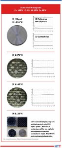
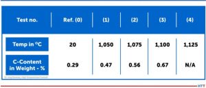
CFC samples were tested in contact with steel samples under laboratory conditions in a vacuum of 7.5 x 10⁻⁷ Torr (1 x 10⁻⁶mbar). Results of the contact with CFC for steel samples at different temperatures are presented to the left (Figure 1). It is important to note that:

  • Sample (0) is the reference sample and had no exposure to the contact test.
  • Sample (0’) is the back side of Sample (0).
  • Sample (1) is the contact side at 1922°F (1050°C).

All three samples are visually identical, therefore only one is shown. Sample (2) at 1967°F (1075°C) and Sample (3) at 2012°F (1100°C) exhibited a distinct visual surface pattern after CFC contact. This was analyzed by Glow Discharge Optical Emission Spectroscopy (GDOES) and the test location (gray spot) clearly observed on Samples (2) and (3). For Sample (4) run at 2057°F (1125°C), the CFC was found to have adhered to the steel surface.

The carbon content in 10mm depth measured with GDOES (see the profiles in Figure 1) increased from initially 0.29 weight-% for the 1922°F (1050°C) test, although nothing was visible on metal surfaces. For carbon contents, see Table 1.

Table 1. Carburizing of 1.6582-samples in 10 µm depth after CX-27C1-contact (GDOES)
Source: Dr. Jorg Demmel, High Temperature Concept

CFC Reactions with Oxygen

The chemical reactions of CFC with various gases are essential in Step 1 (referenced in Part 1 of this article) and an indicator of chemical thermal suitability.

In the case of the unwanted contact carburization considered above is similar, in a sense, to carburization of steel in contact with carbon powder or granulate. However, the actual carburization mechanism, which occurs between approximately 1616°F and 1697°F (880°C and 925°C), does not take place directly via the carbon contact but is based on the fact that solid carbon reacts with atmospheric oxygen according to the Equation Table to form carbon dioxide (CO2).

Equation Table. Reaction rates and activation energies for graphite (800°C; 0.1 bar)
Source: Dr. Jorg Demmel, High Temperature Concept

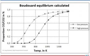
Carbon monoxide (CO) is then formed from CO2 by the Boudouard reaction (Equation 3). At high temperatures and low pressures (see Figure 2), almost only CO is present.

Figure 2. Boudouard equilibrium
Source: Dr. Jorg Demmel, High Temperature Concept

Transport of Carbon

The carbon carrier must be transported to the surface of the parts.

The cases considered in Part 1 of this article were conducted in vacuum, that is in the absence of a carburizing atmosphere. The laboratory tests were even carried out in a vacuum as low as 7.5 x 10⁻⁷ Torr (1 x 10⁻⁶mbar). Nevertheless, part surface reactions were observed.

Transfer Mechanism into the Steel Parts

Theoretically, carbon from the CFC fixtures can be transferred into the steel via solid phase (as opposed to gaseous phase) reactions. Gas particles can be adsorbed by surfaces via physisorption and/or chemisorption. The author’s personal research experience has shown that metal samples usually oxidize after a short time, even in a high vacuum of 7.5 x 10⁻⁷ Torr (1 x 10⁻⁶mbar). In particular, elements such as iron, molybdenum, and chromium have a strong ability to chemically adsorb oxygen or CO.

Furthermore, there is a disproportionately large amount of adsorbed oxygen in the CFC samples. CFC has open porosities as high as 30%. CFC in industrial practice is never completely evacuated. So, there is a disproportionately large amount of oxygen present in CFC fixtures.

It can be assumed that oxygen repeatedly escapes from the CFC and is initially available in the contact area. Proof of this can be provided by the GDOES analysis. Outside the contact areas, no (gas) carburization took place (as evidenced by the non-contact side of steel samples).

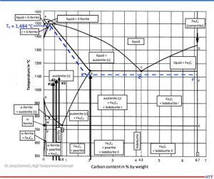
The oxygen and carbon surplus combined with close contact lead to complete reaction of oxygen creating carbon dioxide as in Equation (1). Because of the carbon surplus, almost only carbon monoxide is produced as shown in Equation (2). Because of the very close contact between CFC and steel, C-adsorption by gamma iron and desorption of carbon dioxide as in Equation (5) takes place:

Equation 5
Source: Dr. Jorg Demmel, High Temperature Concept

Since carbon dioxide immediately comes in contact with carbon in the CFC again, carbon monoxide is produced according to Equation (3). In other words, carbon dioxide regenerates immediately and the reaction starts again.

Direct carbon transfer from CFC to metal via solid phase is very unlikely since carbon atoms in CFC are firmly bound in rings.

Diffusion of Carbon in the Steel Parts

In solids, the surface diffusion usually takes place at significantly higher diffusion rates than in the bulk material. The thermodynamic driving force of diffusion or carburizing reactions is the difference in carbon activity for a specific concentration in the austenite to that of the reaction medium. The carbon activity is the ratio of the vapor pressure of the carbon in state under consideration to vapor pressure of pure carbon (graphite/CFC). Alloying elements of the steel influence the activity of the carbon.

Part Reactions (Melting and Carbide Formation)

Steel can begin to melt if, at the given values for temperature and pressure, a partially liquid phase is reached, that is, the solidus line in the phase diagram is exceeded. At even higher temperatures, the liquidus temperature can be reached and steel is completely liquid.

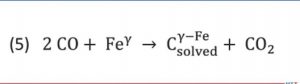
According to metastable iron-carbon diagram phase diagram (Figure 3), a steel such as SAE/ AISI 4340 (34CrNiMo6) alloy (DIN 1.6582) with around 0.47% by weight percent carbon does not begin to melt at 1922°F (1050°C), the exposure temperature for Sample (1), or Sample (2) at 0.56% and 1967°F (1050°C) for Sample (3) with 0.67% for 2012°F (1100°C). The iron-iron carbide phase diagram applies to steels with less than 5% (by mass) of alloying elements and thermodynamic equilibrium, so it is an accurate representation for a SAE/AISI 4340 (34CrNiMo6) alloy.

Figure 3. Metastable equilibrium diagram Fe-Fe3C for steel (good fit for 1.6582)
Source: Dr. Jorg Demmel, High Temperature Concept

A calculation of the solidus temperature shown on the iron-iron carbide diagram (Figure 3), which is dependent on the carbon content and alloying elements, yields a value of 2703.2°F (1,484°C) (J’).

For an SAE/AISI 4340 (34CrNiMo6) steel (DIN 1.6582) with 0.3% C and one for 0.5% C, the calculated solidus temperature is 2640°F (1449°C). This is shown on the J’-E’ blue dotted line in Figure 3. In other words, a lower solidus line (cf. dashed blue line in Figure 3) and thus a slight reduction in austenite phase region.

The iron-carbon diagram also indicates that melting of surfaces that have absorbed carbon (e.g., Sample No. 2) will occur at 1967°F (1075°C). This value is within approximately 90°F (50°C) of the temperature used (dotted line E’-C’-F’). From this information we can conclude that the observations seen in Figure 1 are not the result of melting, but rather imprints due to surface softening.

The melting (c.f., Figure 1) observed in Test No. 4, which occurred at 2057°F (1125°C) is likely due to partial carburization of the steel surface and exceeding the solidus temperature. A micrograph confirms eutectic melting and high carbon content, which could also be indirectly confirmed by hardness measurement.

Carbide Formation

Additional reactions can occur between carbon absorbed from the CFC fixtures and the steel parts due to either separation of carbides (e.g., iron carbide in the form of secondary cementite) or carbide formation with alloying elements such as Ti, V, Mo, W, Cr, or Mn (listed in decreasing tendency to form carbides).

Table 2. Reactions between C and metal
Source: Dr. Jorg Demmel, High Temperature Concept

Table 2 lists various elements in alphabetical order that react with carbon above the specified temperatures to form reaction products mentioned, primarily carbides. It should be noted that the temperatures listed apply only to pure metals and pure carbon. As such, they provide only rough approximations of a temperature at which a reaction might begin.

Countermeasures

There are several measures to avoid these unwanted reactions:

  • Ceramic oxide coatings such as aluminum oxide (Al2O3) or zirconium oxide (ZrO2) layers placed onto the CFC
  • Hybrid CFC fixtures having ceramics in key areas to avoid direct contact with metal workpieces
  • Alumina composite sheets
  • Boron nitride sprays
  • Special fixtures made of oxide ceramics

An yttrium-stabilized zirconium oxide layer (93/7) was applied to CF222 by thermal plasma spray and tested successfully (see Figure 4).

Figure 4. Yttrium-stabilized zirconium oxide layer with an average layer thickness of 110µm on CF222 material. The photograph on the right shows a hybrid CFC fixture.
Source: GTD Technologie Deutschland

Summary

It is important to consider the specific process conditions in advance so that unwanted reactions — from carburization to catastrophic melting of the workpieces — can be avoided. Effective countermeasures can be taken.


References

Atkins, P. W.: Physikalische Chemie. 1. vollst. durechges. u. berichtigter Nachdr.d. 1. Aufl ., Weinheim, VCHVerlag, 1988 – ISBN 3-527-25913-9.

Bürgel, R.: Handbuch Hochtemperatur-Werksto technik: Grundlagen, Werksto bean-spruchungen, Hochtemperaturlegierungen. Braunschweig, Wiesbaden: Vieweg, 1998. ISBN 3-528-03107-7.

Demmel, J.: Advanced CFC-Fixture Applications, their scientific challenges and economic benefits, In: 30th Heat Treating Society Conference & Exposition, Detroit, MI, USA, 15th Oct. 2019.

Demmel, J.: Werkstoffwissenschaftliche Aspekte der Entwicklung neuartiger Werkstückträger für Hochtemperaturprozesse aus Faserverbundkeramik C/C und weiteren Hochtemperaturwerkstoffen, Dissertation, TU Freiberg, Germany, 2003.

Demmel, J.: Why CFC-Fixtures are a Must for Modern Heat Treaters, FNA 2020 Technical Session Processes & Quality, USA, 30th Sept. 2020.

Demmel, J., et al: Applications of CMC-racks for high temperature processes. In: 4th Int. Conf. on High-Temperature Ceramic Matrix Composites, 3.10.2001, p. A-17.

Demmel, J. und J. Esch: Handhabungs-Roboter sorgt für Wettbewerbsvorsprung. Härterei: Symbiose von neuen Werkstoffen und Automatisierung. In: Produktion (1996), No. 16, p. 9.

Demmel, J. und U. Nägele: CFC revolutioniert die Wärmebehandlung. In: 53. Härterei-Kolloquium, Wiesbaden, 10.10.97. Vortrag und Tagungsbericht.

Demmel, J., Lallinger, H.: CFC-Werkstückträger revolutionieren die Wärmebehandlung. In: Härtereitechnische Mitteilungen 54, No. 5, p. 289-294, 1999.

Eckstein, H.-J., et al: Technologie der Wärmebehandlung von Stahl. 2nd Edition, VEB Deutscher Verlag für Grundstoffindustrie, Leipzig, 1987. ISBN 3-342-00220-4.

Godziemba-Maliszewski, J.; Batfalsky, P.: Herstellung von Keramik-Metall-Verbindungen mit Diffusionsschweißverfahren. In: Technische Keramik, Jahrbuch, Essen, 1 (1988), S. 162-172. ISBN 3-80272141-1.

Grosch, J.: Grundlagen-Verfahren-Anwendungen-Eigenschaften einsatzgehärteter Gefüge und Bauteile, ExpertVerlag, 1994, ISBN 3-8169-0739-3.

Hollemann, A.F.; Wiberg, E.: Lehrbuch der anorganischen Chemie / Hollemann-Wiberg. 91.-100. Aufl ., de Druyter Verlag, 1985 – ISBN 3-11-007511-3.

Kriegesmann, J.: Technische Keramische Werkstoffe. Loseblattwerk mit 6 Ergänzungslieferungen pro Jahr.

Kussmaul, K.: Werkstoffkunde II. Stuttgart, Universität, Lehrstuhl für Materialprüfung, Werkstoffkunde und Festigkeitslehre, Vorlesungsmanuskript, 1993.

Lay, L.: Corrosion Resistance of Technical Ceramics. 1. Aufl ., Teddington, Middlesex, Crown-Verlag, 1983 – ISBN 0-11-480051-0.

Marsh, H.; u.a.: Introduction to Carbon Science. 1. Aufl ., London, Butterworths-Verlag, 1989 – ISBN 0-40803837-3.

Spur, G.: Wärmebehandeln. Berlin, 1987, ISBN 3-446-14954-6.

Samsonow, G.V.: Handbook of refractory compounds. New York, 1980.

Schulten, R.: Untersuchungen zum Kohlenstofftransportmit Carbidbildung in Nickelbasis-legierungen. RWTH Aachen, Fakultät für Maschinenbau, Diss., 1988 Deutsche Keramische Gesellschaft, 1990 following. ISBN 3-87156-091-X.


About the Author: Dr. Jorg Demmel is the founder, owner, and president of High Temperature Concept. He received his Engineering Doctorate in the field of CFC workpiece carriers for heat treatment and served in different leading positions for Volkswagen before moving to the U.S. In this article, Demmel draws on his dissertation, “Material scientific aspects of the development of new Fixtures for high temperature processes made of fiber-composite ceramics C/C and other high temperature materials” (Technical University Mining Academy Freiberg, Germany, 2002/3), and his personal experiences. For more information, contact Jorg at jorg.demmel@high-temperature-concept.com


Find heat treating products and services when you search on Heat Treat Buyers Guide.com


CFC Fixture Advantages and Challenges, Part 2 Read More »

Reverse Engineering Aerospace Components: The Thought Process and Challenges

op-ed

You can take the aircraft apart, but can you put it back together? Reverse engineering, as anyone who has ever taken apart the TV remote will tell you, is more complicated than it first appears. It is, however, far from impossible. Learn the essential steps to reverse engineering, the role of heat treating, and the challenges the thought process presents.

For this Technical Tuesday piece, take a few minutes to read Jonathan McKay's, heat treat manager at Thomas Instrument, article drawn from Heat Treat Today's March Aerospace Heat Treating print edition. Heat Treat Today is always pleased to share pieces from one of our 40 Under 40 alumnus like Jonathan!

If you want to share ideas about the aerospace industry, our editors would be interested in featuring it online at www.heattreattoday.com. Email Bethany Leone at bethany@heattreattoday.com with your own contributions!


Contact us with your Reader Feedback!
Jonathan McKay
Heat Treat Manager at Thomas Instrument
Source: Thomas Instrument

Reverse engineering (RE) is the process of taking a component or design and dissecting it all the way down to the raw material. Reverse engineering can range from a singular component such as a piston or gear, to multiple components that make up an overall assembly such as an engine or mechanical actuator. This process allows engineers to analyze and gain an understanding of a component’s overall function and design through deductive reasoning. RE can range in the type of analysis, from geometric measurements and material analysis to electrical or mechanical testing. Each analysis reveals clues of how something can be reproduced. The idea of reverse engineering is to look beyond what’s in front of you and find the unexposed clues that can show why something was designed or possibly the thought process of the original designer.

Reverse engineering typically happens through a third-party manufacturer usually not affiliated with the original equipment manufacturer (OEM). Often this is done because the original manufacturer no longer supports the product, or the original design is outdated and needs to be modernized to improve efficiency, functionality, or life expectancy. To put this in perspective, the U.S. Airforce received its first B-1 Bomber in 1984. Since then, over 100 aircrafts have been delivered. After nearly 50 years the aircraft is still flying, but many OEM manufacturers have moved on to newer programs, thus allocating their capabilities and capacity towards the present and future market demands. This creates a market for fabrication of replacement components and assemblies to support aging platforms. In most cases, the OEM’s retain proprietary data thus creating a need for RE processing.

"[T]he U.S. Airforce received its first B-1 Bomber in 1984.
Source: Unsplash.com/midkiffaries

With aerospace products in particular and specifically aging aircrafts, one will encounter obsolescence issues. The goal is to maintain the aircraft with replacement parts that conform to all form, fit, and function requirements while also assuring they have proper life expectancy with respect to maintenance cycles. With this in mind, you typically work with low volume production and invest more time into the design and planning phase of the process. When engaged in this process, it is critical that one understands and implements a fabrication plan that will yield a product that is equivalent or better than that of the OEM. Some engineers would say “Well, let’s make it bigger and better,” but with aerospace components this is not always the case. Typically, the main focus is to replicate the original design intent to the best of your ability because you have a specific footprint and weight to maintain as well as functionality. The exchangeability of the original design and RE design is key. The reverse engineered product needs to possess the same functional and physical characteristics and be equivalent in the performance, reliability, and maintainability. This allows both items to be exchanged without concern for fi t, performance, or alterations to its adjoining component(s).

Another key point in RE processing could be to limit long lead phases by minimizing the need for additional qualification testing where possible. As plating, heat treat, or materials begin to deviate from the initial design, you must consider requalification testing to prove those changes are not detrimental to the application and do not cause more harm than good. Sometimes engineers create features within a design that are meant to be a weak point; this prevents a more critical component from breaking or being destroyed. When you begin to make deviations, it may push the weak point closer to the critical component.

While there are certainly many steps to RE, the essential steps include:

  1. Collect as much data as possible from an external standpoint without destroying or disassembling; i.e., note the overall measurements, orientation, special features, electrical or mechanical properties, etc. It is also a good idea to analyze mating components and/or the system in which the component is utilized. Mating parts are a big part of the discovery; the mating parts can help determine what alternate materials, plating, heat treat, or finishes can be used.
  2. Start creating preliminary drawings with detailed dimensions, notes, and features that were inspected from Step 1.
  3. Slowly disassemble the part (if an assembly) and inspect key features and create preliminary drawings for sub-assembly components. In some cases, it helps to reassemble the product to ensure an understanding of how it goes back together in order to optimize the assembly process once new components are manufactured.
  4. Evaluate the product(s). Conduct material analysis to acquire chemical and mechanical property data. This will aid in defining the appropriate layout for machining, material conditioning (i.e., heat treatment), external finishes/coatings, etc.

While the design and planning phase may pose some challenges, the more critical challenges that occur during reverse engineering are in the execution of the manufacturing, assembly, and qualification testing. To elaborate, once you begin machining and processing components, there may be special methods of manufacturing that require discovery because standard methods may not have worked when the OEM produced it. When this happens, you go back and forth on updating and fine-tuning the process plans, fixturing, programs, etc. Sometimes this means scrapping parts and starting over or validating if parts are still usable for prototyping. Along the same lines, when the process progresses into the assembly and testing phase, engineers typically discover variability, errors, or weak points that require adjustments. In those cases, the engineer’s drawings must be revised. A large percentage of these issues can be limited through experience with similar components or assemblies, but in most cases, there is a lot of analysis and some trial-and error involved in the manufacturing, assembly, and testing phase that is not apparent upon initial RE processing.

References:

  1. Boeing. “The Bone.” https://www. boeing.com/defense/b-1b-bomber/
  2. DLA. “Master List of Technical and Quality Requirements Version 14.”
  3. MIL-STD-280A. “Handbook for definitions of item levels, item exchangeability, models, and related terms.”
  4. DOD Washington, D.C. 20301.

Special thanks to David V. Jones and Thomas R. Blackburn IV at Thomas Instrument for their input on this topic.

About the Author:

Jonathan McKay is a mechanical engineer at Thomas Instrument, a company specializing in reverse engineering critical aerospace components. At the company, he is manning the establishment of heat treat operations, has created procedures and process plans for Thomas Instrument to be an approved heat treater for an aerospace prime, and has attained Nadcap accreditation for heat treat.

Contact him at Jonathan.mckay@thomasinstrument.com


Find heat treating products and services when you search on Heat Treat Buyers Guide.com


Reverse Engineering Aerospace Components: The Thought Process and Challenges Read More »

How Tip-Ups Forever Transformed Brake Rotor Manufacturing

OC

Are your brake rotors heat treated? Travel back in time to discover how ferritic nitrocarburizing (FNC) became the heat treatment of choice for automakers’ brake rotors and why the tip-up furnace forever altered the production process for this part.

This Technical Tuesday article is drawn from Heat Treat Today's February Air & Atmosphere Furnace Systems print edition. If you have any information of your own about heat treating brake rotors, our editors would be interested in sharing it online at www.heattreattoday.com. Email Bethany Leone at bethany@heattreattoday.com with your own ideas!


The Problem: Brake Rotor Corrosion

Michael Mouilleseaux
General Manager at Erie Steel, Ltd.
Sourced from the author

In the early 2000s, corrosion was one of the top three issues that U.S. automotive manufacturers found negatively affected the perception of the quality of their cars. Brake rotors are made of cast iron. These components sit out in the elements, and in places like the U.S. Midwest where salt is often used on the roads, unprotected steel or iron will corrode or rust. Even on the coast, there is salt water in the air.

Contact us with your Reader Feedback!

What does rusting cause? The rotor rusts, and first, the cosmetics are negatively affected (i.e., rusty appearance). But more importantly, the first time you step on the brakes, it squeals like a pig, the vehicle shudders, and the driver feels pulsing in the pedal. He’ll also feel it in the steering wheel because the amount of rust coating one area is different from the amount of rust that’s on another. So, these brand new, forty- to seventy-thousand-dollar cars have orange rust over the brake rotor and a shaky drive. . . it’s not a good look!

Now, this is just a superficial coating of rust that will eventually abrade away; the rotor will look alright, the vehicle will stop better, and it won’t squeal. However, since the rust on the rotor wears off unevenly, the car may never have smooth braking.

A Move to FNC

In the early 2000s, all the big players were looking to FNC (ferritic nitrocarburizing) as a solution to corrosion, including Bosch Braking Systems, Ford, General Motors, Akebono, and the truck manufacturers. FNC was becoming popular since the process adds a metallurgical layer — called the “white layer” or “compound zone” — to the part, providing corrosion resistance and the bonus of improving wear.

Source: Oleksandr Delyk/Adobe Stock

To the OEMs, the benefits were perceived as:

  1. The corrosion issue had an answer.
  2. The life of the rotor doubled from roughly 40,000 to 80,000 miles. Although that meant half as many aftermarket brake jobs compared to before, consumers perceived it as a real advantage.
  3. The rotors generated less dust. Brakes generate dust particles as the result of abrasion of the pads and the rotors. This particulate dust has been identified as both an environmental and a health concern. Now, flash forward to 2022: Electric vehicles are largely displacing the need to control emissions from ICE (internal combustion engine) vehicles. So, the new European standard on vehicle emissions implemented a requirement to control this dust that is harmful to the environment and which EV and traditional brake systems can emit.

But there were certain technical and practical challenges that automotive manufacturers faced when trying to implement this process at scale.

#1 Distortion. Brake rotors may distort during FNC. Since rotors are (gray iron) castings, the process temperature for FNC may stress relieve the rotor, causing it to change shape or distort, rendering it unusable as a disc brake rotor. It was determined that if the rotor castings were stress relieved prior to machining and FNC, the distortion issue was rendered moot.

#2 Loss of Necessary Friction. FNC gives the white layer on the surface of a part with a diffusion zone underneath. The compound zone has a very low coefficient of friction, which means excellent wear properties. However, manufacturers want friction between the rotor and the brake pads to slow the car down. Reducing the friction on the rotors extends the braking distance of the car.

". . .[M]anufacturers want friction between the rotor and the brake pads to slow the car down."
Source: Unsplash.com/Craig Morolf
Let me illustrate this: I ferritic nitrocarburized a set of brake discs for Bosch Braking Systems, which eventually went to Germany and then on a vehicle. The customer absolutely loved the corrosion resistance, but when it was time for the downhill brake test, the car went straight through an instrument house because the brakes couldn’t stop the car! Lesson: For rotors treated with FNC, the brake pads need to be made from a different frictional material!

#3 Cost. Overcoming the technical issues is simple. Stress relieving the casting at FNC temperatures before machining it would help the parts machine better and would eliminate distortion. Modifying the FNC process could reduce the depth of the white layer and, paired with the correct friction material, the acceptable braking capabilities were restored. Yet these additional steps presented a new challenge: higher costs.

The practical constraints of FNC in conventional batch or pit furnaces strained efforts to be cost-effective. The load (size) capacity of the conventional equipment, in conjunction with the time constraints of the FNC process presented a dilemma, as the OEMs’ benchmark was about one dollar per rotor.

Here Comes the Tip-Up

With traditional furnaces for FNC, there was just no way to reach the economics that were necessary for it. A bigger pit furnace might be the way to go, but they really weren’t big enough. So, here comes the tip-up.

Traditionally, a tip-up furnace has been used for processes with just air, no atmosphere. With direct fired burners, the furnace is used for tempering, stress relieving, annealing, and normalizing. Everything loads into the box, gets fired, and unloads, similar to a car-bottom furnace. With the appropriate external handling systems parts could be retrieved from the furnace and then quenched. This additional process increased the usefulness of the equipment and allowed for the processing of tubes, bars, big castings. . . big forgings for the oil industry and the like.

The question of how to heat treat brake rotors on a large scale still needed to be answered. It required a large, tightly sealed furnace with atmospheric integrity for excellent temperature uniformity. In ferritic nitrocarburizing, the processing range is about 950°F to 1050°F. It is well known that properties vary significantly across the temperature range. And they needed to be optimized to create the appropriate frictional properties for the rotors.

So, the answer was: Let’s make a tip-up furnace that can be sealed for atmospheric integrity, has the appropriate temperature uniformity, and can circulate gas evenly. A lot of this would have to be iterative — create, test, compare, repeat.

Tip-up furnace from Gasbarre Thermal Processing Systems
Source: Gasbarre Thermal Processing Systems

The development of the perfect tip-up was essentially the work of one furnace manufacturer and one heat treater who together changed the industry.

American Knowhow Makes the Perfect Tip-Up

In the early 2000s, heat treaters worked with OEMs to develop a cost-efficient process in a tip-up. Manufacturers and service providers tested different methods, including atmosphere FNC and salt bath FNC.

By 2009, the perfect atmosphere furnace was complete and high volume brake rotors began to be processed for General Motors. The furnace manufacturer was JL Becker, Co., acquired by Gasbarre in 2011. The commercial heat treater was Woodworth, Inc., located in Flint, MI. Together, they spent a lot of time and money looking into FNC and figuring out how to make it work in a tip-up furnace.

General Motors was the first one to get on board, utilizing the FNC processed rotors on their pickup trucks and big SUVs, like the Escalade and Tahoe. Ford was not far behind using it on their F150 pickup truck. I was shocked the first time I saw the commercial: a Silverado pickup truck, out in the snow, and the speaker saying, “We now have an 80,000-mile brake system because of a heat treating process called FNC!”

It’s a great story of American knowhow and a collaborative effort between someone who saw a need and someone else who saw the way. To this day, if you want to get a replacement set of brake rotors for your car, go to a place like AutoZone; they will tell you that the difference in cost between the OEM parts and an off-brand is the fact that the off-brand is not heat treated.

About the author: Michael Mouilleseaux has been at Erie Steel, Ltd. in Toledo, OH, since 2006 with previous metallurgical experience at New Process Gear in Syracuse, NY, and as the Director of Technology in Marketing at FPM Heat Treating LLC in Elk Grove, IL. Having graduated from the University of Michigan with a degree in Metallurgical Engineering, Michael has proved his expertise in the fi eld of heat treat, co-presenting at the Heat Treat 2019 show and currently serving on the Board of Trustees at the Metal Treating Institute.

Contact Michael at MMouilleseaux@erie.com


Find heat treating products and services when you search on Heat Treat Buyers Guide.com


How Tip-Ups Forever Transformed Brake Rotor Manufacturing Read More »

How Clean is Clean Enough?

OC

How clean is clean enough? Insufficient cleaning before heat treating can interfere with results; insufficient cleaning after heat treating can impact perception of the part. Discover four methods of measuring part cleanliness that can take place within your heat treat operations in this article provided by SAFECHEM Europe GmbH.

This Technical Tuesday article is drawn from Heat Treat Today's March Aerospace Heat Treating print edition. If you have any information of your own about cleaning after heat treating, our editors would be interested in sharing it online at www.heattreattoday.com. Email Bethany Leone at bethany@heattreattoday.com with your own ideas!


Previously we talked about the importance of cleaning for demanding heat treat applications — in particular gas nitriding, or ferritic nitrocarburizing (FNC), low pressure carburizing (LPC), and brazing. So, if cleaning is a nonnegotiable for certain heat treatment processes, one might ask: how clean is clean enough?

Contact us with your Reader Feedback!

The basic definition of clean is removing unwanted substances, particles, and contaminations. However, when applied to surface cleaning, “clean enough” is determined by what you want to do next in your processing. Parts are generally clean enough if satisfying outcomes can be achieved in the subsequent application.

First, Do You Know the Expectations?

Unlike measuring hardness, monitoring or determining part cleanliness is by no means a straightforward matter.

There are two different kinds of contaminations to consider:

  1. Particle contaminations
  2. Film-type contaminations

Types of contamination
Source: SAFECHEM Europe GmbH

Whereas there are industry definitions or standards for particle contaminations (e.g., VDA-19 or ISO-16232 for the automotive industry), standards for film-type contaminations are not yet fully established.

This inadequacy also explains why many companies do not fully know what to expect when it comes to cleanliness, and they do not fully grasp the potential impact that insufficient cleaning could cause.

Especially when it comes to the heat treat industry, it is important to differentiate between the component cleanliness requirements before and after heat treatment.

Film-type contaminations are the primary factor which could negatively impact heat treat results. Requirements on particle contaminations (VDA-19) usually come from the automotive industry and need to be ensured/monitored after heat treatment.

Therefore, a distinction must be made between a) surface requirements for heat treatment and b) client cleanliness requirements on the final components.

What Is the Right Measurement Method?

The analysis of film-type contaminations and particle contaminations are two different subject matters. Measurement methods for one cannot replace the measurement methods for the other. Often, it is quite common for companies to have requirements on both film-type contaminations (e.g., surface energy in dyne/cm or mN/m) and particle contaminations (e.g., max. particle load) in their component drawings.

Some common measurement methods for determining contaminations include:

  1. White wipe test: A simple visual inspection test using a clean and dry white wipe to wipe across the surface for the detection of colored residues. Because contaminations can negatively impact heat treat results, inspection should take place prior to heat treatment. The test is limited to colored particles whose size can be perceived by the eye.
  2. Water break free test: An easy test to check if oil droplets might be present on the surface is when parts are rinsed with clean water at an angle. If there are contaminations, water will separate around those areas, showing a “break” in the water surface.
  3. Dyne testing: This method is commonly used for measurements of film-type contaminations. Dyne inks and fluids are applied to a substrate for measurement of its surface energy. The surface energy (measured in dyne/cm or mN/m) can be identified as the highest dyne solution that wetted out the substrate surface. The higher the dyne level, the better the adhesion of the surface for painting, coating, or bonding. However, the test does not provide information on the types of contaminations present.
  4. Millipore filter measurements/solvent extraction test: This measures surface contamination on parts as a weight per 0.1 m2. Samples are obtained by flushing the cleaned part with an organic solvent where particulates are collected on a filter disc (solvent will be evaporated off later). The test can determine the nature, number, sizes of particles, and if there are reflecting/ non-reflecting metallic particles. Moreover, oil film on parts can be measured after evaporation of the extraction solvent. For automotive, aerospace, or electrical, the level of cleanliness typically ranges between 0.01–0.001g per cm2.

In general, these methods differ in their complexity and informative value, and also if they can be carried out on site or off site (e.g., in a laboratory). The table below provides an overview of common measurement methods:

Cleanliness measurement methods
Source: SAFECHEM Europe GmbH

Determining Cleanliness — An Art and a Science in Itself

As you now see, the variances and potential limitations of different measurement methods can add to the complexity of cleaning validation. Consider the following:

  • Should you measure a specific surface area, or the entire part? And how do you measure pre-assembled components with different parts molded together?
  • It might be easy enough to measure surface cleanliness, but what about blind holes and crevices?

Visual inspections have many shortcomings. It is subjective, time consuming, and does not cover total level of contamination. The quality of inspection will very much depend on the operator. While automated particle counting is efficient and objective, it does not offer insights on specific contaminants.

Extraction methods targeting nonvolatile residues (NVR) can help determine a total level of contamination, but not spot contamination. It does not account for inextricable contaminants either, which could impact part functionality.

Meaningful Measurement Begins with Understanding the Big Picture

This is why, in order to measure and monitor cleanliness in a meaningful and reliable way, you should consider:

  • What potential contaminations could come about in your process/facilities?
  • What contaminants are you looking to remove?
  • What are the next processing steps?
  • What are the risks involved in removing the contaminants?
  • What are the risks associated with the potential residue?

Since every test has its own limitations, you should be mindful of the test specifications, too — for example, how it is conducted, result variability and reproducibility, as well as biases.

Cleaning can be a crucial step in heat treat, but more cleaning does not always equal better. More cleaning also implies more costs, more time, more resource usage. What’s really key is understanding what you, or your clients, are trying to achieve.

As you see, cleaning and measurement require expertise and knowhow — context is everything. Reach out to a cleaning specialist or trusted cleaning solutions expert for advice. If insufficient component cleanliness seems to be affecting your heat treat results, our cleaning specialists, along with our partners, would be happy to advise.

For more information:

Contact SAFECHEM Europe GmbH at service@safechem.com or visit www.safechem.com


Find heat treating products and services when you search on Heat Treat Buyers Guide.com


How Clean is Clean Enough? Read More »

Air & Atmosphere Heat Treat Tips Part 4: Carbon Control

OC

Let’s discover new tricks and old tips on how to best serve air and atmosphere furnace systems. In this series, Heat Treat Today compiles top tips from experts around the industry for optimal furnace maintenance, inspection, combustion, data recording, testing, and more. Part 4, today's tips, examines carbon probes and carbon control. Look back to Part 1 here for tips on seals and leaks, Part 2 here for burners and combustion tips, and Part 3 here for data and record keeping tips.

This Technical Tuesday article is compiled from tips in Heat Treat Today's February Air & Atmosphere Furnace Systems print edition. If you have any tips of your own about air and atmosphere furnaces, our editors would be interested in sharing them online at www.heattreattoday.com. Email Bethany Leone at bethany@heattreattoday.com with your own ideas!


1. Slight Positive Pressures Are Best

Contact us with your Reader Feedback!

Atmosphere furnace pressure should be only slightly above ambient. The range should be between 0.25-0.35 inches water column. Higher pressures in multiple zone pusher furnaces will cause carbon control issues. High pressures in batch furnaces will cause high swings when doors and elevators move.

Source: AFC-Holcroft

#atmosphericpressure #furnacezones #batchfurnace #multizone

2. Carbon Probe Trouble Shooting

If you’re having atmosphere problems with a furnace that has been operating normally for some time, avoid the temptation to remove the carbon probe. There are several tests you can run on nearly all carbon probes while the probe is still in the furnace, at temperature, in a reducing atmosphere. Super Systems Inc. provides an 11-step diagnostic procedure in a white paper on their website, in a paper titled, “Carbon Sensor Troubleshooting” by Stephen Thompson.

Source: Super Systems Inc.

#troubleshoot #reducingatmosphere #diagnostictest

3. What To Do When Parts Are Light on Carbon

"Review process date for abnormalities."
Source: Super Systems Inc.

Many factors can contribute to why parts are not meeting the correct hardness readings. According to Super Systems Inc., here is a quick checklist of how to start narrowing down the culprit:

  • Review process data for abnormalities. The first thing to do is make sure the parts were exposed to the right recipe. Check the recorders to make sure the temperature prof le and atmosphere composition were correct. Make sure all fans and baffes were working correctly. Determine if any zones were out of scope and that quench times were acceptable. If any red flags appear, hunt down the culprit to see if it may have contributed to soft parts.
  • Check the generator. Next, check the generator to make sure it is producing the gas composition desired for the process. If available, check the recorders to make sure the gas composition was on target. If not, check the generator inputs and then the internal workings of the generator.
  • Check the furnace atmosphere. If the generator appears to be working correctly, the next step would be to check the furnace itself for atmosphere leaks. Depending on what type of furnace you have, common leak points will vary; for continuous furnaces, common leak points are a door, fan, T/C, or atmosphere inlet seals. Other sources of atmosphere contamination may be leaking water cooling lines in water-cooled jackets or water-cooled bearings. More than likely, if the generator is providing the correct atmosphere but parts are still soft, there is a leak into the furnace. This will often be accompanied by discolored parts.
  • Check carbon controller to make sure it matches furnace atmosphere reading (verify probe accuracy and adjust carbon controller). This can be done using a number of different methods: dew point, shim stock, carbon bar, three gas analysis, coil (resistance), etc. Each of these methods provides a verification of the furnace atmosphere which can be compared to the reading on the carbon controller. If the atmosphere on the carbon controller is higher than the reading on the alternate atmosphere check, that would indicate the amount of carbon available to the parts is not as perceived. The COF/PF on the carbon controller should be modified to adjust the carbon controller reading to the appropriate carbon atmosphere. If the reading is way off, it may require the probe to be replaced.
  • Check the carbon probe.
  • Replace the probe – CALL SSI.

Source: Super Systems Inc.

#checklist #hardening #carbon #furnaceatmosphere #probes #controller


Find heat treating products and services when you search on Heat Treat Buyers Guide.com


Air & Atmosphere Heat Treat Tips Part 4: Carbon Control Read More »

Air & Atmosphere Heat Treat Tips Part 3: Data and Record Keeping

OC

Let’s discover new tricks and old tips on how to best serve air and atmosphere furnace systems. In this series, Heat Treat Today compiles top tips from experts around the industry for optimal furnace maintenance, inspection, combustion, data recording, testing, and more. Part 3, today's tips, examines AI and record keeping. Look back to Part 1 here for tips on seals and leaks and Part 2 here for burners and combustion tips.

This Technical Tuesday article is compiled from tips in Heat Treat Today's February Air & Atmosphere Furnace Systems print edition. If you have any tips of your own about air and atmosphere furnaces, our editors would be interested in sharing them online at www.heattreattoday.com. Email Bethany Leone at bethany@heattreattoday.com with your own ideas!


1. Use AI To Simplify Your Maintenance

Contact us with your Reader Feedback!

"cloud view of heat treating operation"
Source: NITREX

Simplify your maintenance! Today, using artificial intelligence (AI) software allows the “Cloud” to do the hard work. NITREX has introduced QMULUS, a web-based software solution, with each of its nitriding systems, which examines key parameters  to determine if your furnace is having any issues. Gas flows, amperage, motors, and cycles are all monitored for health factors. But QMULUS is so much more than that. It also analyzes input usages and calculates the cost of each run; logs all data relevant to running processes more efficiently; and provides an easy and seamless cloud view of heat treating operations.

Source: NITREX

#maintenance #iiot #AI #costsavings

2. Record System Settings Before Issues Arise

This is a very simple tip that is often overlooked when customers are focused on meeting production goals instead of the maintenance of their equipment. It is critical to record the operating settings of their furnace systems when parts are coming out at their best, or simply before issues arise. When something goes awry in the process and troubleshooting is required, service technicians hear all too often that there is no record of what the ideal or correct setpoints are for various systems. Nearly every item on a modern heat treating furnace (or in its control panel) has a setpoint or position that can be recorded or physically marked. Now, clearly some items are more critical than others when it comes to air and atmosphere settings. Below are a few items you’ll want to have setpoint/positioning records of before they require troubleshooting:

  • Flowmeter setpoints (at the furnace and generator)
  • Blower/pump/motor VFD setpoints (primarily frequency setpoints and ramp rates)
  • Manual or actuated damper positions on flues
  • Regulator setpoint (from pressure gauge or in-line test port)
  • High/low pressure switch setpoints
  • Any air/gas/atmosphere ratios for various recipe steps
  • Burnout frequency and duration (if applicable)

An added incentive to record these settings is the preventative maintenance benefit. The best way to avoid supply chain issues and delivery delays is to fix a problem before it grows into a bigger issue. When a setpoint/setting is correct but product quality begins changing, it is a warning sign that consumables may be approaching end of life (such as nickel catalyst in endothermic gas generators) or components require maintenance (such as air inlet filter replacements).

Source: Premier Furnace Specialists

#preventativemaintenance #troubleshooting #furnaceequipment


Find heat treating products and services when you search on Heat Treat Buyers Guide.com


Air & Atmosphere Heat Treat Tips Part 3: Data and Record Keeping Read More »

Air & Atmosphere Heat Treat Tips Part 2: Burners and Combustion

OC

Let’s discover new tricks and old tips on how to best serve air and atmosphere furnace systems. In this series, Heat Treat Today compiles top tips from experts around the industry for optimal furnace maintenance, inspection, combustion, data recording, testing, and more. Part 2, today's tips, examines burner and flame safety. Look back to Part 1 here for tips on seals and leaks.

This Technical Tuesday article is compiled from tips in Heat Treat Today's February Air & Atmosphere Furnace Systems print edition. If you have any tips of your own about air and atmosphere furnaces, our editors would be interested in sharing them online at www.heattreattoday.com. Email Bethany Leone at bethany@heattreattoday.com with your own ideas!


1. Operating with a Multiple Burner System

Contact us with your Reader Feedback!

If a furnace or oven has a multiple burner combustion system with only one valve train, a multi-burner combustion safeguard should be used. This ensures that if one burner fails, they all go out.

Source: Bruce Yates, "Ten Tips for Safeguarding Combustion Processes"

#multiburner #combustion #safety

2. Regularly Inspect Retort Alloys

Source: Nitrex

Retort alloys must be inspected on a regular basis. Hot spots can be identified by bulges. Plastic deformation occurs due to overheating, causing the hotter section to bulge because it is surrounded by stronger metal. Inspect your retorts or radiant tubes for deformations. In addition, constant thermal cycling can cause problems with some alloys. Look for cracks in welds or near welds. Some leak detection methods can also detect alloy issues or overheating.

Localized overheating could indicate a problem with the burner or the heating element. Early detection and correction can save you a lot of money on expensive alloys.

Source: Nitrex

#retortalloys #maintenance #burner #moneysaving

3. Understand What Flame Detection Is

Flame supervision may be defined as the detection of the presence or absence of flame. If a flame is present during the intended combustion period, the supervisory system will allow a fuel flow to feed combustion. If the absence of flame is detected, the fuel valves are de-energized.

This basic definition does not consider the hazard potential during startup or ignition, however. A dangerous combustible mixture within a furnace or oven consists of the accumulation of combustibles (gas) mixed with air, in proportions that will result in rapid or uncontrolled combustion (an explosion). It depends on the quantity of gas and the air-to-fuel ratio at the moment of ignition.

Source: Bruce Yates, "Ten Tips for Safeguarding Combustion Processes"

#flamedetection #combustion #valves

4. Remember that Flame Safety Starts with Purging

The sequence for flame safety starts with purging the furnace or oven. Purge time should allow for four air changes.

Fuel valves can — and do — leak gas. The purpose of purging is to remove combustible gases from the combustion chamber before introducing an ignition source. The four air changes in the combustion chamber are based on a worst-case scenario that includes having a burner chamber that is completely filled with gas.

Once airflow for purge is verified, the proof-of-valve closure is confined and safety limits are proven. Then the purge timer — which may or may not be integral to the combustion safeguard — determines the period of time required to evacuate the combustion chamber.

Source: Bruce Yates, "Ten Tips for Safeguarding Combustion Processes"

#combustion #fuelvalves #combustionchamber #safety


Find heat treating products and services when you search on Heat Treat Buyers Guide.com


Air & Atmosphere Heat Treat Tips Part 2: Burners and Combustion Read More »

Air & Atmosphere Heat Treat Tips Part 1: Seals and Leaks

OC

Let’s discover new tricks and old tips on how to best serve air and atmosphere furnace systems. In this series, Heat Treat Today compiles top tips from experts around the industry for optimal furnace maintenance, inspection, combustion, data recording, testing, and more. Part 1, today's tips, examines seals and leak points.

This Technical Tuesday article is compiled from tips in Heat Treat Today's February Air & Atmosphere Furnace Systems print edition. If you have any tips of your own about air and atmosphere furnaces, our editors would be interested in sharing them online at www.heattreattoday.com. Email Bethany Leone at bethany@heattreattoday.com with your own ideas!


1. Tip-Up Furnace Perimeter Insulation Maintenance Is Key to Efficiency & Quality

Contact us with your Reader Feedback!

Due to their construction, the insulation at the perimeter of a tip-up furnace is subject to more abuse than typical furnace insulation. Whether from the repeated stress of cycling the case open and closed — or from high temperature operation — fiber modules will eventually begin to shrink/compact. Be watchful for high case temperatures (or worse: case discoloration and paint damage) as a signal that insulation issues are present in that area.

Heat-damaged case wall
Source: Premier Furnace Specialists

An air/atmosphere tight seal is critical for maintaining heating efficiency and process quality. Inspect the seal material around the furnace perimeter often and replace sections that are worn. Common perimeter seals are sand seals, fiberglass tadpole tapes, and insulating fiber blankets. These sealing materials are easy to keep on hand to ensure a quality seal is never delayed by lengthy lead times or supply chain issues.

Source: Premier Furnace Specialists

#tip-up #maintenance #insulation #heatingefficiency

2. Mind Your Seals

Seals are everywhere on any furnace. Do you know where all the seals and leak points are? Rope gaskets is an obvious example; high temperature gaskets need to be flat, smooth, and unbroken. Another clear example is in the world of vacuum furnaces: O-rings need to be clean and protected from abrasion. Almost every item of your furnace is sealed in some manner. It is best to replace seals as part of a preventative maintenance program. While your nose can detect ammonia, vacuum leaks require special helium leak detectors and a lot of training. Your furnace manufacturer’s service technician can assist in identifying problem areas and developing a maintenance routine to keep your furnace running. And a simple electronic manometer is great to have handy for running leak-down tests using positive pressures. Auto supply stores sell inexpensive halogen detectors, and some people use smoke bombs to detect leaks.

Source: Nitrex

#leaks #tests #preventativemaintenance

3. Out of Control Carburizing? Try This 11-Step Test

Source: AFC-Holcroft

When your carburizing atmosphere cannot be controlled, perform this test:

  • Empty the furnace of all work.
  • Heat to 1700°F (926°C).
  • Allow endo gas to continue.
  • Disable the CP setpoint control loop.
  • Set generator DP to +35°F (1.7°C).
  • Run a shim test.
  • The CP should settle out near 0.4% CP.
  • If CP settles out substantially lower and the CO2 and DP higher, there’s an oxidation leak — either air, water, or CO2 from a leaking radiant tube.
  • If the leak is small, the CP loop will compensate, resulting in more enriching gas usage than normal.
  • Sometimes, but not always, a leaking radiant tube can be found by isolating each tube.
  • To find a leaking radiant tube, not only the gas must be shut off but combustion air as well.

Source: AFC-Holcroft

#carburizingheattreat #radianttubes #checklists #endogas #carburizingatmosphere


Find heat treating products and services when you search on Heat Treat Buyers Guide.com


Air & Atmosphere Heat Treat Tips Part 1: Seals and Leaks Read More »

How To Choose the Right Thermocouple in Heat Treatment

OC

Thermocouples: You can’t accurately heat treat without them. But how can you choose the best one for your needs? What do current regulations require? Read this helpful explanation, by Víctor Zacarías, managing director of Global Thermal Solutions Mexico, to find out how to choose the right thermocouple.

Keywords: Thermocouple, Heat Treatment, Pyrometry, Temperature Measurement and Control, AMS2750, CQI-9

Read the English version of the article below, or find the Spanish translation when you click the flag above right!

This Technical Tuesday article, first published in English and Spanish translations, is found in Heat Treat Today's February's Air & Atmosphere Furnace Systems print edition.

If you have any facts of your own about thermocouples, our editors would be interested in sharing them online at www.heattreattoday.com. Email Bethany Leone at bethany@heattreattoday.com with your own trivia!


Víctor Zacarías
Managing director 
Global Thermal Solutions México

The SAE AMS2750 aerospace standard and the AIAG CQI-9, CQI-11, CQI-12, and CQI-29 automotive assessments are the universally accepted standards for temperature control in thermal processing operations. Among many things, they describe the requirements for the use and control of thermocouples used in process ovens and furnaces. In this article you will find the requirements of these regulations so that you can make a correct decision when choosing a thermocouple, and thus have a repeatable measurement that ensures a reliable process.

1. Application

Contact us with your Reader Feedback!

For the appropriate selection of a thermocouple for the control and/or recording of temperature, you must first take into account the type of process. In choosing the right thermocouple, consider some factors that could alter its performance, such as:

  • The temperature range at which it will be in use
  • The type of atmosphere to which it will be exposed
  • Possible electrical interference
  • The accuracy required by the applicable specification, etc.

Based on the above, existing regulations refer to a specific classification for thermocouples based on their manufacture and final application. These classifications are:
a) Base thermocouples and noble thermocouples
b) Expendable and non-expendable thermocouples

2. Types of Thermocouples and Their Insulation

2.1 Base Thermocouple or Noble Thermocouple

A base thermocouple is made of basic alloys such as iron, chrome, nickel, copper, etc., and they are the most common types in the industry due to their versatility and cost. Base thermocouples are types K, E, J, N, and T. A good supplier of sensors will recommend a thermocouple based on the application, the temperature range, and your budget (see Table 1).


Table 1: Temperature range and application of most common thermocouples
Source: GTS México

On the other hand, a noble thermocouple is made from metals such as platinum and rhodium: types R, S, and B thermocouples. These thermocouples are more stable at high temperatures and maintain their accuracy for a longer time. However, they have the highest cost since they are made from precious metals. Due to this nature, noble thermocouples are the preferred choice for vacuum heat treatment applications and high temperature processes.

2.2 Expendable or Non-expendable Thermocouples

The second criteria from the regulations are the material which protects the elements of the thermocouple.

Expendable thermocouples are those whose elements are covered by materials such as fiberglass, ceramic fabric, or polymeric coating and are generally provided in the form of a spool. This form allows the user to cut the cable to size and manufacture the thermocouple by joining the two wires by twisting or welding, making them ideal for single use applications such as a TUS test or charging thermocouples, for example (see Figure 1).

Figure 1: TUS using type K expendable thermocouple insulated in ceramic fiber
Source: Trucal, Inc.

In contrast, a nonexpendable thermocouple is normally protected with ceramic or mineral insulation and covered on the outside by a metallic sheath (the elements are not exposed in this configuration), which gives it a longer useful life. Therefore, it is preferred for use as a control or recording thermocouple (see Figure 2).

Figure 2: Non-expendable type N and K mineral insulated thermocouples
Source: GTS México

Whatever the application, when wiring interconnections are required for sensor installation, these connections must be made using standard connectors and terminals such as those shown in Figure 3, as both AMS2750 and CQI-9 prohibit the wiring splice.

Figure 3: Standard type K connectors
Source: GTS México

3. Calibration

According to regulations, all thermocouples used in the heat treatment operation must have been calibrated before being used for the first time. The user of the thermocouple must ensure that they have calibrations traceable to a national laboratory such as the NIST in the United States or its equivalent in Mexico (CENAM).

Pyrometry standards defi ne the acceptable error ranges for thermocouples depending on their final application. These categories for final application include: standard thermocouples, test thermocouples (SAT and TUS), control and recording thermocouples, and load thermocouples (see Table 2). Table 2 describes the maximum errors allowed to be selected depending on the use of the sensor.

Table 2: Accuracy required for temperature sensors according to AMS2750 and CQI-9
Source: GTS México

Once the thermocouple is installed, the person responsible for the heat treatment operation must document the date on which it comes into service, since the regulations establish the life of a sensor based on its application.

When receiving the report/certificate of the thermocouple, the user must review the content of the document, since the standards specifically define the minimum information that shall appear in a calibration report, which includes but is not limited to:

1. Test readings
2. Actual readings
3. Correction factors
4. Data source
5. Laboratory accreditation
6. Calibration method used

The calibration certificate can cover individual thermocouples or a group of thermocouples manufactured from the same lot (spool).

It is very important to note that both AMS2750 and CQI-9 require all calibrations to be conducted by ISO/IEC 17025 accredited organizations, so ensure that you review the accreditation certificate before selecting your supplier.

4. In Summary

If you’ve ever bought the wrong thermocouple, you know how annoying it can be. Therefore, here is a quick guide to select the right sensor for your application in five easy steps:

1. Define the type of thermocouple: base (K, T, J, E, N, and M) or noble (S, R, and B)
2. Define the type of insulation you require: textile fiber, polymer, ceramic, metallic, etc.
3. Specify the exact temperature range in which the sensor will operate
4. Specify the use of the sensor: standard thermocouple, SAT/TUS thermocouple, control/load thermocouple
5. Request the calibration certificate in accordance with the applicable regulations (AMS2750 or CQI-9)


References

ASTM International. ASTM E230, Standard Specification for Temperature-Electromotive Force (emf) Tables for Standardized Thermocouples, Rev. 2017.

Automotive Industry Action Group. CQI-9 Special Process: Heat Treat System Assessment, 4th Edition. June 2020.

International Organization for Standardization. ISO/IEC 17025, General Requirements for the Competence of Testing and Calibration Laboratories, 3rd Edition. 2017.

Nadcap AC7102/8 Audit Criteria for Pyrometry, Rev. A, 2021

SAE Aerospace. Aerospace Material Specifi cation AMS2750: Pyrometry, Rev. G, 2022.


About the Author: Víctor Zacarías is a metallurgical engineer from the University of Queretaro with studies in Strategic Management from Tec de Monterrey. With over 15 years of experience in Heat Treatment Management, he is currently the managing director of Global Thermal Solutions México. He has conducted numerous courses, workshops, and assessments in México, the United States, Brazil, Argentina, and Costa Rica. He has been a member of the AIAG Heat Treat Work Group (CQI-9 committee) and the SAE Aerospace Materials Engineering Committee.

Contact Víctor at victor@globalthermalsolutions.com


Find heat treating products and services when you search on Heat Treat Buyers Guide.com


How To Choose the Right Thermocouple in Heat Treatment Read More »

Energy Efficiency Through Combustion Monitoring

OCWith energy costs soaring and environmental commitments expanding across the industry, is it enough to just tune your industrial combustion burners, or can IIoT devices provide greater insight to achieve burner energy efficiency?

This Technical Tuesday article, written by Taylor Smith, technical sales and marketing specialist, PSNERGY, LLC, was first published in Heat Treat Today's February 2023 Air & Atmosphere Furnace Systems print edition.


Introduction

Taylor Smith
Specialist of Technical Sales and Marketing at PSNERGY
Source: PSNERGY

Industrial furnaces are inherently inefficient and constantly degrading due to high operating temperatures. In most cases, less than 50% of the energy generated through combustion goes to heating the load, while most energy is lost through the exhaust stack or is used to heat the atmosphere, fixtures, and walls of the furnace. An improperly tuned furnace loses 10-30% efficiency on top of the energy losses previously mentioned. This is why keeping industrial furnace combustion systems in tune is critical to performance. This was recently highlighted in John Clarke’s featured article, “How To Make $17,792.00 in a Couple of Hours.”

Continuous Monitoring Is Key

Contact us with your Reader Feedback!

Built on years of experience and field data, combustion engineers at PSNERGY know that only tuning combustion systems annually, or semi-annually, is a good start, but it is not enough. Customer case studies led the team to recognize the importance of frequent combustion monitoring to achieve optimal performance, and ultimately drove the design of their proprietary IIoT monitoring system: Combustion Monitoring and Alerting (CMA).

To get the most BTUs to the load per unit of natural gas purchased, tuning must be combined with continuous combustion monitoring. Tuning without continuously monitoring combustion increases the risk of losing energy to the load, decreasing efficiency, and creating excessive carbon emissions.

Case Studies: Data-Driven Furnace Efficiency

The following case studies represent two examples of data collected throughout the country on furnaces of all sizes and configurations. One thing remains consistent: simply checking combustion once or twice per year does not ensure optimal furnace performance.

These figures show before and after measurements taken on the same forty-four burner radiant tube roller hearth furnace, six months apart. The red points on the graphs represent excess oxygen in each burner’s exhaust when the team arrived on site, while the blue points represent excess oxygen in each burner’s exhaust after tuning the furnace. A significant variance in combustion performance can be observed in the six months between tunings, which means a large portion of the natural gas purchased is being wasted out the stack and creating carbon emissions.

To ensure maximum energy is being applied to the load for every BTU burned, combustion should be tuned to the ratio of 11.5:1. This 11.5:1 ratio of air to gas results in an ideal excess oxygen measurement of 3%. When PSNERGY engineers perform combustion tuning on an industrial furnace, they set the excess oxygen at the burner between 2.8% and 3.2%. This optimal range is marked by the green dashed lines on the graphs.

You may be questioning, “Does too little or too much excess oxygen really affect combustion performance?” Yes! Burners operating above 4% or below 1.5% are considered outside of the control limit range, marked by the red dashed lines on the graphs. With less than 1.5% excess oxygen at the burner, furnaces produce carbon monoxide and soot, which can clog burners, making them even more inefficient. These carbon emissions can also create an unsafe work environment for plant employees. When operating at 5% excess oxygen, 8% of energy to the load is lost. When operating at 7% excess oxygen, 21% of energy to the load is lost. Imagine buying the same amount of natural gas and only getting 79% of the energy!

Figure 1
Source: PSNERGY

A few things to notice on these graphs: burners are rarely, if ever, found in the ideal performance zone after six months. There is no way to know when each burner drifted out, because continuous monitoring was not yet implemented. Therefore, this drift in combustion performance, which significantly decreases furnace efficiency, could have happened anytime during the six month period between combustion tunings. Tunings may be scheduled, but combustion does not operate on a fixed schedule. You cannot know when the burners drift out of tune without monitoring. Another point to note is that the burners do not always move in the same direction as they go out of tune. In Figure 1, thirty one out of the forty four burners were burning under 1.5% excess oxygen, which means they were burning rich and creating carbon emissions and soot. The PSNERGY service team tuned all of those burners back into the optimal performance range. As you can see in Figure 2 data, taken six months later, out of the same forty four burners, seven burners were burning rich, while thirty one of the burners were operating lean with over 4% excess oxygen, which significantly decreases the amount of energy to the load. These figures demonstrate why it is crucial to continuously monitor and tune your combustion system as needed based on the data, not the calendar.

Figure 2
Source: PRNERGY

Combustion Monitoring and Alerting (CMA)

Circling back to our initial question of, “Can IIoT devices provide greater insight to achieve burner energy efficiency?” the data presented here answers with a resounding YES! In fact, various companies across steel, aluminum, and heat treating industries have already successfully implemented this solution.

Not only does continuous monitoring help achieve burner efficiency, but it also helps bridge the gap in combustion knowledge and manufacturing by making combustion performance easy to see and maintain. With manufacturing leaders facing fourteen-year high natural gas prices and a generational gap in manufacturing expertise, systems like CMA are proving to be crucial to business success. Delivering 10-20% improvement in furnace efficiency, less waste, reduced carbon emissions, and ensured quality, takes your furnaces from being a necessary expense to a strategic asset.

Now the question is: Are you performing combustion maintenance on a fixed schedule or are you trusting real time data?


About the Author: Taylor Smith is a specialist of Technical Sales and Marketing at PSNERGY, located in Erie, Pennsylvania. Her tenacity and competitiveness as a Division I athlete have helped her quickly gain knowledge and hands-on experience in the heat treating industry. Taylor has a deep passion for manufacturing and works hard to build the next generation of leaders, serving on the board of directors for Women in Manufacturing WPA. For more information: contact Taylor at tsmith@psnergy.com


Find heat treating products and services when you search on Heat Treat Buyers Guide.com


Energy Efficiency Through Combustion Monitoring Read More »