Ask The Heat Treat Doctor® has returned to bring sage advice to Heat Treat Today readers and to answer your questions about heat treating, brazing, sintering, and other types of thermal treatments as well as questions on metallurgy, equipment, and process-related issues.
This informative piece was first released in Heat Treat Today’sNovember 2025 Annual Vacuum Heat Treating print edition.
Case depth, case uniformity, and final mechanical (as well as other) properties rely not only on controlling both equipment and process variability during heat treatment, but on having clean, properly prepared part surfaces prior to and during heat treating. Expert Dan Herring encourages to learn more below.
Case hardening is a thermochemical surface treatment process designed to add a particular element or combination of elements to a material such as steel. Familiar examples include carbon (carburizing); carbon and nitrogen (carbonitriding); boron (boriding); nitrogen (nitriding); and nitrogen and carbon (nitrocarburizing — ferritic or austenitic). These processes are typically designed to increase the near surface hardness of steel after quenching.
However, various problems can arise due to either the materials or the manufacturing methods employed prior to or during heat treating that will retard or prevent absorption and/or diffusion of the desired element(s) during heat treating. Some of the metallurgical consequences can include:
Shallow or uneven case depths
Surface oxidation
Intergranular oxidation or decarburization
High levels of retained austenite
Soft spots due to incomplete hardening
Machine-Induced Surface Conditions
Improper machining prior to case hardening can compromise surface integrity. Tooling choices, improperly maintained equipment, inadequate operator training, and even environmental factors can contribute to a variety of issues.
While machining problems occur frequently, they are mostly preventable. Attention to part surface condition, cleanliness, and mechanical integrity is essential before heat treating. Training, standardizing machining protocols, planned preventative maintenance programs, and part inspection prior to heat treating will help avoid these issues. Consult Table A for further details on how the causes and effects of undesirable machine-induced surface conditions can be solved.
Splatter of Stop-off Paints on Unintended Areas
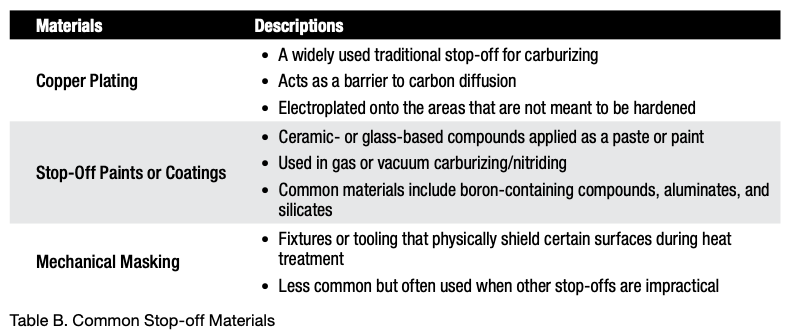
A material that masks the surface of steel and delays or prevents case hardening is called a stop-off or maskant. These materials are applied to specific areas of a steel part to prevent the diffusion of hardening elements (like carbon or nitrogen) into the surface during case hardening processes, such as carburizing, nitriding, or carbonitriding. (See Table B.)
Enriching Gas Additions (Sooting)
During the carburizing or carbonitriding process, it is not uncommon to develop a layer of soot on the surface of the parts, especially if the enriching gas additions begin before the entire load is uniformly up to temperature. In some instances, the amount of soot formation is such that the case depth or uniformity is affected. This is often difficult to diagnose, as the soot layer “washes off” during quenching in a liquid, and the part surfaces come out of the furnace looking reasonably clean.
Material-Related Issues
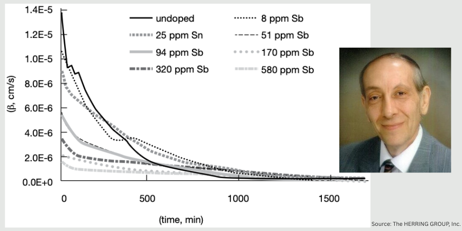
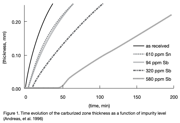
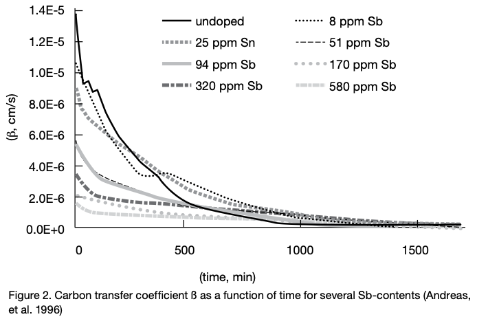
The use of scrap in steelmaking, especially for low alloy case hardening steels can lead to a relatively high level of impurities and tramp elements. At high temperatures these impurities tend to segregate at grain boundaries and migrate toward the surface. This type of segregation can retard case hardening by impeding element (e.g., carbon) transfer. For example, the effects of tin (Sn) and antimony (Sb) on the kinetics of carburization are particularly problematic (Figure 1).
The effect of tramp elements on retardation of carburization can be expressed in the following order (Andreas, et al. 1996), namely Sb > Sn > P > Cu > Pb. To see the effect of one such element, the carbon transfer coefficient (ß) for typical commercial steels is shown as a function of antimony (Sb) content (Figure 2).
In Summary
These are a few of the many causes delaying or preventing case hardening from being effective. There are many others, including alkaline cleaning compounds (in too high a concentration) and even phosphate and other drawing lubricants used in the manufacture of fasteners. Inspection and cleaning of the part surface prior to case hardening will avoid many of these issues. Reviewing material certification sheets for elements known to interfere with case hardening is also an effective way to anticipate problems with case hardening.
References
Herring, Daniel H. 2014. Atmosphere Heat Treatment, Volume 1. Troy, MI: BNP Media.
Herring, Daniel H. 2015. Atmosphere Heat Treatment, Volume 2. Troy, MI: BNP Media.
Ruck, Andreas, Monceau, Daniel, and Grabke, Hans Jürgen. 1996. “Effects of Tramp Elements Cu, P, Pb, Sb, and Sn on the Kinetics of Carburization of Case Hardened Steels.” Steel Research 67 (6): 242–48.
About the Author
Dan Herring “The Heat Treat Doctor” The HERRING GROUP, Inc.
Dan Herring has been in the industry for over 50 years and has gained vast experience in fields that include materials science, engineering, metallurgy, new product research, and many other areas. He is the author of six books and over 700 technical articles.
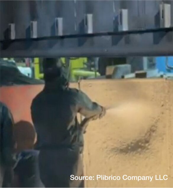
When it comes to furnace linings, most heat treaters focus on the hot-face materials, the heavy-duty refractories taking the brunt of molten metal, corrosive slags, and extreme heat. And just behind that armor lies a quiet defender: the refractory insulation layer. This layer is often the last line of defense between a functioning furnace and a costly, catastrophic failure. In this Technical Tuesday installment, Roger M. Smith, director of technical services for Plibrico Company, LLC helps readers understand the valuable role of refractory insulation for thermal stability.
Refractory insulation is more than a buffer or a back-up. It provides structural support to the working lining, maintains shell temperatures within safe limits, and cushions the entire structure against the stresses of expansion and contraction. When this layer fails, you don’t just lose insulation, you risk cracks, shell overheating, and lining collapse. In other words, it can turn a maintenance project into a full-blown emergency.
The Strength Factor: Why Compressive Strength Counts
If there’s one property that deserves special attention, it’s compressive strength. The insulation layer is like the foundation of a house: if it cannot support the load above it, the whole structure suffers. Insufficient compressive strength can lead to creeping, crushing, and distortion, all of which compromise the stability of the hot-face refractory.
At green or ambient conditions, most types of insulating refractories, including monolithic, mineral wool, and ceramic fiber boards, exhibit similar compressive resistance, typically in the range of 40−50 psi at 10% deformation, but strength changes significantly once the furnace heats up.
For example, most mineral wool and ceramic fiber boards contain organic binders that burn off at around 475°F, reducing their compressive strength by roughly 50% at furnace operating temperatures (based on the board manufacturer’s technical data sheets, see Table A). Over time, this can increase thermal conductivity through the reduced thickness of the insulating layer.
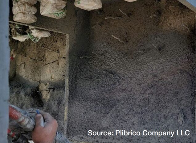
In contrast, monolithic lightweight insulating castables, like Plibrico’s Plicast Airlite 25 C/G, not only retain their compressive integrity as the temperatures rise, but they actually gain strength, according to ASTM C165 test data as the material fully sets and stabilizes under heat.
Figure 1. Monolithic insulation, gunned in place, stays strong and gains compressive strength during heat-up.
This difference matters: compressive strength is not static. It changes as the material heats up and insulating products that hold their strength at service temperatures provide a more stable, safe, and reliable support for the hot-face lining.
The takeaway? Stronger, more stable insulation is not just filler. It’s an active structural layer that helps prevent hot-face sagging, cracking, and premature failure, directly contributing to longer furnace life.
Thermal Stability: More Than Just Heat Resistance
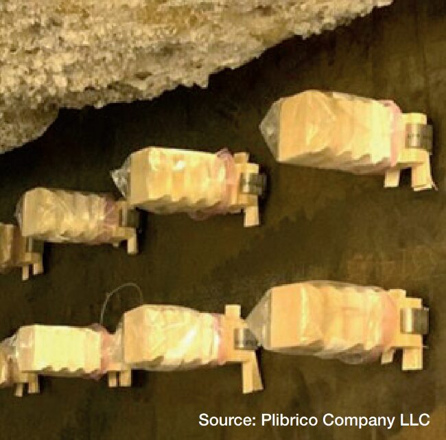
Figure 2. Confirmed anchor layout and fully prepped furnace wall ready for monolithic insulation installation.
Compressive strength plays a direct role in thermal stability. Denser, stronger castables with lower porosity are far better at resisting gas penetration, chemical attack, and erosion than lightweight, weaker alternatives.
When insulation loses stability, it can create voids, cracks, and hot spots, risks that threaten not only the hot-face layer but the furnace shell itself. This is why density and porosity are critical: denser insulating castables maintain their structure under load, resist infiltration, and provide reliable support for the hot face.
By contrast, mineral wool and board products often weaken as their organic binders burn off at service temperatures, leading to deformation and unpredictable thermal gradients.
Monolithic lightweight insulating castables can offer a more robust alternative. They retain their integrity as temperatures climb and can even gain compressive strength as they fully set and sinter during heat-up. This added stability reinforces the hot-face layer and helps prevent failures during thermal cycling.
There’s another layer to this: long-term thermal cycling. Furnaces rarely stay at one steady temperature; they ramp up, cool down, and undergo countless micro-cycles during operation. Insulation that can absorb these changes without cracking or delaminating is critical for avoiding premature lining failures.
In short, thermal stability is structural stability — the better your insulation performs under heat and cycling, the longer your furnace lining will last.
Designing for Expansion: Building Flexibility Into the System
Here’s where many lining failures start: in the different layers of lining expanding at different rates.
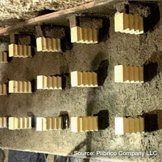
Figure 3. Completed furnace wall insulation
installation, finished in half the time required for board installation.
Hot-face refractories, often dense high-alumina castables, have significantly different thermal expansion coefficients compared to the lighter, more porous insulating castables behind them. The hot face may swell aggressively under load, while the insulation expands far less. If those differences are not accounted for, the result is tensile stresses, delamination, and cracking at the interface between layers. Over time, those cracks can grow, creating pathways for heat and corrosive agents to reach deeper into the lining.
This is where thoughtful design makes all the difference:
Anchor systems must hold both layers securely but flexibly, allowing each to expand without transferring destructive stresses. Using materials like monolithic refractories adds another advantage: their insulating properties help better protect the base of refractory anchors, reducing localized heat buildup and minimizing stress concentrations that can lead to cracking or premature anchor failure.
Installation sequencing should avoid locking the hot-face layer too tightly to the insulation, preventing “shear failure” during heat-up.
Layer composition must be selected so the expansion mismatch is minimized, balancing mechanical stability with thermal shock resistance.
When expansion is designed for, rather than ignored, the entire lining behaves like a single, flexible system instead of two incompatible parts competing for space.
Practical Tips for Getting It Right
Prioritize compressive strength. Choose insulation with enough strength to support the hot-face lining under load. Materials like monolithic lightweight insulating castables maintain or even increase compressive integrity at service temperatures, improving overall lining stability.
Figure 4. Gunned to the ideal thickness, insulation built with compressive strength can handle stress, prevent cracking, and maintain shape under heat.
Pick the right material for the zone. Not every insulating castable is created equal. Match density, chemistry, and expansion to the application.
Control the install. Low-water mixes, vibration placement, and proper curing are non-negotiables if you want consistent density and strength.
Don’t skip the heat-up schedule. Rushing dry-out or startup is one of the fastest ways to ruin a lining before it is even in service.
Revisit your anchor design and how you install around it. Poorly designed anchor layouts can lead to stress points and premature lining failures, so reviewing and optimizing the design is one of the cheapest ways to prevent costly mechanical issues. Plus, consider the installation method: board insulation requires time-consuming cutting and fitting around each anchor, while monolithic insulating refractories like Plicast Airlite 25 C/G can be installed around anchors in less than half the time, reducing labor while improving performance.
Built to Last
Insulation is not just about slowing heat loss, it is also about standing firm when your furnace is under its heaviest load. The right refractory insulation, engineered with compressive strength as a priority, gives your lining the backbone to absorb mechanical stresses, resist cracking, and maintain its shape through the punishing cycles of heat-up and cool-down. It does not just protect the shell; it supports the hot face, prevents hot spots, and preserves the entire system’s structural integrity.
3rd Party Test Lab – Orton Labs ASTM C165 Measuring Compressive Properties of Thermal Insulations
Note: Mineral Wool and Ceramic Fiber Boards contain organic binders that burn off by 475ºF. This reduces the strength of the board by 50% along with decreasing other important properties including thermal conductivity. Table A. Compressive strength at service temperatures: comparison of compressive resistance (10% deformation) between monolithic insulation lightweight castable/gunite materials such as Plibrico’s Plicast Airlite 25 C/G and mineral wool and ceramic fiber boards at increasing temperatures.
Choosing monolithic insulating castables that gain strength at operating temperatures, instead of mineral wool or ceramic fiber boards that lose half their capacity as binders burn away, is an investment in lining longevity. Get this layer right, and you secure longer campaigns, lower maintenance costs, and the confidence that your furnace can keep pace with production demands. Get it wrong, and you risk premature failures, costly outages, and avoidable downtime. In the end, refractory insulation built for compressive strength and stability is not just a detail, it is what keeps your furnace, and your operation, running at its best.
About The Author:
Roger Smith Director, Technical Services Plibrico
Roger Smith is a seasoned professional in the refractory industry. With Master of Science in Ceramic Engineering from the University of Missouri – Rolla, Roger has over 15 years of experience in the processing, development, and quality assurance of both traditional and advanced ceramics. He has a proven track record in developing innovative ceramic formulations, scaling up processes for commercial production, and optimizing manufacturing operations.
What are the ways to improve the cleaning process of component parts and reduce smoke from residue and environmental impact? Mercury Marine faced this challenge head on with a new system. Learn more about their solution in today’s Technical Tuesday case study written by Chris Tivnan the sales manager for North America at SAFECHEM North America Inc.
This informative piece was first released inHeat Treat Today’sAugust’s 2025 Annual Automotive Heat Treating print edition.
Mercury Marine’s Need for Clean
Mercury Marine is a world leading manufacturer of marine propulsion systems headquartered in Fond du Lac, Wisconsin. A subsidiary of Brunswick Corporation, Mercury Marine designs, manufactures, and distributes engines, services, and parts for recreational, commercial, and government marine applications.
Mercury Marine has an in-house heat treatment facility for the components they manufacture. These components include gear case parts, such as propeller shafts, pinions, forward and reserve gears, and clutches. The parts undergo typical manufacturing steps like turning, milling, or gear tooth generation. Some machines allow for dry cutting, while others involve hydraulic oil. In total, more than 170 distinct metal parts require cleaning before undergoing vacuum carburizing, hardening, tempering, and/or cryogenic treatments.
Carburizing with Closed-Vacuum Solvent Cleaning
But vacuum carburizing has not always been the technology of choice for Mercury Maine. Prior to 2023, parts and components underwent initial cleaning in an aqueous washer before proceeding to atmospheric carburizing. Then, they were quenched in oil and then underwent another round of cleaning with a water-based cleaner.
Figure 1. NANO vacuum carburizing system from ECM
Mercury Marine made the strategic decision to transition from atmospheric carburizing to vacuum carburizing in 2023. The shift was motivated by concerns related to smoke and environmental impact, particularly the evaporation of oil residuals during tempering. The desire for an overall environmentally friendlier process further fueled this change.
Vacuum carburizing benefits from more stringent cleanliness requirements on parts whereby all residue oils, greases, and debris must be removed entirely to prevent contamination of the furnace and the vacuum pump system. As a result of these considerations, Mercury Marine replaced their existing aqueous cleaning process with solvent-based cleaning, convinced that this solution provided superior and consistently reliable cleaning results.
Figure 4. With lipophilic and hydrophilic properties, DOWCLENE™* 1601 removes oils and greases just as effectively as certain polar contaminants like cooling emulsions or solids (e.g., particles and abrasives). Source: ECM USA
Their furnace equipment manufacturer ECM recommended a closed-vacuum solvent-based cleaning machine (Model: SOLVACS 3S) from the manufacturer HEMO. This design could be seamlessly integrated into their NANO vacuum carburizing system.
The vacuum cleaning machine runs on the modified alcohol solvent DOWCLENE™* 1601. Because of its lipophilic and hydrophilic properties, DOWCLENE 1601 can remove oils and greases just as effectively as certain polar contaminants like cooling emulsions or solids (e.g., particles and abrasives). The solvent also has low toxicity and good biodegradability.
Enabling High Environmental and Safety Standards
The switch from aqueous to solvent cleaning initially raised some safety concerns within Mercury Marine’s environmental safety committee. However, these concerns were swiftly addressed once the committee understood the operation of a closed vacuum cleaning machine and how it contributes to the highest safety and sustainability standards.
First, the airtight design of the machine virtually eliminates air emissions. The hermetically sealed construction means there is minimal risk of contaminating groundwater. Additionally, full machine automation removes operator handling and minimizes chemical contact.
Figure 2. While closed vacuum cleaning machines enable high-quality cleaning results with strong safety and sustainability standards, HEMO designs integrate seamlessly into furnace lines
Second, the machine’s built-in distillation unit enables continuous solvent recovery — as high as 95% in Mercury Marine’s case — thereby significantly reducing chemical consumption and waste while lowering overall cleaning costs. Distillation ensures that parts are consistently cleaned in fresh solvent. The effective cleaning result is further warranted by the high solvent quality in the rinsing step, followed by vapor degreasing as the last cleaning step, which is highly effective due to high temperature difference between parts and vapor. With the drying process below 0.1 psi, a perfect drying of the parts is guaranteed.
Additionally, unlike aqueous cleaning, solvent cleaning does not consume significant water, nor does it require wastewater treatment, providing a considerable cost and environmental advantage.
Using a simple test kit, solvent conditions can be easily monitored on a regular basis. Solvent lifespan can also be extended by adding stabilizers, reducing the need for frequent bath exchanges. Due to the high stability of the cleaner, only minimal stabilizer additions have been required since the machine was first put into operation.
Leveraging CFC for Solvent Cleaning
Another crucial factor supporting solvent cleaning is the use of carbon fiber composite (CFC) workload trays and fixturing of the heat treat batch in the cleaning machine. After cleaning the parts, the CFC fixtures are directly transferred into the vacuum furnace. This streamlined workflow eliminates the need to transfer parts between different fixtures, minimizing part damage or contamination while saving time. The durability and thermal stability of CFC fixtures make them ideal for such demanding applications.
Figure 3. Industrial robots streamline the loading and unloading of components in ECM’s vacuum furnaces and facilitate part transfers between systems, ensuring a fully automated heat treatment line
Since CFC is a highly absorbent material, it can soak up liquids during the cleaning process. Any remaining residue in CFC fixtures can be released during a vacuum heat treatment process, contaminating the oven, which will impact the process and cause improper heat treatment outcomes. Unlike aqueous cleaning, which leaves some liquids behind, solvent cleaning under vacuum conditions effectively removes these absorbed residues.
Additionally, CFC fixtures must be properly dried and moisture-free before entering the vacuum furnace. Moisture can lead to contamination, inefficient carburizing, oxidation, or vacuum system problems. Solvents dry much faster than water, mitigating the risk of water vapor migration into the vacuum carburizing system.
Superior Controllability and Quality Results
Since transitioning from atmospheric to vacuum carburizing, Mercury Marine has experienced many benefits due to a significantly more consistent and repeatable heat treatment process.
It is known that residual oxygen within the furnace atmosphere can react with alloying elements on the component’s surface. This interaction can lead to the formation of an oxidation layer, potentially affecting the compressive stress profile. Such layers need to be ground off. However, with vacuum carburization, these intergranular oxidations (IGO) no longer occur.
The vacuum carburizing process follows a precise “boost and diffuse” cycle, where the presence of carbon is transferred via acetylene. This approach provides superior controllability compared to atmospheric carburizing, where natural gas is used. Additionally, the absence of open flames and the energy-efficient design contribute to reduced greenhouse gas emissions.
In the past, Mercury Marine faced cleaning challenges following oil quenching. While maintaining clean quench oil is essential, frequent oil changes can be costly. When the quench oil was not cleaned frequently enough, deposits adhered to parts, especially drive shafts with spiral oil grooves for passage. Despite attempts at aqueous cleaning, such debris could persist, and additional blasting was needed to remove them.
Vacuum carburizing has eliminated this problem as the parts now undergo gas quenching instead of oil quenching, removing the aqueous cleaning step altogether.
The investment in a new furnace system, along with the integrated closed vacuum solvent cleaning machine, has proven highly beneficial. The fully automated system ensures that technicians are not manually handling baskets, while parts are cleaned to the highest standard, enabling a seamless vacuum carburizing process. Mercury Marine has expressed great satisfaction with the results, recognizing the system as a valuable addition to their manufacturing operations.
About The Author:
Chris Tivnan Sales Manager North America SAFECHEM North America Inc.
With two decades of experience in the chemical industry, Chris assists manufacturers in determining the right choice of cleaning agent and their parts cleaning operation. He also manages relationships with regional distributors as well as local OEMs/OEAs.
This Technical Tuesday installment is part of the Maintenance Message column series. In today’s edition Nate Sroka, quality assurance engineer for Ipsen, provides a complete maintenance guide to rebricking and relining atmospheric furnaces.Keep this one bookmarked for a quick reference to components, the rebricking process, expectations, and project timeline questions!
This informative piece was first released in Heat TreatToday’sAugust 2025 Automotive Heat Treating print edition.
Introduction
The interior brick walls of an atmosphere furnace endure extreme temperatures — sometimes reaching 2200°F — every hour of every day. Over time, the bricks become brittle, crack, and experience thermal expansion, which can open seams in the mortar.
After years of continuous operation, users may notice exterior walls becoming hot enough to melt insulated cables or components attached to the furnace. When bricks start falling out of place or insulation begins to sag, it’s time to shut down the furnace, assess damage, and plan for repairs. Typically, furnaces operating for five to ten years since installation or their last major overhaul require rebricking or relining.
Understanding the Components: Bricks and Boards
Knowing the key components used in the rebricking and relining process prepares you for discussions about repairs.
Insulated Fire Bricks (IFB) come in various temperature ratings. A 2300°F brick is less efficient and durable under extreme heat than a 2600°F brick but is often more cost-effective. High-rated bricks typically line the interior, while lower-rated bricks provide an additional insulation layer.
Insulating boards made from calcium silicate form the thermal barrier between the heating chamber and external components. They can withstand temperatures from 1000°F to 1800°F and are commonly used in lower-temperature furnaces.
Mineral wool is a fibrous insulating material used to fill gaps around furnace entry points and seams. Made from volcanic rock, ceramic, or slag, it allows for expansion and contraction due to temperature changes.
One key thing to know about atmosphere furnaces is that they are almost always “on.” In a vacuum furnace, recipes use electric elements that shut off after every cycle, and quenching often happens within the same chamber. However, in an atmosphere furnace, turning off the burners and then restarting the furnace from room temperature the next day is much less energy efficient than running the burners and holding a consistent temperature, even when the furnace is empty. Parts from an atmosphere furnace are typically quenched in an oil or salt bath, separate from the heating chamber.
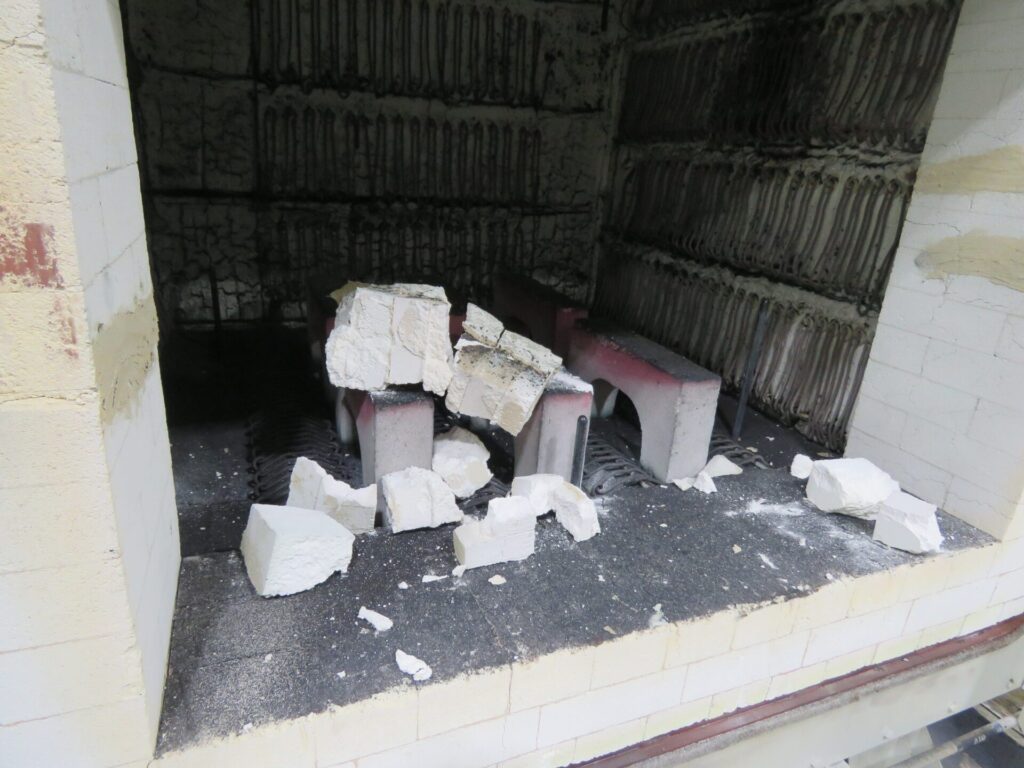
Figure 1. Debris from a damaged atmosphere furnace that collapsed on a hearth Source: Ipsen
Starting the Rebricking Process: What You Need to Know
Prepare for a Quote
First, review the pre-quote checklist to make sure you have the right information to get an accurate quote.
Pre-Quote Checklist: Important information to have on hand when getting a quote for rebricking or relining your atmosphere furnace
Furnace model number and serial number
Heating chamber dimensions (w/d/h)
Archway dimensions from base to top
Door dimensions and condition
Drawings or engineering plans outlining any aftermarket modifications
Typical operating temperatures
Any additional materials installed to prevent heat penetration
Photos from as many angles of the furnace as possible
A list of any consumable or heavy-wear components that also need to be replaced
Build a Timeline
Start collecting quotes at least a year in advance and place a purchase order no less than six months before the planned shutdown.
Consider Scheduling Factors
Many furnace operators are looking to have work like this completed during a summer or winter holiday shutdown period. Advanced planning improves scheduling flexibility.
Site Preparations
Before the service team arrives, ensure the workspace is ready:
Clear space for staging new materials and removing old bricks.
Provide access to a forklift, a durable waste collection container, a dumpster, and other required tools and resources.
Confirm power connections near the site for welding and other power tools.
Review lockout/tagout procedures with maintenance and operations teams.
Determine the required furnace cool-down time before disassembly and plan furnace shutdown accordingly.
Identify and disconnect any electrical, process gas, or water-cooling lines as outlined prior to service.
Rebricking Day: What You Should Expect
During disassembly, consider performing additional maintenance, such as:
Inspecting and rotating or replacing burner tubes
Inspecting and replacing pusher chains and skid hearth section
Checking doors, door hoods, and fan bungs
Conducting leak tests and changing the quench oil
Coordinate these tasks with the service team to avoid disruptions. The rebricking process spans several days, allowing time for concurrent inspections and repairs.
Final Inspection and Testing
Upon project completion:
Figure 2. A newly installed furnace, bricks properly installed, before furnace ignition Source: Ipsen
Inspect the furnace with the installation team to ensure all work aligns with project specifications.
Document any changes as a reference for future maintenance.
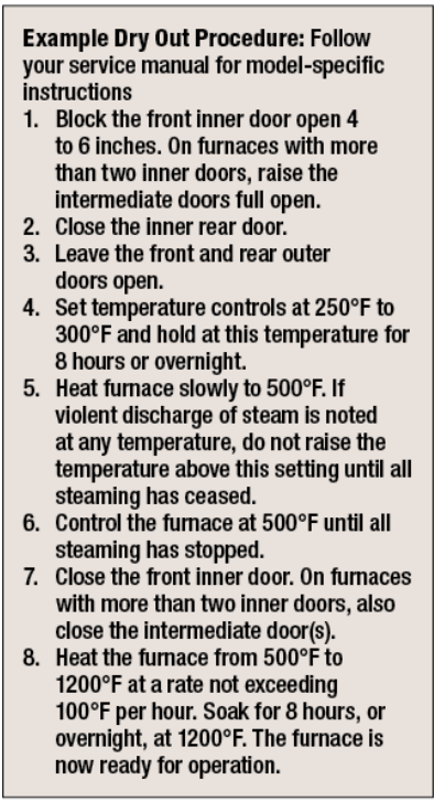
Perform a “dry out” procedure and clean the quench tank before refilling the tank. See “Example Dry Out Procedure” break-out box.
Run the furnace without parts to test for temperature uniformity.
Carburizing furnaces may need extra burn-in time to “season” the bricks:
Fresh bricks absorb free carbon until fully saturated.
When bricks are properly saturated, furnace atmospheres stabilize.
Time of burn-in is dependent on the percentage of carbon-level the system needs to achieve.
Identify potential hot or cold spots that may require further insulation adjustments.
Post-Installation Best Practices
A rebrick or reline of a furnace is a significant investment. To get the most from your furnace, make the time to take a proactive approach:
Establish a daily maintenance inspection for the first week, followed by weekly checks for the first month.
Resume regular maintenance schedules if no issues arise.
Schedule independent inspections with a field service engineer at three, five, seven, and nine years to proactively assess furnace condition and secure preferred maintenance dates.
By following these steps, atmosphere furnace operators can maximize uptime, streamline service quoting, optimize downtime usage, and ensure efficient future rebuilds.
This article was originally published on ipsenusa.com.
About The Author:
Nate Sroka Quality Assurance Engineer Ipsen
Nate Sroka has been with Ipsen since March 2014. He holds a bachelor’s degree in mechanical engineering and a master’s degree in engineering and industrial management from Northern Illinois University. Nate oversees the Quality/Documentation/Warranty (QDW) department, ensuring that Ipsen maintains ISO 9001 and ISO/IEC 17025 standards. He is also responsible for documentation related to installation and operations manuals, regulatory certificates, and managing warranty programs.
For more information: Contact Nate Sroka at nate.sroka@ipsenusa.com.
The Heat Treat Doctor® has returned to offer sage advice to Heat Treat Today readers and to answer your questions about heat treating, brazing, sintering, and other types of thermal treatments as well as questions on metallurgy, equipment, and process-related issues.
This informative piece was first released in Heat Treat Today’sAugust 2025 Automotive Heat Treating print edition.
Quench cracking during heat treatment can turn expensive components into scrap metal in seconds. In today’s Technical Tuesday article, Dan Herring (The Heat Treat Doctor®) explores more about the underlying mechanisms and proper preventative measures to save you time, money, and ensure reliable part performance.
As a young heat treater, I learned first-hand about quench cracking while running various dies for our tool and die shop — and succeeded in cracking all of them! I have never forgotten the foreman’s (rather animated) critique of my heat treating abilities. Quench cracking can be a significant problem for heat treaters, its potential consequences ranging from costly rework to premature failure in the field. Let’s learn more.
We must not only understand the mechanisms involved but also take proactive steps to avoid it. This includes careful consideration of such items as:
Material (e.g., chemistry, hardenability, form, mill processing)
Component part design (e.g., sharp radii, thin and thick sections next to one another)
Manufacturing processing steps (e.g., the effect of stress relief after rough machining)
Part loading (e.g., part orientation in relation to the quench, fixturing, total load weight)
Equipment choice (i.e., limitations and capabilities)
Quench medium (e.g., type, agitation, flow characteristics, temperature, temperature rise)
Process parameters (e.g., ramp rates, atmospheres, vacuum levels)
The Heat Treatment Challenge
Quench cracking primarily occurs during the hardening process, typically when materials are rapidly cooled via quenching. Since the cooling process introduces internal stresses within the material, it can result in crack formation. These stresses are a result of the rapid transformation of the material’s microstructure, most notably when transforming to martensite, a very hard, brittle structure.
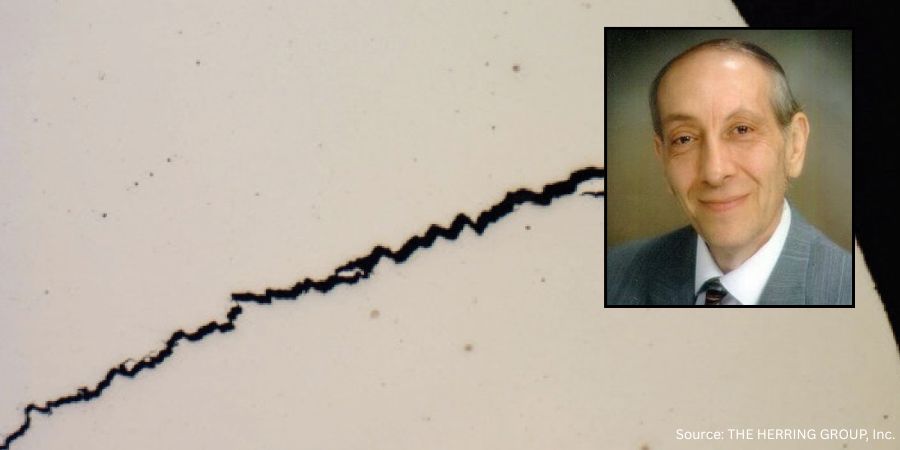
Figure 1. Quench crack in a 4140 axle shaft
Mechanisms Involved
Failure mechanisms related to quench cracking include the following seven factors.
Material Imperfections
As material is heated, thermally induced stresses can cause existing surface or subsurface defects, such as inclusions, laps, and seams. These defects act as stress risers to open and propagate into cracks. Once a defect reaches “critical flaw size” — the smallest flaw that can lead to failure under expected operational stress levels — crack propagation will begin and lead to part failure.
Rapid or uneven heating only exacerbates this issue, especially when a material undergoes phase transformations that introduce volumetric changes.
Stress Risers
Sharp corners, steep edges around holes, and even grooves in parts create stress concentration points where quench cracking is most likely to occur. These features also result in localized heating and cooling, causing differential stresses that can initiate cracks.
The sharp edges of a part, for instance, cool much faster than the rest of the material, leading to a high risk of cracking.
Proper design modifications, such as adding radii to sharp corners, can reduce the likelihood of stress concentrations.
Rapid Cooling and Phase Transformation
The transformation from austenite to martensite during quenching is a key contributor to internal stresses. The rate at which the material cools can greatly influence these stresses. If cooling is too rapid or if tempering is delayed, the material can become overly brittle, leading to quench cracking.
Improper Heating and Overheating
Overheating during the austenitizing process can lead to coarse-grained structures that are more prone to quench cracking. Coarse grains increase the depth of hardening but reduce the material’s resistance to cracking. It is critical to avoid temperature overshoot, high ramp rates, and excessively long dwell times when heating.
Inadequate Quenching Methods
The choice of quench medium (brine, water, oil, polymer, high pressure gas, etc.) can also contribute to quench cracking. Overly aggressive quenchants may create excessive thermal stresses.
Improper Fixturing
The way parts are positioned during quenching can create problems. If parts are bunched together in a basket, uneven cooling rates will occur, with parts on the edges cooling faster than those in the center. This can lead to differential stresses and increase the risk of cracking.
Delays Between Quenching and Tempering
Quenching produces high residual stresses in the material, and if parts are not tempered soon after quenching, these stresses can lead to cracking. For materials with high hardenability, such as 4340 steel, immediate tempering (usually within 15 minutes of quenching) is critical to prevent in-service failure.
Understanding Fracture Mechanics
Contact us with your Reader Feedback!
Understanding these mechanisms is critically important. A material’s fracture toughness, which is the ability to resist crack growth, is defined by the stress intensity factor (KIC). This value varies based on the material’s properties and the size and geometry of the crack. The important point to remember is that when the applied stress reaches a critical threshold, cracks begin to propagate (literally at the speed of sound), leading to catastrophic failure.
Digging a bit deeper, there are three primary modes of fracture:
Tensile (Mode I): Fracture caused by tensile stress at the crack tip.
Sliding (Mode II): Fracture caused by shear stress that causes the two sides of the crack to slide.
Tearing (Mode III): Fracture caused by shear forces in a direction perpendicular to the crack plane.
Preventive Measures
Several strategies can be employed to minimize the risk of quench cracking during heat treatment. They broadly fall into the following categories.
Material Selection
Choosing the right material for the job is essential. Many designers select materials with high hardenability, forgetting that they can be prone to cracking. Additionally, one should take special care with materials that have high carbon content or are heavily alloyed.
Design Considerations
Ensure that part designs minimize stress risers. Avoid sharp corners and incorporate radii where necessary. Proper design can reduce the likelihood of cracks forming at critical locations.
Improved Manufacturing Practices
Proper stock removal during machining and addressing surface imperfections before heat treatment can prevent the initiation of cracks. Machining should aim to eliminate any seams or inclusions that might act as nucleation sites for cracks. Stress relief after rough machining is almost always a good idea.
Control of Heat Treatment Parameters
Maintain tight control over the heating and quenching processes to ensure uniformity. Avoid overheating and try to ensure that the part enters the quench medium in the best possible orientation to reduce the likelihood of creating differential cooling rates.
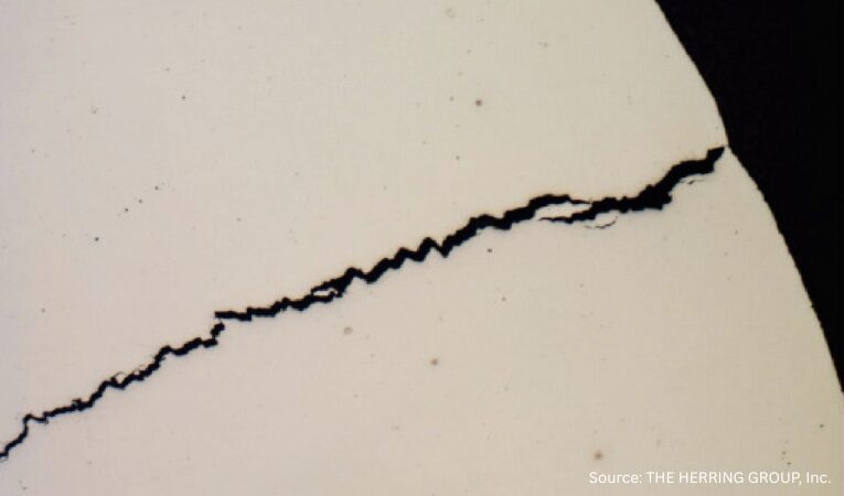
Figure 2. Quench crack due to a combination of rapid heating, overheating and improper
polymer quench medium concentration in a motor shaft (50x, as polished)
Quenching Media
Select the appropriate quenching medium based on the material, part geometry, and load. Less aggressive quenchants or minimizing time in the quench should be considered for materials with moderate to high hardenability.
Post-Quench Tempering
Temper parts as soon as practical after quenching to avoid concerns with internal stresses. High-hardness materials should be tempered immediately to prevent quench cracking.
Quench Cracking in Other Materials
Quench cracking is not exclusive to steel. Other materials, such as nickel and cobalt superalloys, can also experience cracking due to similar mechanisms. In these materials, the phenomena are often referred to as “fire cracking,” “strain-age cracking,” or “stress cracking.” As with steel, cracks in these materials are often linked to high residual tensile stresses on the surface and the presence of stress raisers. Strategies, such as shot peening, redesigning part geometries, and improving surface finishes, can help mitigate cracking in superalloys.
Summing Up
Quench cracking represents a significant challenge in heat treatment, but by understanding its underlying mechanisms, heat treaters and engineers can take steps to mitigate the risk. Material selection, part design, proper heat treatment procedures, and timely tempering are all critical factors in preventing quench cracking and ensuring the integrity of components. A proactive approach to addressing flaws and stress concentrators combined with careful attention to detail in every stage of the manufacturing and heat treatment process can greatly reduce the likelihood of failure and contribute to the long-term success of heat treated products.
References
Herring, Daniel H. 2012. “Quench Cracking.” Industrial Heating, April.
Herring, Daniel H. 2015. Atmosphere Heat Treatment, Volume 2. BNP Media.
Johnson, D. D. 2005. “Thermal and Mechanical Behavior of Materials.” University of Illinois.
Klarstrom, Dwaine L. 1996. “Heat Treat Cracking of Superalloys.” Advanced Materials and Processes, April.
Krauss, George. 2005. Steels: Processing, Structure and Performance. ASM International.
About the Author
Dan Herring “The Heat Treat Doctor” The HERRING GROUP, Inc.
Dan Herring has been in the industry for over 50 years and has gained vast experience in fields that include materials science, engineering, metallurgy, new product research, and many other areas. He is the author of six books and over 700 technical articles.
Whether you need insight on enhancing your energy utilization, managing induction systems (troubleshooting), or prolonging equipment longevity, today’s Technical Tuesday original content feature will keep you well-informed.
Heat TreatToday has coalesced technical information across articles from key experts, including tips to improve your energy efficiency, a walk-through guide for troubleshooting your induction system, and ten practical tips for improving your equipment longevity.
Induction and Sustainability Tips Part 2: Efficient Power
As energy efficiency becomes a driving force in modern heat treating, manufacturers are turning to smarter induction technologies to cut waste and lower costs. In this second installment of Heat Treat Today’s sustainability series, explore how AC-to-DC conversion, intelligent power feedback systems, and advanced diagnostics can transform your induction heating setup into a cleaner, more consistent, and cost-effective process.
“Furthermore, transformers operate at optimal efficiency when under a reduced load – i.e., less than 70% output in steady-state heating – rather than ramping up to the full operating temperature. Another advantage of the DC-type transformer is that its operating power factor is very close to 1.0, which lowers the utility company’s calculation of peak demand surcharges.”
Facing erratic heating, poor consistency, or unexpected shutdowns in your induction system? This comprehensive guide walks heat‑treat operators through a ten‑step diagnostic framework for identifying and resolving common induction issues.
Figure 2. Induction
system components Source: Contour Hardening, Inc.
“The induction process involves many characteristics such as: position of the piece within the induction coil, load positions, cooling positions, cycle times, applied electric power, and others. It is important that the professional can identify the failure and the particular situation at the moment in which it is occurring.
On some occasions, the failures are not evident and therefore it is essential to analyze the part that has been treated. This analysis can be key to understanding situations such as poor depth due to electrical power or decrease in output frequency, among other possible scenarios.”
New and Improved Tips for Induction Equipment Longevity
Heat treaters are always looking for ways to extend the life of their induction tools, but what methods are proven maintenance strategies? Focusing on the durability of coils, bus bars, inductors, and quench components, this technical article will give you practical and reliable tips to promote longevity in your equipment.
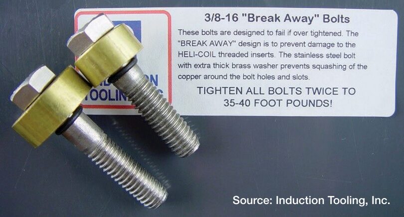
Figure 2. Break-Away bolts designed to fail beneath the washer if over tightened
“More than coils — When working to optimize the life of induction equipment, don’t focus solely on the coils. Bus bars, inductors, and quenching equipment are also key to success.
Austenitic stainless steel — Use austenitic stainless steel for fasteners, fittings, and hose clamps, and remember, non-ferrous is the way to go.
CNC machining — Manufacturing with a 5-axis CNC machine ensures quality and consistency.
“Break-Away” bolts — For fasteners, use “Break-Away” bolts on contact surfaces. These bolts are designed to fail beneath the washer if they are overtightened, a design that prevents damage to the threaded insert inside the copper contact.”
In this Technical Tuesday installment featuring Combustion Corner by Jim Roberts, president of U.S. Ignition, readers are enlightened about how upcoming policies might impact their burner systems, fuel mixtures, and equipment. Could certain policies impact technical requirements of heat treating? Find out more below.
This informative piece was first released inHeat Treat Today’sJuly 2025 Super Brands print edition.
A furnace guy goes into a bar and says, “This looks like a fast crowd… and all the players nod in agreement.”
Where are we? It’s the future! And in heat treating and combustion circles, the changes that will occur in the next several years will be very impactful to our industry. We’ve all heard these things, and we have some of the very best experts in the world working for us in this industry to make sure that we continue to grow and to be a leader in the legislation and rules that could cripple the wonderful world of heat treating and metals.
We are lucky to have industry associates at the Metal Treating Institute (MTI)who understand the impact of some of these new regulations. In this year’s Air & Atmosphere issue of Heat Treat Today magazine, Michael Mouilleseaux (Erie Steel LTD) provided updates on the proposed decarbonization initiatives. I have seen presentations by Michael and his committee composed of Heather Falcone (Cook Induction Heating Company) and Ben Gasbarre (Gasbarre Thermal Processing Systems). This is critical knowledge for us all, and we should be staying as vigilant and supportive as we can. Michael’s interview is a must-read in that February issue – if you missed it, go back and read it. Please.
And then you say, “What’s this got to do with combustion equipment and the stuff that this Roberts guy is normally talking about?”
Well, not only does the decarbonization mandate mean the possibility of costs through government burdens and penalties, but the equipment and process change requirements are going to be staggering if we don’t prepare.
As long as I’m in a name-dropping mood, I’m going to mention Brian Kelly of Honeywell. Brian is a degreed aerospace engineer, and yet he decided to come play in the mud with us furnace guys for a career. Brian has several detailed presentations online about some of the prime initiatives for all the combustion equipment companies — hydrogen Combustion. Yep, the “H” word. The holy grail of zero pollution. One of those presentations includes fascinating detailed data on hydrogen and other emission initiatives, given by Brian Kelly and Todd Ellerton on YouTube regarding future combustion technology requirements.
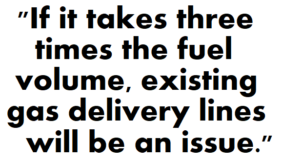
“So, what does the “three times faster” thing mean, Jim?”
Well, all major combustion equipment companies, like Honeywell, understand that hydrogen requires three times the amount of fuel to generate the same amount of available heat as natural gas. Hydrogen also burns with seven to eight times the “flame speed” of natural gas. It burns, on average, about 400 degrees hotter (F) than natural gas. And so, from an engineering standpoint, there are a fantastic number of variations that must be considered as we look forward, especially when addressing CO₂ and other emissions. Add propane, butane, methane, producer gas, landfill gas, and anything else that is presently being utilized in the heat treat circles, and that provides a lot of possible variations!
Now, it needs to be said that a good many burners can burn hydrogen already. The anticipation of this level of scientific and ecological requirements was seen a long time ago. Conversely, many cannot. Brian Kelly explains that 17% of the present pre-mix/blended fuel systems cannot utilize this fuel. It also bears mentioning that there are three different grades of hydrogen production levels.
So, let’s start doing the math on how many iterations it will take. But here is the biggest tidbit of hydrogen science in the combustion world – hydrogen is the smallest molecule and the lightest in a molecular sense. Helium is smaller and lighter, for fact-checker purposes, but we aren’t trying to burn helium, are we? So, as we blend hydrogen with our other fuels (i.e., the most practical way to maintain some of the infrastructure and equipment), we need to have our combination equipment suppliers test and verify that which exists will work.
Obviously, if it takes three times the fuel volume, existing gas delivery lines will be an issue. At the molecular level, smaller and lighter means that many existing seals, connections, and control valves may no longer be gas-tight and may leak. That’s not good! If the flame speed of these fuels is five to eight times that of existing fuels, temperature profiles within the process will need to be reviewed and re-calibrated. And if it burns 400 to 500 degrees hotter, certainly that will require a review of the former materials of construction.
So, how does this tie into the original theme of “The future is coming fast?” Well, we have just touched briefly on one possible fuel transition that is on the horizon. Carbon points/credits are already being taxed in Europe. We can bet that these global decarbonization efforts will be moving ahead. We will need a review so that a “head in the sand” mentality does not catch any of us in the thermal processing community flatfooted and ill-prepared.
It’s easy to think that it won’t affect you. When I mentioned “three times as fast,” of course, I was alluding to the fuel references, and the best way to be prepared for the future is to see it coming. Be alert and stay current, and we will adapt as an industry, as we have so many times before. Until next time …
About The Author:
Jim Roberts President US Ignition
Jim Roberts president at U.S. Ignition, began his 45-year career in the burner and heat recovery industry focused on heat treating specifically in 1979. He worked for and helped start up WB Combustion in Hales Corners, Wisconsin. In 1985 he joined Eclipse Engineering in Rockford, IL, specializing in heat treating-related combustion equipment/burners. Inducted into the American Gas Association’s Hall of Flame for service in training gas company field managers, Jim is a former president of MTI and has contributed to countless seminars on fuel reduction and combustion-related practices.
For more information: Contact Jim Roberts at jim@usignition.com.
The Heat Treat Doctor® has returned to offer sage advice to Heat Treat Today readers and to answer your questions about heat treating, brazing, sintering, and other types of thermal treatments as well as questions on metallurgy, equipment, and process-related issues.
Today’s Technical Tuesday is a pre-release foretaste of the great content you can find in Heat Treat Today’sJuly 2025 Super Brands print edition.
Heat treaters and metallurgists speak a language unique to our industry and it can be confusing at times; terms like intergranular oxidation (IGO) and intergranular attack (IGA) are good examples, as these terms are often (incorrectly) used interchangeably. While these two phenomena sound similar, they have distinct mechanisms, causes, and impacts on material properties. Expert Dan Herring explores them more below.
What is IGO?
Contact us with your Reader Feedback!
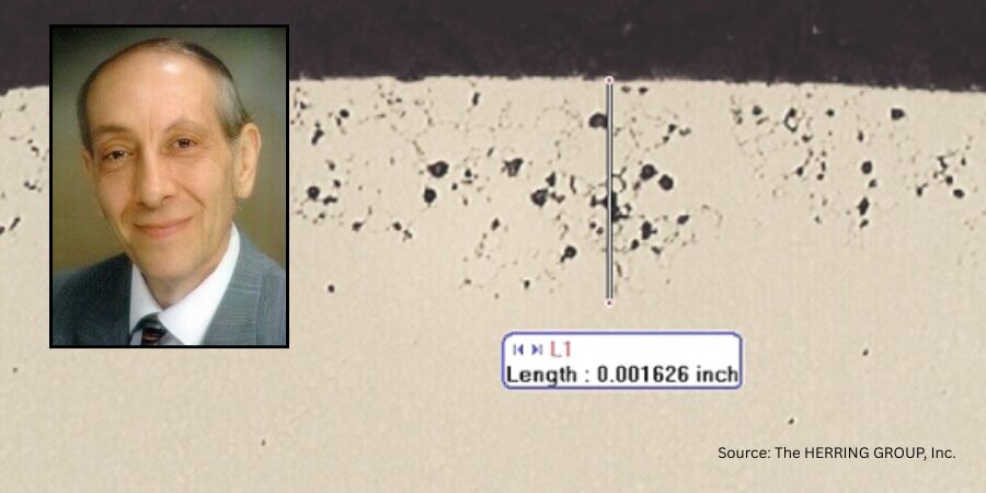
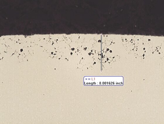
IGO is a process by which oxygen preferentially reacts with the metal surface at the grain boundaries, creating oxides (Figure 1). It is not uncommon, for example, to see IGO present after a hardening process run in an Endothermic or nitrogen/methanol atmosphere. As parts are heated to austenitizing temperature, oxygen present due to minute air leaks or produced during the various chemical reactions with the atmosphere results in IGO. The grain boundaries are highly susceptible to oxidation because these are areas where different crystallographic grains meet and are areas of high energy due to the atomic mismatch and disruption of the regular crystal lattice structure.
Figure 1. Intergranular oxidation (IGO) along the surface of a heat treated chromium steel component. 1000X – As Polished Source: The HERRING GROUP, Inc.
What is IGA?
Figure 2. Intergranular attack (IGA) along the surface of a martensitic steel component caused by excessive submersion time in a citric acid solution. 1000X – As Polished Source: The HERRING GROUP, Inc.
IGA, on the other hand, is a broader term that refers to a corrosion phenomenon (aka chemical attack) that specifically targets the grain boundaries of a material. Unlike IGO, intergranular attack (Figure 2) is not limited to oxidation reactions but encompasses a variety of forms of attack involving such things as the formation of precipitates, the dissolution of material at grain boundaries, or the creation of corrosion cracks. Common forms of IGA include stress corrosion cracking (SCC) or sensitization in stainless steel.
In stainless steels, IGA is often triggered by high-temperature environments, usually in the range of 840º – 1560ºF (450 – 850°C) where carbon reacts with chromium to form chromium carbides at the grain boundaries, thus reducing the material’s resistance to corrosion in localized regions. In other alloys, factors like pH, chloride concentration, and temperature can lead to IGA.
Both IGO and IGA weaken the material’s structural integrity or lead to embrittlement compromising the material’s integrity.
Effect on Material Properties
The main effect of intergranular oxidation is the degradation of the mechanical properties, particularly a reduction in both ductility and toughness. As oxidation progresses along the grain boundaries, the material tends to become brittle, which can lead to premature failure under certain types of stress or thermal cycling. IGO often appears visually as a uniform discoloration or thin oxide layer on the surface. Surface pitting is not typically observed.
By contrast, IGA often appears as visible cracks, pits, or localized regions where the metal has been attacked (along the grain boundaries). This leads to a reduction in mechanical strength and can lead to SCC under certain circumstances. IGA can severely compromise the integrity of the material, particularly in critical applications like pipelines, pressure vessels, and nuclear reactors.
Materials Involved
IGO is most commonly observed in steel, aluminum, titanium, and nickel-based alloys, not only during heat treatment but when exposed to oxidizing environments in high-temperature applications, which also result in degradation and loss of material strength and other properties.
IGA tends to be more prevalent in stainless steels, corrosion-resistant alloys, and aluminum alloys. It is especially noticeable in alloys that are susceptible to sensitization (where chromium carbides precipitate at grain boundaries), leading to localized corrosion and cracks. Alloys that form a passivating oxide layer can be more susceptible to IGA if that layer is disrupted.
Principal Concerns
The main concern with intergranular oxidation is material embrittlement, leading to reduced ductility and potential failure under mechanical stress, especially in high-temperature applications. It can also affect the integrity of critical components, such as those used in aerospace or power generation industries.
By contrast, the primary impact of intergranular attack is loss of material strength, leading to structural failure, often without any clear outward signs (e.g., under chloride-induced SCC). It is more likely to cause immediate failure or a dramatic loss in performance, especially in structures exposed to corrosive environments.
How to Detect IGO and IGA
IGO is typically detected by examining the material’s surface using optical or scanning electron microscopy (SEM). Non-destructive techniques, such as X-ray diffraction (XRD), can also be used.
IGA is usually detected through methods like microstructural examination, electrochemical testing, or failure analysis. Techniques, such as SEM or energy-dispersive X-ray spectroscopy (EDS), can be used to examine the grain boundary regions for signs of corrosion.
How to Avoid IGO and IGA
IGO can be avoided by one or more of the following:
Environmental control: Making sure the heat treat furnace has no leaks, reducing oxygen partial pressure or controlling the furnace atmosphere in high-temperature heat treat operations.
Alloy design: The use of materials with stable oxide-forming elements (e.g., chromium, titanium and aluminum) or alloys with high resistance to oxidation (e.g., nickel-based superalloys).
Temperature control: Maintaining lower process temperatures and shorter times where possible to prevent oxidation at the grain boundaries.
Coatings and surface treatments: Application of protective coatings, such as copper plating, post-heat treatment aluminizing, or chrome plating, to reduce oxygen interaction with the grain boundaries during service.
IGA can be avoided by one or more of the following:
Environmental control: Reducing exposure to aggressive chemicals (e.g., chloride ions) by maintaining proper pH levels or using inhibitors in post-cleaning processes.
Proper alloy selection: Selecting materials resistant to intergranular corrosion (e.g., low carbon “L” grades of stainless steel or alloys with improved grain boundary stability).
Heat treatment: Avoiding sensitization of stainless steel by proper heat treatment methods that prevent the formation of chromium carbides at grain boundaries.
Stress relief: Reducing the likelihood of stress corrosion cracking by managing internal stresses during manufacturing and in-service conditions.
Key Differences
The differences between these phenomena are summarized in Table 1.
Table 1. Key differences between IGO and IGA Source: The HERRING GROUP, Inc.
Summing Up
While both IGO and IGA involve attack at the grain boundaries, they differ in their mechanisms, causes, and effects. From a heat treater’s perspective, IGO most often results at high temperature in oxygen-bearing furnace atmospheres, while IGA often results from pre- or post-heat treatment processing (cleaning, passivation, plating, etc.). Proper material selection, furnace and environmental control, awareness of what can happen, and inspection for these effects are key to preventing them from occurring.
References
Roberge, Pierre R., Corrosion Engineering: Principles and Practice, Mc-Graw Hill LLC, 2008.
Stene, Einar S., Fundamentals of Corrosion: Mechanisms, Causes, and Monitoring.
Schweitzer, Philip A., Fundamentals of Corrosion: Mechanisms, Causes and Preventative Methods, CRC Press, 2009.
About the Author
Dan Herring “The Heat Treat Doctor” The HERRING GROUP, Inc.
Dan Herring has been in the industry for over 50 years and has gained vast experience in fields that include materials science, engineering, metallurgy, new product research, and many other areas. He is the author of six books and over 700 technical articles.
In this Technical Tuesday installment, Kazunori Hokaku, business director/general manager/sales engineering dept. at Tokai Konetsu Kogyo shares the sustainability benefits of SiC heating elements.
This informative piece was first released inHeat Treat Today’sMay 2025 Sustainable Heat Treat Technologies print edition.
In recent years, Silicon Carbide (SiC) heating elements have been increasingly used in demanding applications involving high temperatures and extreme atmospheres. Battery material manufacturing is one of many such applications. Therefore, improved service life contributes to increased productivity and sustainability as well as reduced industrial waste. This article discusses the long service life for recrystallized SiC heating elements having both excellent oxidation and corrosion resistance.
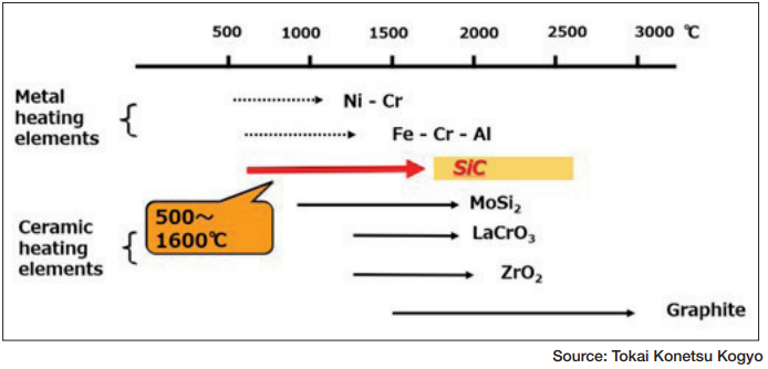
Tokai Konetsu Kogyo in Japan has been manufacturing EREMA® SiC heating elements since 1936. SiC heating elements are categorized as ceramic heating elements, which are widely used in a temperature range between 932°F–2912°F (500°C–1600°C) as shown in Figure 1.
Figure 1. Temperature range for heatingTable 1. Example of applications for SiC
heating elements
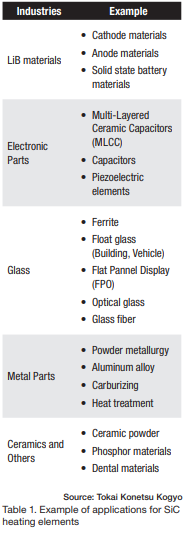
The heat value per unit area (i.e., watt density) of SiC heating elements is quite high, 5 to 10 times that of metallic Nichrome wire heating elements, for example. SiC heating elements are chemically stable and an environmentally friendly source, free of air and noise pollution compared to gas-fired or liquid fuel systems. As such, they are chosen and used for a variety of applications, such as Lithium-ion battery material (i.e., cathode/anode/solid state battery materials), powder metallurgy, aluminum, hardening and case hardening applications (e.g., carburizing), electronic parts (MLCC, ferrite), and dental materials as shown in Table 1.
SiC heating elements come in a variety of shapes, namely straight rod, U-shaped, and W-shaped designs. They are affordable and easy to handle compared to other ceramic heating elements. It is important to remember, however, that their service life is drastically influenced by high temperatures and the atmosphere.
The failure mechanism of a SiC heating element to its service life is shown in Figure 2. SiC reacts with O2 and creates SiO2, by which the resistance of the heating element increases.
Therefore, increasing bulk density and reducing specific surface area are key to service life longevity. This relationship between bulk density and service life in alkaline atmosphere (Li2CO3) has been explored by Tokai Konetsu Kogyo using scanning electron microscopy (SEM) photos with results as shown in Figure 3.
Figure 2. Mechanism of resistance increase (service life)
Silicon Carbide 101
■ Electric heating elements are a popular choice of many heat treaters. They come in a variety of shapes, sizes, and materials. One of the most common types are silicon carbide (SiC) heating elements, known by several tradenames including Globar™ and StarBar™. They are used extensively throughout the heat treating industry when high temperatures, maximum power, and heavy duty cycles are required.
A SiC heating element is typically, but not always, an extruded tubular rod or cylinder made from high purity grains of silicon carbide that are fused together by either a reaction bonding process or a recrystallization process at temperatures in excess of 3900°F (2150°C). The result is a chemically stable material with a low thermal expansion coefficient and little tendency to deform.
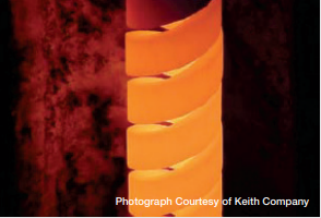
Spiral-cut silicon carbide heating element design provides increased resistance for applications up to 3000°F (1650°C)
Recrystallization forms fine grains of silicon carbide that act as “bridges” or connection points between larger grains thus forming conductive pathways. The number of bridges formed dictates the material’s resistance: the greater the number, the lower the resistance. The secret to the creation of a good heating element is controlling this formation process within the material to develop a consistent electrical resistance
The factors that influence the life of a SiC heating element include the type of furnace atmosphere, watt density, operating temperature, type of service (continuous or intermittent), and maintenance. Furnace type, design, and loading play an important role as well. SiC heating elements are extremely versatile operating, for example, in air up to 3000°F (1650°C).
Finally, the choice of heating element depends on many factors. For example, SiC heating elements are capable of higher operating temperatures and higher watt loadings than say metallic elements; they are self-supporting and can be used in furnaces either too wide or too long to be spanned by other element types and are relatively easy to change while hot. SiC heating elements are used extensively in brazing and sintering furnaces running continuously at or above 2050°F (1120°C) and for other processes where the temperature range lies between 2375°F (1300°C) and 2725°F (1500°C).
With permission from the author, Dan Herring, the information cited has been used in part from, Herring, Daniel H. “Electric Heating Elements Part One: Silicon Carbide.” Industrial Heating, September 2008. ■
SEM photos show the Sustainable Development Goals (SDGs) model observed increased bulk density with low porosity and very thick neck growth of SiC grains. The specific surface area for the SDGs model of 0.03 m2/g by Brunauer–Emmett–Teller (BET) method is smaller than that of the standard high-density grade of 0.05 m2/g.
Figure 3. Life test (resistance increase in alkaline atmosphere)
As a result, the graph in Figure 3 shows that the service life for the EREMA®SDGs model (BD = 2.65) is the longest, which means a reduction not only in downtime of furnace operation but also of industrial waste.
About The Author:
Kazunori Hokaku Business Director/General Manager/Sales Engineering Dept Tokai Konetsu Kogyo
Kazunori Hokaku graduated from Kyoto Institute of Technology in 1985 with a major in ceramics. He has been with Tokai Konetsu Kogyo Co., Ltd., since 1985 and is currently the business director/general manager/sales engineering dept.
By Steven Christopher, senior engineer at Super Systems Inc., and Katie Bastine, former quality manager at ThermoFusion.
The three letters, P-I-D, send shivers down most spines; tuning may induce an actual headache. This has proven true for decades, but why is the concept so overwhelming? This article will attempt to answer that difficult question with simple considerations.
This informative piece was first released inHeat Treat Today’sMay 2025 Sustainable Heat Treat Technologies print edition.
PIDs (Proportional-Integral-Derivative) need not be anxiety-producing. Let’s break it down to reduce the stress, but first, let’s credit one of the world’s deepest thinkers. Einstein defined insanity as, “Repeating the same thing over and over and expecting different results.”
Is this happening in our industry? Why does every Proportional-Integral-Derivative (PID) article begin with tuning a new controller? In reality, very few new controllers are installed. Instead, a failing TUS dictates re-tuning an existing controller. Let’s start with an existing controller, and then intentionally RUIN our PIDs.
Katie Bastine, quality manager of Nadcap-certified Thermo-Fusion of Hayward, CA, agreed to help and offered one of the company’s many Endothermic nitriding or batch furnaces. We settled on a vacuum furnace with graphite heating elements, which is a perfect candidate because it was relatively quick to respond and easy to manipulate.
What Are PIDs?
According to Blink author Malcolm Gladwell, we need a basic understanding of PIDs, and perhaps no more. His fantastic book details the brain’s ability to thin-slice situations — meaning the ability to make quick, often correct, decisions. He discusses in great depth the importance of data for experts, but he hypothesizes that too much data for the average person negatively influences the decision-making process. Gladwell claims, “The role of those other factors is so small … that extra information is more than useless. It’s harmful. It confuses the issues.”
This may be our mistake: too much information freezing our ability to act rather than empowering us. The goal of this article is not to train experts but rather to help with that often-paralyzing first step.
Consider the following definitions:
Proportional band (Pb) compares the error at a single moment or the difference between the set-point and control TC. Adjusting the Pb parameter determines how large an error is required to reduce/increase output.
Integral (or reset) compiles this same error over a period of time, appropriately adjusting to the Pb’s output.
Derivative (or rate) monitors the rate of change, estimating future error and “applying the brakes” when necessary. The remainder of this article limits theory and focuses on observations.
TIP: Understand the units. Pb can be expressed as percentage, degrees, or gain. Integral and derivative can be expressed as seconds, minutes, or repeats/minute. This article will use percentage and seconds.
Note: An increase to Pb (percentage) will have the same outcome as an opposite decrease to Pb (gain).
Evaluation Criteria
Before evaluating PIDs, it is important to agree what makes a good one. Th at list could be quite long, so this article will intentionally avoid considerations such as repeatability and recovery time. Instead, we will evaluate:
Aggressiveness — rate at which temperature approaches setpoint
Overshoot — both initial overshoot followed by how quickly it returns
Steady-state — oscillations (both period and amplitude) once settled out Aggressiveness is when the output first reduces as temperature approaches the final setpoint. Reducing too early sacrifices heat-up time while simultaneously improving overshoot. Like many PIDs, a delicate balance exists between any two parameters — a constant set of “give and take.” This consideration is less important when ramping to the final setpoint, because the output typically never reaches its maximum.
Are PIDs the Problem?
Algorithms are stable by nature; input data then calculate output. Thus, changes in behavior are rarely “failing PIDs,” but rather some external factor. If ever there was a time to pause, this is it. Before embarking on the time-consuming effort of tuning, evaluate the furnace holistically. What changed? Are PID changes masking a physical issue? Make sure you are fixing the right problem.
Many confuse PIDs with uniformity. While these concepts coexist, uniformity tends to indicate the health of a furnace, which is influenced by such things as heating system design, element/tube/valve condition, insulation, radiant effects, changes to rheostat/trim settings, and convection turbulence. A negative change in one may result in a failed TUS and prove impossible for PIDs alone to overcome.
Remember, a sudden, exaggerated loss in control suggests PIDs are not at fault.
TIP: Forget the TUS. If the control TC is good, then so are the PIDs.
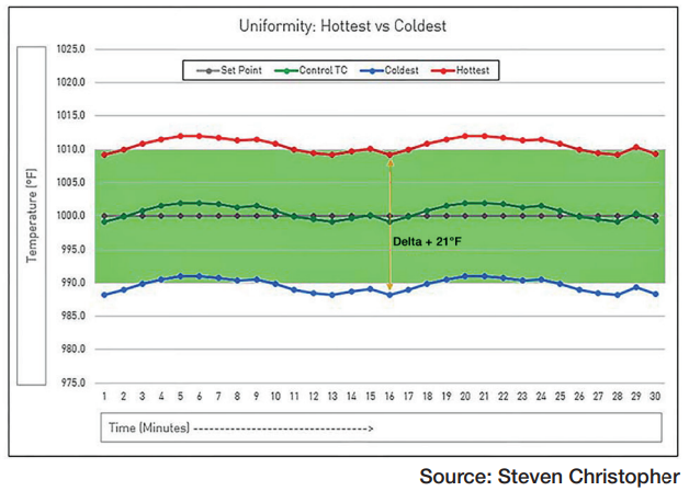
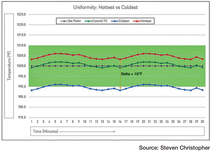
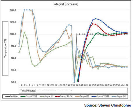
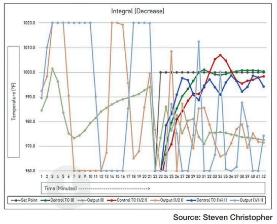
Uniformity is defined by two characteristics: Delta and balance. Delta is the difference between the coldest and hottest temperature. Balance is the relationship between these temperatures and the control TC. Consider Figures 1 and 2 representing an AMS2750F Class 2 furnace with +/-10°F tolerances.
Figure 1 centers around setpoint. With a delta of 21°F, however, no amount of tuning will pass TUS.
Figure 2 reduces delta to 15°F, but the unbalanced nature results in a failing TUS on the lower limit. PIDs will never improve uniformity.
Poor uniformity (Delta) can be overcome by the aforementioned factors and (balance) by adjusting the control TC position or applying an offset (if allowed). The possible combinations are so wide they are beyond the scope of this article.
Pay Attention to Output
Output is an important (and often overlooked) tuning parameter. PID changes are driven by the control TC, but they have practical limits. These limits are often visible in the output well before they are in the control TC. Tuning efforts should always monitor the output for:
Backing off — temperature when output begins to reduce
Stability — ability of output to converge on an appropriate value
Response — noticeable difference in time for the control TC to respond to an output change
TIP: In addition to setpoint and control TC (PV), record output (CV) to better understand tuning. A lot happens in one minute, so try recording every 1–5 seconds if possible.
Healthy PIDs
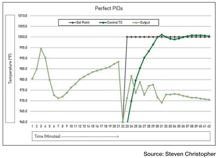
Thermo-Fusion’s vacuum furnace ramped to 1000°F at 40°F/min with an aggressive approach, minimal overshoot and continued a “straight line” at soak (using PIDs of 2.0/75/150). As the control TC neared soak, the output backed off 60°F before the soak temperature — neither too early nor too late. The output settled down after a few quick oscillations, suggesting the Pb was not too small.
Figure 3 demonstrates what PIDs should look like. Now let’s disrupt these values, learning from the result. We begin by exploring Pb’s effect because it has the most influence on the trio.
Figure 3. Perfect PIDs
TIP: When adjusting parameters, go big! Start with large (40–60%) changes, then fine-tune with smaller (10–20%) adjustments.
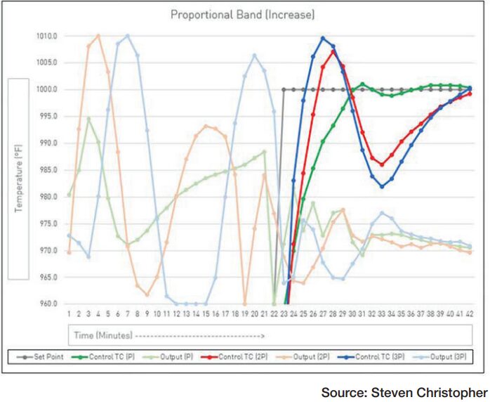
Increase Pb
Figure 4. Increasing Pb
Proportional band influences when output first reduces and how fast it adjusts. The first mostly impacts furnaces experiencing immediate setpoint changes. All furnaces, including those that ramp to final soak, must consider the second — how fast the output adjusts.
A “sweet spot” exists for Pb. Let’s consider the extremes. A Pb of “∞” backs off very early but too slowly. This results in either overshoot followed by slow, rolling oscillations or no overshoot but also failure to reach setpoint. Same cause, but very different outcomes.
Figure 4 demonstrates the first example: reducing early but too slowly to eliminate overshoot.
TIP: Decrease Pb until the output “bounces around”, then slightly increase Pb. This approach offers diminishing returns, with the output eventually becoming unstable.
Decrease Pb
Figure 5. Decreasing Pb
If increasing Pb slows the output, decreasing must offer the opposite effect. A Pb of “0.0” represents on/off control, backing off very late (at setpoint) but quickly (100% to 0% immediately) followed by rapid oscillations. A smaller Pb presents a double-edged sword, which is an advantage to furnaces with an immediate control/output response, but a disadvantage for those with a lagging relationship. This allows the output to wind up or down too much before the control TC responds.
A small Pb minimizes overshoot but sacrifices steady-state control. Pay special attention to the output (specifically the 1/4 Pb line on Figure 5). As the control TC approaches soak, there are tremendous output swings followed by instability — classic signs of too small a Pb.
TIP: Watch the output. If “bouncing around,” increase the Pb, which dampens output.
Increase Integral
Figure 6. Increasing Integral
Integral considers past error, “winding up” as large error exists and adding to the output. Small error conversely “unwinds” the Integral. A larger Integral parameter adds more to the Pb’s output. This may improve aggressiveness, but it sacrifices other aspects of a healthy PID.
Too large an Integral overemphasizes previous error, potentially resulting in overshoot, then quickly unwinding as the error becomes smaller, flattening the control TC. Integral has a second benefit: reducing “droop” as the control TC approaches soak only to prematurely stall. A third benefit compensates for a furnace that heats faster than it cools (or vice versa).
TIP: With similar overshoot to a large Pb, a large Integral differs with less undershoot before stabilizing.
If the control TC stalls before soak without closing, increase the Integral. If the control TC looks more like a saw tooth than a sine curve, increase the Integral.
Decrease Integral
Too small an Integral eliminates the PIDs knowledge of history, leaving all the work to the Pb. Error can change rapidly at any moment, which results in an equally rapid change in output. An appropriately sized Integral offers a smoothing effect on the system. Too small an Integral disregards previous error, possibly making the system unstable.
Figure 7. Decreasing Integral
Changes to Derivative
Derivative is difficult to simplify, but (channeling our inner Malcolm Gladwell) let’s try. Derivative is perhaps most easily thought of as a counterweight to the actions of P-I alone. Derivative evaluates the error’s current rate of change to estimate future error. This forecasting allows Derivative to prematurely reduce or increase output.
Derivative is frequently overused and often not required. Exceptions must be evaluated on a case-by-case basis. A visible indicator suggesting a benefit from Derivative is a delayed response between the control TC and output. As output increases, does the control TC immediately rise? Or does it take a while to respond?
TIP: P-I alone often can’t overcome a significant lag between the control TC and output. Increasing Derivative will counteract the delay.
Summary
We hope this article provides the confidence to take that difficult first step. The beauty of PIDs is they are free to make and easy to undo. Therefore, do not be intimidated in taking that first step. Worst-case scenario, you revert. Pair these tips with the following guidelines, and you will be fine.
Change only one parameter at a time.
Cool the furnace between tests; don’t increase +100°F only to try again.
If you overshoot, don’t abandon ship — observe steady-state. You often learn more from failure than success.
Document, document, document! Simplify your thinking, and don’t simplify your notes.
If stumped, place the controller in manual output, forget the setpoint but watch for stability. If the furnace can’t control, then how can the PIDs?
About The Authors:
Steven Christopher Senior Engineer Super Systems Inc.
Steven Christopher has been involved in countless projects for both captive and commercial heat treaters implementing critical technology applications. He brings a vast knowledge base as it relates to industrial automation, and his experience with heat treat equipment is second to none.