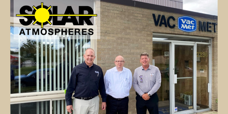
Vac-Met, Inc., a heat treater in the Midwest for 41 years, has been acquired by a North American commercial heat treater.
The addition of Vac-Met within the Solar Family of Companies will increase the total commercial vacuum heat treating and brazing facilities to a total of five (5) plants across the U.S. Their goals of providing commercial heat treating, primarily in a vacuum environment, aligns with Solar’s mission.
Joseph White will continue to head the day-to-day operations of Vac-Met’s nine (9) vacuum furnaces, while leading a team that he has built over the years. Joseph will report to Robert Hill, president of Solar Atmospheres of Western PA. Robert Hill states, "We look forward to continuing to provide unparalleled vacuum thermal processing services to Vac-Met’s valued customers while expanding Solar’s footprint. Solar is excited to support a dedicated and loyal employee base and welcome them to the Solar Team. Together, we will grow the business with unwavering commitment to honesty as our core value."
(Pictured left to right in the image above: Bob Hill, President, Solar Atmospheres of Western PA and Vac-Met; William Jones, Owner/CEO, Solar Family of Companies; Joe White, Vice President of Operations, Vac-Met)
Find heat treating products and services when you search on Heat Treat Buyers Guide.com
What does it mean to "heat treat green"? Between the hype and the cynicism of abilities of "green solutions" to meet climate concerns, there is a robust conversation going on about the real world effects of heat treat technologies and heat treat innovations. In this Technical Tuesday, we'll examine three topics that have been paramount in the discussion over the course of the past year and a half.
If you'd like to read more robust original content from Heat Treat Today, subscribe to the Heat Treat Daily here. Or, if you have a technical article you'd like to share with the North American heat treat industry, contact our editors at editor@heattreattoday.com.
Heat Treating Equipment: Furnaces and Induction Heating
Recently, Solar Atmospheres demonstrated how their new vacuum oil quench furnace is both efficient and safe as well as a "green" alternative to other VOQ methods. Additionally, talk of the greenness of the induction heating process continues to be highly vocalized due to the repeatable and electric method of heating components. Compare these two heat treating equipment technologies below:
Vacuum Oil Quench
"Solar Atmospheres of Western PA announced their newly designed vacuum oil quench furnace (VOQ) has passed startup protocol. There were zero flare and smoke-ups during the quench cycle and the transfer mechanism moved 2000 pound loads with no issues."
Using renewables in the combustion arena of heat treating is a complex topic: real energy used, efficiency, costs, and time to adjust all factor into the discussion. While there still doesn't seem to be one solution to this problem, individuals and companies are drawing lines in the sand to help them make equipment investment decisions for their heat treat operations now.
Overview of the "Renewables" Question
"Using a broad spectrum of green energy sources, likely generated in a decentralized manner, and with regional focus on infrastructure capabilities such as transportation and storage of energy carriers, seems more plausible than focusing purely on an electricity-based energy system."
"But there is really no easy path to replacing the efficiency, both thermodynamic efficiency and economic efficiency, of high temperature heat (flames) — that’s the nature of processing materials. So then, you’re only option is the current affection for “green hydrogen.” This is a profoundly misplaced aspiration."
Water vapor instead of CO2. A huge part of steelmaking is retrieving the pure iron itself in a blast furnace. But this traditional method of getting iron into its usable form requires a lot of heat and a lot of energy. Alternative options that companies are wrestling with are using electric arc furnace (EAF) mills and replacing CO2 with hydrogen. This is a "fringe" conversation to heat treaters, but it is still relevant as downstream manufacturers engineers.
CO2: BOF and EAF Furnaces
"There are a few shifts that need to happen. We must move away from blast furnace steel making. Every product based on that will create huge amounts of CO2. Electric arc furnace (EAF) mills are running the world."
"Around 71 per cent of steel produced today comes from an iron-ore-based method. This typically uses a blast furnace at temperatures of around 1,500°C in which carbon, usually coal, is used to remove oxygen and impurities from the ore to make pig iron. The latter is then turned into steel via a basic oxygen furnace whereby oxygen is blown onto the liquid iron to burn unwanted elements."
"At Cliffs, we don’t want to rely on breakthrough technologies, but rather deal with practical decarbonization options. Our efforts involve the use of the hydrogen contained in natural gas, which is actually a mix of 95% CH4 and 4% C2H6."
Robert (Bob) Hill, FASM President Solar Atmospheres of Western PA Source: Solar Atmospheres
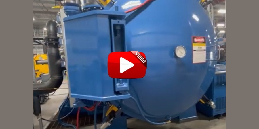
Solar Atmospheres of Western PA announced their newly designed vacuum oil quench furnace (VOQ) has passed startup protocol. There were zero flare and smoke-ups during the quench cycle and the transfer mechanism moved 2000 pound loads with no issues.
"[Recently]," Bob Hill, president of Solar Atmospheres of Western PA, says, "insurance companies are reluctant to write policies for commercial heat treaters simply because they see a single flame or evidence of smoke. In the past, unfortunate accidents have occurred with explosive endothermic atmospheres and flammable oils. I am convinced that this new Solar Manufacturing furnace is a much safer and greener way to oil quench parts."
Watch internal and external camera footage during a quench operation.
The design of the furnace allows for reading work temperatures within the 36" x 36" x 48" hot zone. No oxygen probes are necessary, since the furnace operates with an atmosphere devoid of oxygen. Alloys of dissimilar carbon contents and similar cross sections and austenitizing temperatures can be treated in the same load.
To read about the installation of this VOQ, or to watch a video of the largest component of that installation, click here.
There is an age-old adage that exists in the heat treating world. That supposition states that “the smaller the vacuum furnace, the faster it will quench.” Is this adage true? Explore Solar Atmospheres’ journey as they designed an experiment to discover if pressure or velocity most affects cooling performance.
This Technical Tuesday was written by Robert Hill, FASM, president, and Gregory Scheuring, plant metallurgist, both from Solar Atmospheres. The article originally appeared inHeat TreatToday’sMarch 2022 Aerospace Heat Treating print edition.
Introduction
Our study compared the cooling rates of two distinctly sized High Pressure Gas Quenching (HPGQ) vacuum furnaces — a large 10-bar vacuum furnace equipped with a 600 HP blower motor versus a smaller 10-bar vacuum furnace equipped with a 300 HP motor. Both furnaces, one with a 110 cubic feet hot zone, the other with a 40 cubic feet hot zone, were exclusively engineered and manufactured by Solar Manufacturing located in Sellersville, PA.
History
High Pressure Gas Quenching in the heat treatment of metals has made tremendous strides over recent years. Varying gas pressures within the chamber have been shown to be more governable than their oil and water quenching counterparts. The number one benefit of gas cooling versus liquid cooling remains the dimensional stability of the component being heat treated. In addition, using gas as a quench media dramatically mitigates the risk of crack initiation in a component. This is primarily due to the temperature differentials during cooling. Gas quenching cools strictly by convection. However, the three distinct phases of liquid quenching (vapor, vapor transport, and convection) impart undue stress into the part causing more distortion (Figure 1).
Figure 1. Three phases of liquid quenchants Source: Solar Atmospheres
There are multiple variables involved with optimizing gas cooling. These include the furnace design, blower designs, heat exchanger efficiency, gas pressure, gas velocities, cooling water temperatures, the gas species used, and the surface area of the workpieces. Whenever these variables remain constant, the relative gas cooling performance of a vacuum furnace typically increases as the volume of the furnace size decreases.
The Furnace
Solar Manufacturing has built multiple high pressure gas quenching furnaces of varying sizes over the years ranging from 2 to 20-bar pressure. We have learned that vacuum furnaces, rated at 20-bar and above, became restrictive in both cost constraints and diminishing cooling improvements. Therefore, Solar Manufacturing engineers began to study gas velocities to improve cooling rates. They determined increasing the blower fan from 300 HP to 600 HP, along with other gas flow improvements, would substantially increase metallurgical cooling rates. The technology was reviewed and determined to be sound. A 48” wide x 48” high x 96” deep HPGQ 10-bar furnace, equipped with this newest technology, was purchased by Solar Atmospheres of Western PA located in Hermitage, PA.
Image 1. HFL50 furnace (36” x 36” x 48”)
Source: Solar Atmospheres
Image 2. HFL74 furnace (48” x 48” x 96”) Source: Solar Atmospheres
The Test
Image 3. Test load with thermocouple placement Source: Solar Atmospheres
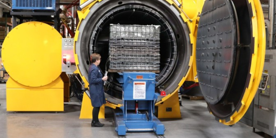
Once this new vacuum furnace was installed, a cooling test was immediately conducted. A heavy load would be quenched at 10-bar nitrogen in an existing HFL 50 sized furnace (36” x 36” x 48”). The same cycle was repeated in the newly designed vacuum furnace almost three times its size! (Images 1 and 2).
The load chosen for the experiment was 75 steel bars 3” OD x 17” OAL weighing 34 lbs each. The basket and grid system supporting the load weighed 510 lbs. The total weight of the entire load was 3060 lbs. Both test runs were identically thermocoupled at the four corners and in the center of the load. All five thermocouples were deeply inserted (6" deep) into ¼" holes at the end of the bars (Image 3). Each load also contained two 1" OD x 6" OAL metallographic test specimens of H13 hot working tool steel. These specimens were placed near the center thermocouple to ensure the “worst case” in terms of quench rate severity. All tests were heated to 1850°F for one hour and 10-bar nitrogen quenched.
Results
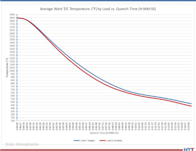
The comparative cooling curves between both HPGQ vacuum furnaces are shown in Chart 1. Table 1 reveals that in the critical span of 1850°F to 1250°F for H13 tool steel, the cooling rate in the larger furnace with more horsepower nearly matched the cooling rate of the furnace three times smaller in size.
Table 1. Critical cooling rates for H13 (1850°F –1250°F) Source: Solar Atmospheres
Chart 1. Average quench rate for five thermocouples Source: Solar Atmospheres
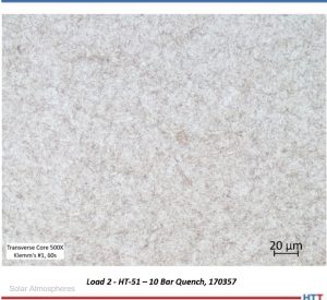
Micrographs of the H13 test specimens processed in each load were prepared (Images 4 and 5). The microstructure of each test specimen is characterized by a predominantly tempered martensitic microstructure with fine, undissolved carbides. The consistency of the microstructure across both trial loads further demonstrates that while the larger furnace utilized the higher horsepower, both resulted in a critical cooling rate sufficient to develop a fully martensitic microstructure.
These tests prove that the greatest impact on the cooling performance in a vacuum furnace is to increase the gas velocity within that chamber. This was achieved primarily by increasing the horsepower of the blower fan. By doing this, the ultimate cost to the customer is significantly less than manufacturing a higher pressure coded vessel. This newly designed vacuum furnace has proven to be a game changer.
Part II of this article will discuss real life case studies and how both Solar and Solar’s customers have mutually benefited from this newest technology.
About the Author:
Robert (Bob) Hill, FASM President Solar Atmospheres of Western PA Source: Solar Atmospheres
Robert Hill, FASM, president of Solar Atmospheres of Western PA, began his career with Solar Atmospheres in 1995 at the headquarters plant located in Souderton, Pennsylvania. In 2000, Mr. Hill was assigned the responsibility of starting Solar Atmospheres’ second plant, Solar Atmospheres of Western PA, in Hermitage, Pennsylvania, where he has specialized in the development of large vacuum furnace technology and titanium processing capabilities. Additionally, he was awarded the prestigious Titanium Achievement Award in 2009 by the International Titanium Association.
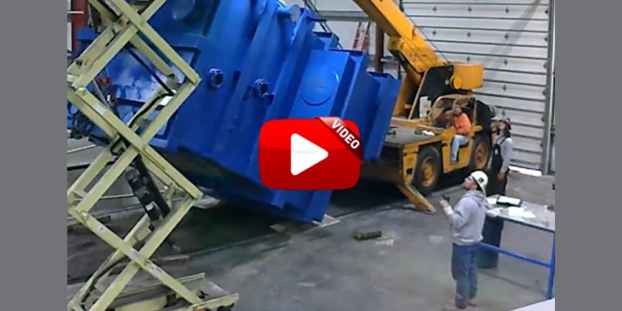
Solar Atmospheres of Western PA received delivery of their vacuum oil quench (VOQ) furnace last week.
This 36” x 36″ x 48” furnace from Solar Manufacturing will be fully installed, tested and operational in early April. See the largest component, a 40,000 pound vestibule/oil quench tank, being transferred and inverted into its pit. This will be the first vacuum oil quench furnace to employ work thermocouples in the actual load!
Solar Atmospheres indicates that they will be releasing updates on this furnace in the future.
Solar Atmospheres Souderton, PA incorporated a high-production vacuum furnace with a work zone of 48″x48″x72″ and a weight capacity of up to 7,500 lbs/batch. The furnace doubles the facility’s hydriding and de-hydriding capacity in the reclamation of titanium and tantalum materials.
Over the past year, we’ve seen numerous new technologies in the way of research, new partnerships, and conversations throughout the industry. So in honor of today being #NationalTechnologyDay, we’re sharing an original content article about just several of these new technologies that are changing the work of heat treaters across North America.
Research
Using HIP to Advance Oregon Manufacturing Innovation Center Programming– “‘Today’s globally competitive manufacturing industry demands rapid innovations in advanced manufacturing technologies to produce complex, high-performance products at low cost,’ observes Dr. Mostafa Saber, associate professor of Manufacturing & Mechanical Engineering Technology at Oregon Tech.”
College Students Implement a NEW Heat Treat Solution with Induction? – “‘We were in shock,’ Dennis admitted, ‘because we didn’t expect it to [work].’ The expectation, Dennis continued, was that something would go wrong, like the lid would not be able to clamp down, or the container would leak.”
The Age of Robotics with Penna Flame Industries – “The computerized robotic surface hardening systems have revolutionized the surface hardening industry. These advanced robots, coupled with programmable index tables, provide an automation system that helps decrease production time while maintaining the highest quality in precision surface hardening.”
Heat Treat Radio: Five experts (plus Doug Glenn) discuss hydrogen combustion in this episode. An easily digestible excerpt of the transcript circulated by Furnaces Internationalhere and is available to watch/listen/read in full for free here.
Heat Treat Radio: Get on-the-ground projections of what technologies Piotr Zawistowski believes will be bringing in the future. Watch/listen/read in full here
Heat Treat Radio: HIP. The Revolution of Manufacturing, that is, according to Cliff Orcutt. Watch/listen/read in full here
Heat Treat Radio: Will indentation plastometry find its way into North America? If you’ve been listening to James Dean, it seems like it already has. Watch/listen/read in full here
Heat Treat Radio: Fluxless inert atmosphere induction brazing. That’s a mouthful! But what is it? Watch/listen/read in full here
A retrofitted vacuum furnace will now produce more metal injected molded (MIM) components with considerably less downtime.
In 2021, a North American heat treater, Solar Atmospheres of Western PA, retrofitted a vacuum furnace for use in a new metal injection molding (MIM) and additive manufacturing (AM) binder removal technology application. The goal was to build a vacuum sintering furnace with a new innovative hot zone and pumping technology that would minimize and target the deposit of detrimental binders evaporating out of MIM and AM parts.
Robert (Bob) Hill, FASM President Solar Atmospheres of Western PA
The hot zone, after a month of repeated 2400°F sintering cycles, remains clean. The problematic binders coalesced at the targeted area within a separate heated pumping port while keeping the primary pump and booster uncontaminated. Most importantly, the client reported that their sintered parts processed in this new furnace never looked better. The MIM parts were extremely bright and met their critical density and dimensional requirements.
The heat treater anticipates considerable maintenance savings on this dedicated furnace versus processing sintering and AM work with binders in a traditional vacuum furnace. Working in a traditional furnace meant added labor and material costs coupled with the lost production time and degradation on the life of the hot zone, which cost the company more than $180,000 per year. The projected maintenance costs on this newly designed sintering furnace will be $10,000 per year.
"Knowing the effects," reported Bob Hill, president of Solar Atmospheres of Western PA, "of what MIM and certain AM processing had done to our equipment in the past, Bill Jones and the engineers at Solar Manufacturing developed an innovative solution for us. Having this newly designed vacuum furnace will be an asset for our future in MIM and AM processing."
Carbon/carbon composite. What is it? Why is the vacuum furnace industry excited about its use in graphite vacuum furnace fixtures, grids, and leveling components?
In this Technical Tuesday, originally published in Heat Treat Today’s November 2021 Vacuum Furnaceprint edition, explore this new material game changer and learn about its versatility in this informative article by Real J. Fradette, senior technical consultant, Solar Atmospheres, Inc., and Roger A. Jones, FASM, CEO emeritus, Solar Atmospheres, Inc.
Roger Jones, FASM, CEO Emeritus, Solar Atmospheres, Inc. Additionally, Real J. Fradette, Senior Technical Consultant at Solar Atmospheres, Inc.
Introduction
The vacuum furnace industry has searched for many years for the ideal material to be used in fixtures and grids for processing workloads at elevated temperatures. The support structures should be lightweight to achieve desired metallurgical results during the cooling phase of the process cycle. These lighter-weight supporting members will also result in overall lower processing costs due to shorter heating and cooling portions of the overall furnace cycle.
The latest and most successful material used in graphite vacuum furnace fixtures, grids, and leveling components is a carbon/carbon composite (C/C) structure. Graphite is an allotrope and a stable form of carbon.
Carbon/Carbon Composite Material
Carbon fiber reinforced carbon matrix composites (C/C composites) have become one of the most advanced and promising engineering materials in use today. These C/C composites consist of two primary components: carbon fibers and a carbon matrix (or binder). They are among the strongest and lightest high temperature engineered materials in the world compared to other materials such as basic graphite, ceramics, metal, or plastic. C/C composites are lightweight, strong, and can withstand temperatures of over 3632°F (2000°C) without any loss in performance.
Ingots processed with graphite support members
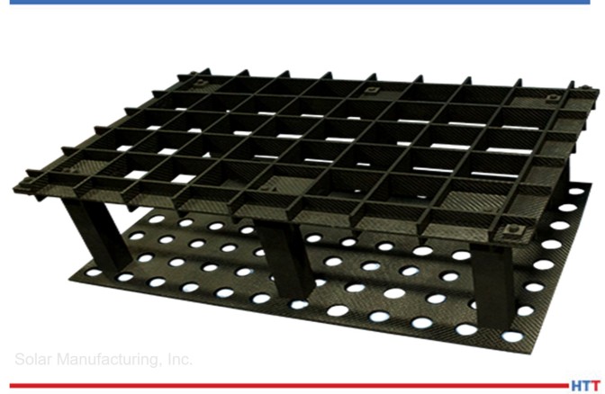
Typical Carbon/Carbon Composite Two-Tier Fixture
Properties of Carbon/Carbon Composites
C/C composites are a two-phase composite material where both the matrix and reinforced fiber are carbon. C/C composites can be tailored to provide a wide variety of products by controlling the choice of fiber type, fiber presentation, and the matrix carbon/carbon composite. They are primarily used for extreme high temperature and friction applications.
C/C composites combine the desirable properties of the two-constituent carbon materials. The carbon matrix (heat resistance, chemical resistance, low-thermal expansion coefficient, high-thermal conductivity, low-electric resistance, low-specific gravity) and the carbon fiber (high-strength, high elastic modulus) are molded together to form a better combined material. The reinforcing fiber is typically either a continuous (long-fiber) or discontinuous (short-fiber) carbon fiber type.
CFC design fixturing for medical implants
Summarizing Properties of Carbon/Carbon Composites
Excellent thermal shock resistance
Low coefficient of thermal expansion
Excellent thermal shock resistance
High modulus of elasticity
High thermal conductivity
Low density (about 114 lb/ft³)
High strength
Low coefficient of friction (in the fiber direction)
Excellent heat resistance in nonoxidizing atmosphere. C/C composites retain their mechanical properties up to 4982°F (2750°C)
High abrasion resistance
High electrical conductivity
Non-brittle failure
Benefits of C/C composites
The carbon fiber matrix can be used to create racks, plates, grids, and fixtures for vacuum heat treating applications.
Various Configurations of C/C Used as Fixtures and Grids
Below are several examples showing different applications of how C/C component graphite materials are used in typical vacuum furnace applications:
347 screens: 347 screens that were annealed at 1875°F in partial pressure nitrogen. The screens were too wide for our normal furnace grid, so we used graphite fixturing to get the screens into the center of the furnace to accommodate the width. The graphite also allows for the screens to settle flat during the heat treating.
Titanium aerospace components: Very intricate and precise graphite fixturing designed to minimize warpage during the solution age heat treatment of these 5-5-5-3 titanium aerospace components. The fixturing was manufactured by 5-axis machining equipment and it allows the part to move during the heat treatment and then settle back into the exact contour of the fixture.
Steel aerospace components: 4340M aerospace components hardened and tempered in partial pressure nitrogen. Graphite fixturing was used to minimize distortion and holes were machined into the graphite plates to help with the cooling phase of the cycle.
Titanium ingots: 10-2-3 titanium ingots homogenized at 2350°F for 24 hours in high vacuum, 10-5 Torr. Each ingot weighs about 10,000 pounds. The fixturing serves two purposes: it keep the ingots from rolling during the heat treatment process, and it also contours to the shape of the ingot so there are no flat spots after the homogenization.
Titanium strips: Titanium strips annealed at 1450°F and aged in high vacuum, 10-5 Torr. Strips were placed on a laser leveled graphite plate to maintain flatness during the run.
Ingot fixtures: These are graphite support members that are used to process the ingots on the first page of the article. They maintain the shape of the ingots while providing support.
The above images are just a small sample of the many supporting graphite designs that have become so critical in vacuum furnace processing. C/C component graphite material can be readily machined for special shapes and applications. We look forward to finding many more ways to successfully use these graphite components.
Heat treating any aerospace projects? Then you know titanium is up there when it comes to VIP alloys in the industry. This best of the web is pulled from an aerospace magazine in which Michael Johnson of Solar Atmospheres answers five questions about creep flattening titanium:
Typical temperatures for creep flattening titanium parts
Whether of not creep flattening can only be done in a vacuum
Best fixturing for creep flattening titanium parts
Can creep flattening minimize movement
Will reheating titanium over 1,000°F affect certification
An excerpt:
"Give your heat treater your material certifications. Many mills will certify to aerospace material specification AMS 2801, AMS 4905, AMS 4911, AMS-H-81200, etc. The material often can be re-annealed while simultaneously creep flattening." - Michael Johnson, Director of Sales, Solar Atmospheres


 Find heat treating products and services when you search on Heat Treat Buyers Guide.com