![]() Carbon/carbon composite. What is it? Why is the vacuum furnace industry excited about its use in graphite vacuum furnace fixtures, grids, and leveling components?
Carbon/carbon composite. What is it? Why is the vacuum furnace industry excited about its use in graphite vacuum furnace fixtures, grids, and leveling components?
In this Technical Tuesday, originally published in Heat Treat Today’s November 2021 Vacuum Furnace print edition, explore this new material game changer and learn about its versatility in this informative article by Real J. Fradette, senior technical consultant, Solar Atmospheres, Inc., and Roger A. Jones, FASM, CEO emeritus, Solar Atmospheres, Inc.

Additionally, Real J. Fradette, Senior Technical Consultant at Solar Atmospheres, Inc.
Introduction
The vacuum furnace industry has searched for many years for the ideal material to be used in fixtures and grids for processing workloads at elevated temperatures. The support structures should be lightweight to achieve desired metallurgical results during the cooling phase of the process cycle. These lighter-weight supporting members will also result in overall lower processing costs due to shorter heating and cooling portions of the overall furnace cycle.
The latest and most successful material used in graphite vacuum furnace fixtures, grids, and leveling components is a carbon/carbon composite (C/C) structure. Graphite is an allotrope and a stable form of carbon.
Carbon/Carbon Composite Material
Carbon fiber reinforced carbon matrix composites (C/C composites) have become one of the most advanced and promising engineering materials in use today. These C/C composites consist of two primary components: carbon fibers and a carbon matrix (or binder). They are among the strongest and lightest high temperature engineered materials in the world compared to other materials such as basic graphite, ceramics, metal, or plastic. C/C composites are lightweight, strong, and can withstand temperatures of over 3632°F (2000°C) without any loss in performance.
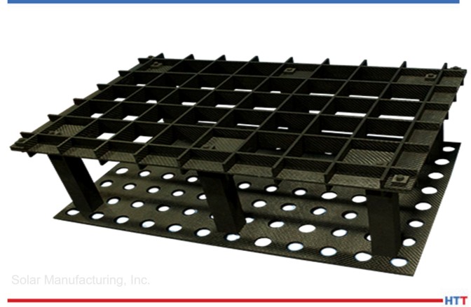
Typical Carbon/Carbon Composite Two-Tier Fixture
Properties of Carbon/Carbon Composites
C/C composites are a two-phase composite material where both the matrix and reinforced fiber are carbon. C/C composites can be tailored to provide a wide variety of products by controlling the choice of fiber type, fiber presentation, and the matrix carbon/carbon composite. They are primarily used for extreme high temperature and friction applications.
C/C composites combine the desirable properties of the two-constituent carbon materials. The carbon matrix (heat resistance, chemical resistance, low-thermal expansion coefficient, high-thermal conductivity, low-electric resistance, low-specific gravity) and the carbon fiber (high-strength, high elastic modulus) are molded together to form a better combined material. The reinforcing fiber is typically either a continuous (long-fiber) or discontinuous (short-fiber) carbon fiber type.

Summarizing Properties of Carbon/Carbon Composites
- Excellent thermal shock resistance
- Low coefficient of thermal expansion
- Excellent thermal shock resistance
- High modulus of elasticity
- High thermal conductivity
- Low density (about 114 lb/ft³)
- High strength
- Low coefficient of friction (in the fiber direction)
- Excellent heat resistance in nonoxidizing atmosphere. C/C composites retain their mechanical properties up to 4982°F (2750°C)
- High abrasion resistance
- High electrical conductivity
- Non-brittle failure

The carbon fiber matrix can be used to create racks, plates, grids, and fixtures for vacuum heat treating applications.
Various Configurations of C/C Used as Fixtures and Grids
Below are several examples showing different applications of how C/C component graphite materials are used in typical vacuum furnace applications:
347 screens: 347 screens that were annealed at 1875°F in partial pressure nitrogen. The screens were too wide for our normal furnace grid, so we used graphite fixturing to get the screens into the center of the furnace to accommodate the width. The graphite also allows for the screens to settle flat during the heat treating.
Titanium aerospace components: Very intricate and precise graphite fixturing designed to minimize warpage during the solution age heat treatment of these 5-5-5-3 titanium aerospace components. The fixturing was manufactured by 5-axis machining equipment and it allows the part to move during the heat treatment and then settle back into the exact contour of the fixture.
Steel aerospace components: 4340M aerospace components hardened and tempered in partial pressure nitrogen. Graphite fixturing was used to minimize distortion and holes were machined into the graphite plates to help with the cooling phase of the cycle.
Titanium ingots: 10-2-3 titanium ingots homogenized at 2350°F for 24 hours in high vacuum, 10-5 Torr. Each ingot weighs about 10,000 pounds. The fixturing serves two purposes: it keep the ingots from rolling during the heat treatment process, and it also contours to the shape of the ingot so there are no flat spots after the homogenization.
Titanium strips: Titanium strips annealed at 1450°F and aged in high vacuum, 10-5 Torr. Strips were placed on a laser leveled graphite plate to maintain flatness during the run.
Ingot fixtures: These are graphite support members that are used to process the ingots on the first page of the article. They maintain the shape of the ingots while providing support.
The above images are just a small sample of the many supporting graphite designs that have become so critical in vacuum furnace processing. C/C component graphite material can be readily machined for special shapes and applications. We look forward to finding many more ways to successfully use these graphite components.
About the Authors:
Real J. Fradette is the senior technical consultant at Solar Atmospheres, Inc.
Roger Jones is the FASM and CEO Emeritus at Solar Atmospheres, Inc.