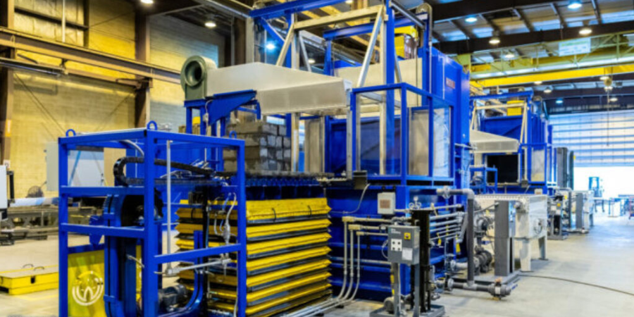
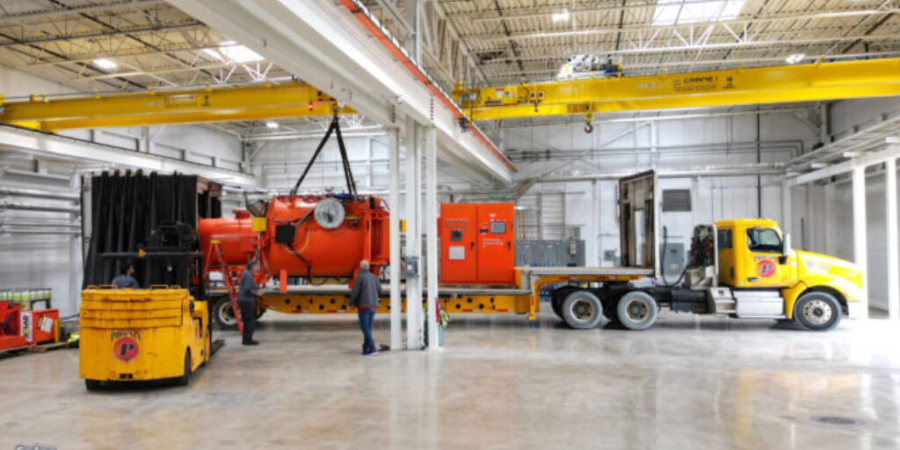
Two electrically heated horizontal quench systems have been shipped to a supplier for the semiconductor industry. The systems will be used for the annealing and rapid cooling of various high purity alloy parts.
The operating procedure for each horizontal quench system from Wisconsin Oven includes loading the product on a work grid located on the loading platform. Once the load is lifted into place, a pusher/extractor mechanism located at the front of the quench tank moves the load onto the quench lift platform, then the furnace pusher/extractor mechanism pulls the load into the furnace for annealing.
After completing the heating cycle, the vertical lift door opens, the furnace pusher/extractor transfers the load onto the quench lift platform, and the load is lowered into the water quench tank. After the load has sufficiently cooled, the quench lift is raised, and the front mounted pusher/extractor mechanism pulls the load back onto the scissor lift. While the load is pulled onto the scissor lift, a blow off system removes the majority of the water from the load.
See below to watch a video of this system in operation.
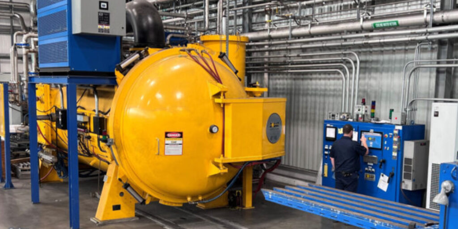
Solar Atmospheres has announced the order of a new 10-bar vacuum furnace for their Greenville, South Carolina, heat treat facility.
This horizontal vacuum furnace (48” wide x 48” high x 96” deep) will be manufactured by sister company Solar Manufacturing. The furnace is capable of processing up to 12,000-pound loads and is scheduled to be installed in late 2024. This new vacuum furnace will feature a vacuum pumping system capable of achieving an ultimate vacuum of 1x10⁻⁶ Torr, which is crucial for processing titanium and other high grade alloys. Additionally, this furnace will apply newly developed designs for the uniform and rapid cooling of large workloads.
Steve Prout, president of Solar Atmospheres Southeast, states, “We are proud to be offering our customers another regional option for high pressure quenching of large components and workloads, as well as the opportunity to leverage economies of scale to reduce their cost of thermal processing in the midst of the challenging economic environment we are all facing.”
Find heat treating products and services when you search on Heat Treat Buyers Guide.com
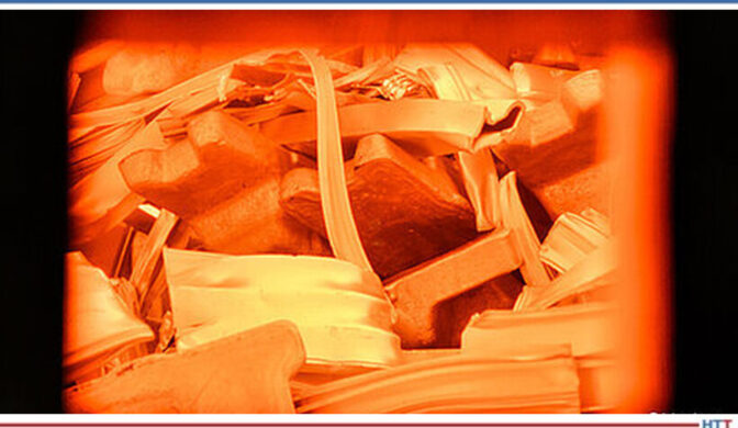
Skana Aluminum Company in Manitowoc, Wisconsin, has recently been supplied with an Exogas™ exothermic atmosphere generator.
The atmosphere generator from SECO/WARWICK USA, an American SECO/WARWICK Group subsidiary, provides an indirect-chilled exothermic atmosphere for annealing, brazing, normalizing, drawing, and tempering.
Says Marcus Lord, managing director of SECO/WARWICK USA, “At 30,000 CFH, it is one of the largest atmosphere generator units we’ve made to date. It should be plenty large enough to meet the exothermic atmosphere needs of the multiple processes within the Skana plant.”
Skana has also placed an order with the furnace supplier for a smaller atmospheric gas drier for use elsewhere in the plant.
Find heat treating products and services when you search on Heat Treat Buyers Guide.com
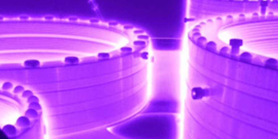
Nitriding and nitrocarburizing may be familiar terms in the industry, but which process — ion/plasma nitriding, gas nitriding, or nitrocarburizing — is best for your heat treat operations?
In this best of the web article from Advanced Heat Treat Corp., discover the specifics of each of these surface treatments and compare their benefits for wear resistance and corrosion resistance. Explore also the innovative technologies developed by the North American heat treater for optimization of these processes. for optimization of these processes. You will encounter technical diagrams, high quality images of nitrided/nitrocarburized parts, and in-depth technical comparisons of these processes.
An excerpt:
Well-controlled nitriding significantly enhances wear resistance and lowers coefficient of friction in many applications of steel components. For certain steels, nitrided samples show even better tribological behavior than carburized samples of the same steels.
What are qualities and best practices of a good leader? Joe Theismann, former quarterback for the Washington Redskins and present-day entrepreneur, invites Heat TreatToday'sreaders and 40 Under 40 honorees to contemplate leadership, specifically the successful leadership that is found by giving back.
This article was originally published in Heat TreatToday's September 2023 People of Heat Treat print edition.
Joe Theismann
Entrepreneur, Former Washington Redskins Quarterback, Football Analyst
Source: Heat TreatToday
Congratulations to the 40 Under 40 Class of 2023. What an honor to be recognized as up-and-coming leaders in the heat treat industry. I am excited for you and the opportunities you have to lead and help those around you succeed. Because success is found by giving back. That may be something you don’t hear often, but I truly believe we must measure success by the way we are helping others.
Contact us with your Reader Feedback!
With leadership comes responsibilities. As a former professional quarterback as well as an owner of several businesses, I’ve learned a few key principles that I hope will be helpful as you grow as leaders. When performed effectively, they will set up you and your team well.
To succeed by giving back to others, start with the 3 E’s — environment, expectations, and execution.
Environment
The environment, or culture, encompasses the people with whom you work and lead. Being intentional about the kind of culture you create is vital to fostering innovation and freedom of communication. Enthusiasm is the engine that drives, and your attitude precedes everything.
Relationship building is key. Mentoring others by sharing your experiences and expertise is as important as learning from your mentees. Listen and learn — seek knowledge every day and don’t think you have all the answers. It’s the whole of the team that matters. Asking yourself what you can do to help others succeed is a vital component to building a healthy culture that will enable others to shine.
Expectations
Lead by explaining your “why” — be sure you know it and articulate it well. The details are critically important; ensure your team understands your expectations.
To know your why, identify your direction and practice disciplined leadership. Bill Parcells, former head coach of the New York Giants, talked about the importance of direction and discipline. Be definitive in providing direction and model discipline to stick with the task. Embrace the failures, learn from them, and encourage others to not fear them; it’s a process. Share these insights with your team!
Execution
Finally, if you’ve built a healthy environment and your team understands your expectations, lead with present-minded execution.
So, think about today, not yesterday; ask, “What is prevalent today?” And, with every day, be sure you are available to those who need you.
Be reliable in showing up to do the hard work. And be accountable to those you are leading and those to whom you report. Have their backs. Be proud of who you are and who you represent. Execute with confidence.
When Roadblocks Open Doors to True Success
What happens when you experience an unexpected roadblock in this wild adventure called life? Because you know it’s going to happen!
In 1985, during a Monday night game against the Giants, I suffered a severe fracture to my right leg between the knee and ankle that eventually led to my retirement from football. Sure wasn’t expecting that.
What I had to do was find another path that provided me with the same passion as the one that just closed. Was it difficult at first, yes, but because I spent time learning my trade, I was able to work as a sportscaster and pro football analyst for many years and loved it!
Mental toughness will be necessary when you hit those curves. It may not throw you out of the game, but it might throw you off. Focus on persevering, finding that passion, and remembering that success is found in giving back.
Congratulations! I look forward to seeing your success in the lives of the people you lead.
About the Author:
Joe Theismann is the former two-time Pro Bowl star quarterback for the Washington Redskins where he played for 12 seasons and led them to winning Super Bowl XVII. Most recently, he spent the last two decades working for ESPN and the NFL Network as an NFL analyst. He is also a successful restauranteur.
Solar Atmospheresof Michigan has begun the relocation of the first of eight existing vacuum furnaces from the old Vac-Met premises.
The first vacuum furnace (38” wide by 28” high by 72” deep), decommissioned from the Fraser Michigan plant, will be fully operational this week in the Chesterfield, Michigan, facility.
The migration of the next seven vacuum furnaces and other ancillary equipment, originating from both the Fraser, MI, and Warren, MI, plants, will occur every two weeks. By the end of 2023, the transferred assets will join the new existing Solar vacuum furnaces to form a new state of the art vacuum thermal treating facility in Michigan.
Robert (Bob) Hill, president of Solar Atmospheres of Michigan, comments, “To have all of our operations under one roof is a massive step for our employees and our company. Ownership of the vacant lot next to us gives the opportunity to grow the business more efficiently in one location. We are excited to get through this transition phase and look forward to 2024 and beyond!”
To view a video of the relocation process, see here.
Heat TreatToday is partnering with two international publications: heat processing, a Vulkan-Verlag GmbH publication that serves mostly the European and Asian heat treat markets, and Furnaces International, a Quartz Business Media publication that primarily serves the English-speaking globe. Through these partnerships, we are sharing the latest news, tech tips, and cutting-edge articles that will serve our audience — manufacturers with in-house heat treat.
In this article, all eyes are on CO2 and hydrogen.
RATH Limiting CO2 Emissions with Furnace Operations
At the RATH plant in Krummnußbaum, Lower Austria, two new vacuum nitriding furnaces are being operated. (Source: heat processing)
“[Two] new vacuum nitriding furnaces, used exclusively for the production of silicon carbide plates and bricks in a nitrogen atmosphere, are now being operated with electricity. The result: CO2 emissions are around 70% lower than with the previous gas-fi red furnace, and fossil fuels are reduced to a minimum.”
Bigger, Greener, and Employee-Centered Growth in France
Pfeiffer Vacuum Technology AG announced in May 2023 a seven-year, €75 million investment plan for its Annecy site. (Source: heat processing)
“Our investment plan will serve to modernize and digitalize our production in order to continue our growth. We want to double the operations of our French subsidiary with a sales target of €600 million by 2030 and create 100 to 150 additional jobs,’ emphasized Dr. Britta Giesen, CEO of Pfeiffer Vacuum. During the same period, the Group intends to accelerate its course to reduce its CO2 emissions in Scope 1 and 2 to net zero by 2030.”
£4.6m Grant Assistance for Novelis To Establish Hydrogen
Burning Trials
With the recently awarded grant by the Department for Energy Security & Net Zero, Novelis’ Latchford plant will test the use of hydrogen on one of its recycling furnaces in a demonstration phase in 2024.
(Source: Furnaces International)
“Depending on the final configuration, replacing natural gas with hydrogen to feed the remelting furnace could reduce CO2 eq emissions by up to 90% compared to using the same amount of natural gas.”
Fives and Hydro Successful Batch of Hydrogen-Fueled Recycled Aluminum
Green hydrogen is one of the most promising emission-free fuels to address the environmental challenges of heavy polluting industries, including aluminium.
(Source: Furnaces International)
"The test in Hydro Extrusion’s plant is the world’s first on an industrial scale. The natural gas was successfully replaced with green hydrogen in the recycling of aluminium, a key step towards decarbonization of Industry.”
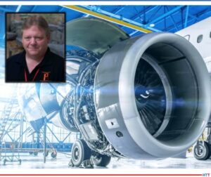
Thinking about travel plans for the upcoming holiday season? You may know what means of transportation you will be using, but perhaps you haven't considered the heat treating processes which have gone into creating that transportation.
Today’s Technical Tuesday original content round-up features several articles from Heat TreatToday on the processes, requirements, and tools to keep planes in the air and vehicles on the road, and to get you from one place to the next.
Standards for Aerospace Heat Treating Furnaces
Without standards for how furnaces should operate in the aerospace, there could be no guarantee for quality aerospace components. And without quality aerospace components, there is no guarantee that the plane you're in will be able to get you off the ground, stay in the air, and then land you safely at your destination.
In this article, written by Douglas Shuler, the owner and lead auditor at Pyro Consulting LLC, explore AMS2750, the specification that covers pyrometric requirements for equipment used for the thermal processing of metallic materials, and more specifically, AMEC (Aerospace Metals Engineering Committee).
This article reviews the furnace classes and instrument accuracy requirements behind the furnaces, as well as information necessary for the aerospace heat treater.
Dissecting an Aircraft: Easy To Take Apart, Harder To Put Back Together
Curious to know how the components of an aircraft are assessed and reproduced? Such knowledge will give you assurance that you can keep flying safely and know that you're in good hands. The process of dissecting an aircraft, known as reverse engineering, can provide insights into the reproduction of an aerospace component, as well as a detailed look into the just what goes into each specific aircraft part.
This article, written by JonathanMcKay, heat treat manager at Thomas Instrument, examines the process, essential steps, and considerations when conducting the reverse engineering process.
If you are one of the growing group of North Americans driving an electric vehicle, you may be wondering how - and how well - the components of your vehicle are produced. Electric vehicles (EVs) are on the rise, and the automotive heat treating world is on the lookout for ways to meet the demand efficiently and cost effectively. One potential solution is laser heat treating.
Explore this innovative technology in this article composed by Aravind Jonnalagadda (AJ), CTO and co-founder of Synergy Additive Manufacturing LLC. This article offers helpful information on the acceleration of EV dies, possible heat treatable materials, and the process of laser heat treating itself. Read more to assess the current state of laser heat treating, as well as the future potential of this innovative technology.
When the Rubber Meets the Road, How Confident Are You?
Reliable and repeatable heat treatment of automotive parts. Without these two principles, it’s hard to guarantee that a minivan’s heat treated engine components will carry the family to grandma’s house this Thanksgiving as usual. Steve Offley rightly asserts that regardless of heat treat method, "the product material [must achieve] the required temperature, time, and processing atmosphere to achieve the desired metallurgical transitions (internal microstructure) to give the product the material properties to perform it’s intended function."
TUS surveys and CQI-9 regulations guide this process, though this is particularly tricky in cases like continuous furnace operations or in carburizing operations. But perhaps, by leveraging automation and thru-process product temperature profiling, data collection and processing can become more seamless, allowing you better control of your auto parts. Explore case studies that apply these two new methods for heat treaters in this article.
Two new furnaces are about to go live for Wallwork Group Ltd. These furnaces will increase the heat treating capacity within the group and help the demand for the aerospace and general engineering industries.
These furnaces from SECO/WARWICK, an international industrial furnace company with North American locations, are capable of 10bar pressure quench and designed to deal with increasingly detailed customer specifications. Joining Wallwork Group's current heat treat capacity, consisting of sealed quench, plasma and gas nitride, vac braze, salt nitrocarburize, PVD coatings, and a hot isostatic pressing center, these new furnaces will further expand heat treating potential for aerospace and general engineering.
Find heat treating products and services when you search on Heat Treat Buyers Guide.com
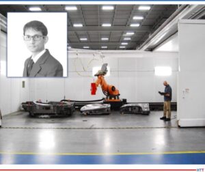
Batch or continuous — which equipment is better for your operations? Today’s Heat Treat Radio episode is a lunch & learn to answer your burning question about batch IQ vs. continuous pusher furnace systems. Michael Mouilleseaux of Erie Steel is a boots-on-the-ground expert in North American heat treat, and he’ll share a bit about the history of these systems before getting into the equipment and heat treat processing differences.
Doug Glenn, Heat TreatToday's publisher and the Heat TreatRadio host, Karen Gantzer, associate publisher/editor-in-chief, and Bethany Leone join this Heat TreatToday lunch & learn.
Below, you can watch the video, listen to the podcast by clicking on the audio play button, or read an edited transcript.
The following transcript has been edited for your reading enjoyment.
The History of Batch and Pusher Furnaces (00:52)
Contact us with your Reader Feedback!
DOUG GLENN: Can you talk with us a little bit about the whole history of batch furnace versus pusher furnace?
MICHAEL MOUILLESEAUX: Sure. And thank you for having me!
Interestingly enough, the pusher furnace — which we might say is a more complex piece of equipment than a batch integral quench furnace — preceded the batch furnace. Atmosphere pushers were around prior to World War II. I spoke with a number of folks in the industry and asked, “How could that possibly be, given the level of complexity?” Interestingly, pushers were available because the atmosphere was generated by a charcoal generator.
If you think back to pack carburizing, we used charcoal and some accelerator. You would put it in a closed container, you’d heat it up, and that’s how you carburized things before you had atmosphere furnaces. Utilizing that same concept, they generated an atmosphere, put it in a furnace, and pushers were the first ones to do that.
So, who were the folks who did that? They were AFC-Holcroft, Surface Combustion, and Ipsen, all the usual characters and suspects there.
Pusher furnaces were available in single row and multiple row configurations.
They were heated with gas or electricity. I have to think that the earlier ones were heated by gas. Typically, they employed oil quenching. Although atmosphere cooling could be in the works, to find something of that vintage is very difficult. Maybe someone listening to this will weigh in and say, “Well, let me help you with that.”
The batch integral quench furnace is post World War II. What precipitated the development of the batch integral quench furnace was the development of the atmosphere generator, and that’s thanks to and around 1941 he actually published a book on atmosphere generators. I’m not sure where to find documentation of the patent he was granted for this generator. It might be interesting to discover. But again, Lindberg, Surface, Ipsen, — all these folks had these furnaces in the late 40s/early 50s.
When they started out, these furnaces were relatively small. The furnace might have had a tray that was 12 inches x 12 inches x 8 inches tall. You’d struggle to fit a hundred pounds into something like that.
But the batch furnace is by far the most popular atmosphere furnace that is available. You’ve got a variety of processing capabilities, which makes very flexible. There are a wide variety of sizes, even today; it can be heated with electricity or gas (we’ll talk about that a little bit later). You can have an oil quench furnace, you can use a polymer quench, and you can have a furnace where you atmosphere-cooled the load after it was processed in the primary furnace.
During this discussion, I’m going to use “batch,” “batch IQ,” and “batch integral quench” semi-interchangeably. So, if I say “batch” and I forget the “IQ” or if I say “batch integral quench” — these are all the same pieces of equipment. We have numerous names for the same thing.
DOUG GLENN: Gotcha. You said the continuous furnace came first because the atmosphere was being created by burning charcoal inside the furnace, that created a carbon rich environment?
MICHAEL MOUILLESEAUX: Actually, it was a generator that was pumped into the furnace.
DOUG GLENN: Got it. That was confusing; I was wondering how they were burning charcoal inside a furnace.
MICHAEL MOUILLESEAUX: Actually, it was explained to me that because the pusher furnace was so much larger, when you would open the doors to place or extract a load, the relative pressure drop of opening a door wasn’t that great. So, these primitive charcoal generators could accommodate that.
But in a batch furnace, arguably, the door is one wall of the furnace, and you couldn’t create a sufficient amount of pressure in the furnace. So, it had to wait until we had endothermic generators so that we could establish a furnace pressure higher than atmospheric pressure to make batch furnaces. It’s fascinating.
Basics of the Batch Furnace (05:41)
DOUG GLENN: And as you said, it is probably the most popular furnace used today by many, many heat treaters. Let’s talk about batch furnaces, here we go.
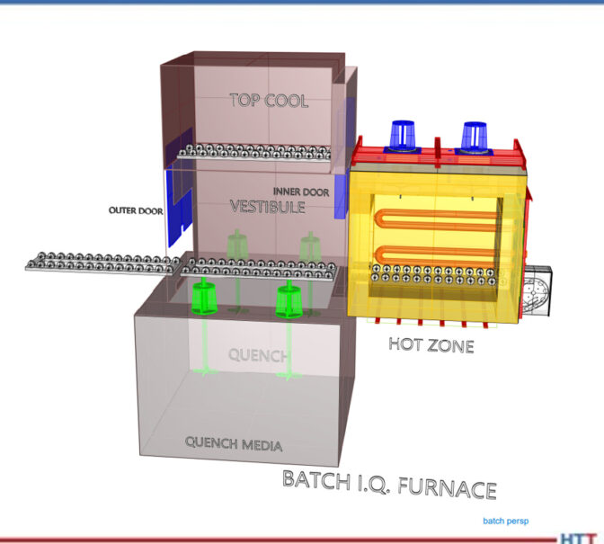
MICHAEL MOUILLESEAUX: Let’s look at the CAD drawing for a batch furnace. The batch furnace is primarily two components. You can see the hot zone — that is the furnace proper. It’s highly insulated, it has radiant tubes in it (so we can put atmosphere in the furnace), and the heating portion does not affect the atmosphere.
It is loaded through a vestibule, and the vestibule is pressurized as well. A load can go into a vestibule, you can close the door, you open the inner door, the load goes into the furnace, you can process it and then, as you can see, you can either quench the load or you can top cool the load.
CAD drawing of a batch furnace.
Common Processes in a Batch Furnace (06:31)
What kind of things can we do in an atmosphere furnace? Answer: operations that do not require quenching. We could stress relieve, we could subcritically anneal, we could supercritically anneal (so, above and below 1350/1400 Fahrenheit), and then we can normalize.
Normalizing is utilized for products like forgings or castings which are made at a very high temperature. You’ve got a number of structures in the component and what you want is a “normal” structure. You want a uniform structure throughout the part so that it can be machined.
Normalizing is typically performed at a high temperature, and it’s put into this top cooled/atmosphere cooled chamber. In the old days, that was termed “air cooling” — it was a rate equivalent if you just set it out in air. These top cooled chambers are somewhat insulated; they have cooling jackets that are in the side, and there is a fan in them so you can circulate the atmosphere through it so that you get uniform cooling throughout the load.
DOUG GLENN: Michael, this isn’t considered high pressure gas quenching though, right?
MICHAEL MOUILLESEAUX: Not even close.
In this animation, we have the load going into the furnace, the vestibule door closes, the furnace door opens, the furnace door closes, we perform whatever process we want, we extract the load out of the furnace, and it goes up into the top cool chamber. It’s then atmosphere cooled. When that is completed, we take the load out.
The time in the furnace could be four hours (plus or minus). The time up in the top cool chamber would probably be an hour or two. Once the load is extracted from the furnace and is put into the top cool chamber, and you reestablish pressure in the vestibule, you actually open the outer door, put another load in and start processing the next load while the initial load is being cooled.
Then, there are processes that require quenching. In degree of simplicity, first there is neutral hardening. Neutral hardening implies that the atmosphere in the furnace is neutral with the carbon content of the steel. So, for a 30-carbon steel, you’d want a 30-carbon atmosphere; for a 40-carbon steel, you’d want a 40-carbon atmosphere. The optimum is to neither enrich nor to deplete the surface carbon; you don’t want to change the chemistry. Typically, neutral-hardened parts are subsequently oil-quenched.
Then, there is carbonitriding. In carbonitriding, you have a high carbon atmosphere. You also introduce ammonia into the furnace. The ammonia dissociates right in the furnace. The carbon and nitrogen diffuse into the surface of the component. is held at a sufficient temperature to attain the case step that is desired, then, again, it is extracted into the vestibule, and it is quenched.
Carburizing would be another process. It’s similar to carbonitriding, except there is no ammonia. It’s only carbon that’s diffused into the surface of the part. Typically, parts that are carburized are oil-quenched.
There are, however, strategies and components where you would carburize, and then you would take the part and you would top cool it. You might take the part out of the furnace, and you may reorient it. So, parts that are distortion-critical may be oriented in one direction for carburizing, and then reoriented for hardening. You may carburize twice as many parts as you harden, so the hardening load would be half the size.
A low temperature process which is more complex is ferritic nitrocarburizing. That, typically, is performed around 1000°F. It is performed in batch furnaces, as well. Typical process cycles for that are going to be, at temperature, an hour and a half/two hours. That process can either be atmosphere cooled or it can be quenched; it depends on whether you’re looking for solid solution hardening or if you’re just looking for the nitrided layer and you’re not trying to do anything to the substrate.
I think that we have an animation for this.
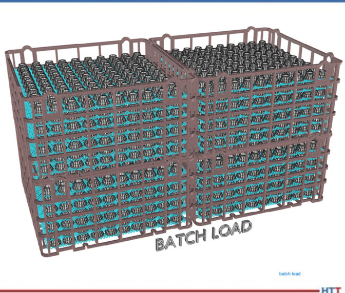
Diagram of a batch system load.
Again, the load is loaded in the vestibule, the vestibule pressure is reestablished, the load is put into the furnace and, at that point, we perform whatever operation it is that we want to do of those previously described operations.
In the animation, you can see that the load is immersed in the quench. Following the quenching operation, it’s withdrawn from the furnace.
The total time for quenching is 10 minutes. When the load is brought up out of the oil, typically you let it sit there and allow it to drip so the precious quench oil you’ve paid your money for can go back into the quench. You’re washing and removing as little quenchant as is possible. In the heat treating operation, quenching is the single most critical portion of the operation.
A Note on Quenching (12:32)
MICHAEL MOUILLESEAUX: When we’re carburizing, we have a portion of an hour where there would be no significant change in the case depth of the part. When we temper the parts, we have hours. You could temper it for three hours, you could temper it for five hours, and you’re not going to have a material change in what’s performed. In the quenching operation, the latitude that you have in quenching is in seconds.
Our typical protocol is that when a load is extracted from the furnace, from the time that the furnace door opens into the vestibule to when the load bottoms out at the bottom of the quench, in a batch furnace, must be 40 seconds maximum.
DOUG GLENN: 40?
MICHAEL MOUILLESEAUX: 40 seconds maximum. Typically, it’s done in 20 or 25 seconds. But it’s 40 seconds maximum. In a pusher, that number is 30 seconds maximum. This is something that you track; it’s data logged. If it exceeds that, at that point, you’re going to have to perform some inspection on that load that is much higher and much more intense had it not taken that much longer.
DOUG GLENN: Can you, very briefly, explain why is it so important? I’m assuming it has something to do with martensite start and martensite finish and all that good stuff, but is there a layman’s way of explaining why the time to quench is so important?
MICHAEL MOUILLESEAUX: Essentially, you want to have the load at a uniform temperature when it goes into the quenchant. If we have a significant variation in the low temperature, from the top to the bottom or the front to the back — even if the quenching operation is completely uniform — we’re going to have a variation in properties, variation in hardness, and certainly the probability of variation in core hardness.
For those things that are distortion-critical, it is absolutely important that the load has a similar temperature, across the load, top to bottom, inside to out, when it’s quenched.
Batch Furnace Systems (15:00)
MICHAEL MOUILLESEAUX: You typically don’t have a singular furnace, you have a system. What’s involved in a system?
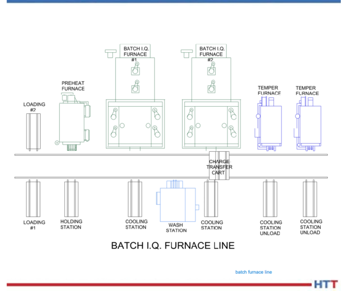
What we’re looking at here is a relatively simple system. You have a loading operation. Obviously, the parts need to be loaded in baskets or fixtures. In some way, the load needs to be built. Typically, there is a station for that.
Diagram of a batch system furnace line.
Following loading, it’s put into a preheat furnace. A preheat furnace is identical to what we would call a “temper” or a “draw.” You can thermally clean the parts by heating them up to 800°F. The other thing is that those that you put into that part are 20% the cost of getting those BTUs when you’re putting it in the high heat furnace, so it just makes economic sense. You’re cleaning the parts and you’re preheating the parts.
Then you’re going to put it into the furnace to perform the furnace operation; it’s either going to be top cooled or quenched. If it’s top cooled, you’re going to stop that top cooling operation at 300°F or 400°F. You’re going to put it in a cooling station and allow it to cool to room temperature. If you quench the part, if you’re modified marquenching it, it’s 250°F plus; if it’s quenched in regular oil, it could be 150–180°F.
The next operation is to wash the part. Typically, you don’t want to wash hot parts; you want to allow them to cool to room temperature. Sometimes you do, but more often than not, no.
Then there’s the wash station; you’re washing the parts. Then, you’re taking them out of the washing station and allowing them to drip. Then, you’re going to put them into a temper and you’re going to temper it for three to seven or eight hours, or something of that nature. You extract the load from the tempering furnace, put it in a cooling station, and allow it to cool down to room temperature so you can then unload it.
As you can see, the way that is accomplished is with this transfer cart. The transfer cart extracts the load from the loading table, pushes it into the preheat furnace, pulls it out of the preheat furnace, and pushes it into the batch furnace. Then the batch furnace quenches it, but when the outer vestibule door is opened, the transfer car must go in and get the load and pull it back onto the transfer car. The car pushes it across the aisle into the cooling station, picks it up, puts it in the wash, takes it out of the wash, puts it into the temper, takes it across the aisle when the tempering is finished, extracts it from the temper, and puts in on the cooling station. That transfer cart is an important piece of equipment.
But you can see there are a lot of moving parts to this. And you might ask, “Why would you do this?” Well again, because of the flexibility of the batch furnace. In this example, batch furnace #1 can be performing neutral hardening; batch furnace #2, at the same time, can be carbonitriding; the neutral hardening load finishes and the next load that goes in there could be annealed; after the load is annealed, then you could take a load and it could be normalized; then you could go back and you could neutral harden again.
So, if you don’t have multiple loads of the same thing, this offers a degree of flexibility that almost is not available in any other type of atmosphere processing equipment.
DOUG GLENN: Right. And the fact that you have more than one furnace, more than one high heat furnace, more than one temper furnace, gives you almost (not exactly, but closer to) a continuous process even though each furnace is a “batch,” if you will.
MICHAEL MOUILLESEAUX: Correct.
There are charge cars that are automated, so the charge car knows where the loading station is — it goes to that loading station. You could either have a human unload it or, in the highest degree of automation, it gets there and you have a PLC that is overseeing or supervising this entire operation, and it would know to take that load onto the cart, where to take it next, and what to do. It becomes a semi-automated method of heat treating.
Properties of the Pusher Furnace (19:53)
DOUG GLENN: Let’s move on to the pusher furnace, the continuous system.
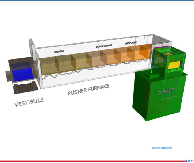
MICHAEL MOUILLESEAUX: The pusher furnace, as you can see in this description, contains the vestibule, the furnace, and the quench. We’ve just broken it down into the pusher furnace proper.
Diagram of a pusher furnace.
Loads are put into the vestibule and then, sequentially, they move their way through the furnace. The first zone of the furnace would be what we would call the “preheat” and that’s where we bring the part up to temperature.
In this example, we’re showing boost-diffuse. This is an example where we would be carburizing. The first couple of positions would be a boost. We carburize at a higher carbon content because it diffuses more rapidly at the initial point of carburizing. Then, at the tail end of the carburizing cycle, we reduce the carbon content to what our desired surface carbon content would be.
An example might be: We would start out and we’d boost at 1% or 1, and the diffuse cycle would be .8% carbon. You do that for a couple of reasons: You want to mitigate any retained austenite, so the bar is quenched at a higher carbon. You have opportunity for development of an unacceptable amount of retained austenite. At the extreme, you could start developing carbides and those become very difficult to re-solution. That’s the rationale for having a boost-diffuse. You do that same thing in a batch furnace; I just didn’t describe that as such.
And then the drop zone. We want to reduce the temperature prior to quenching so that we have very uniform quenching properties and if the components that we’re heat treating are distortion-critical, it’s very important as to what the temperature is prior to quenching.
So, we carburize at a high temperature (1700 Fahrenheit/1750 Fahrenheit), because the diffusion rate is much higher at that temperature. But we only want to quench these parts at 1500 or 1550 Fahrenheit because we want to have an absolute minimum amount of distortion.
Every hour, the vestibule door to the quench is going to open and you would cross-push that load into the quench vestibule, you would close the door, and just as the animation described in the batch furnace, that load would drop on an elevator into the quench.
Now that we’ve done that, we have an opening. That last position is open. So, we go to the vestibule on the front end of the furnace, we open that door, we put a load in there, we close the door, and we’ll close it long enough for us to reestablish the furnace pressure (no more than 3–5 minutes). Once we’ve established furnace pressure, we can open the door between the vestibule and the first preheat zone, and then to the left of the vestibule is going to be a mechanism for pushing these loads, hence the term “pusher”? Could it be hydraulic? It could. Could be mechanical? Both are employed.
What you’re doing is pushing it further by one position. Because the last position is open, the second to the last load progresses into the last position, the load that you put in the vestibule goes into the first position.
DOUG GLENN: A couple quick questions: Really, the sequence starts with the load being pushed out of the furnace into the quench vestibule and then dropped in. That leaves that last spot open in the furnace. Then everything else starts and we push it all down, correct?
MICHAEL MOUILLESEAUX: You are correct.
DOUG GLENN: In this illustration, it looks like there are divisions between each of these different locations. In the preheat, it looks like there are three or four; in the boost-diffuse, it looks like you’ve got two or three. Those aren’t actually physical barriers; You’re just showing where the load would progress to, correct?
MICHAEL MOUILLESEAUX: You are correct.
DOUG GLENN: Are there any chamber divisions in a pusher furnace?
MICHAEL MOUILLESEAUX: In a pusher furnace, you have arches above the load and that helps to compartmentalize. The key word there is “helps.” You don’t have an actual compartmentalization.
Let’s say that we want to perform a carburize at 1700°F in this furnace. If you had three preheats, you may want to perform these somewhere below the 1700°F with the last position being at 1700°F so that the load that goes into the carburizing zone is at temperature and it’s ready to accept carbon.
The carburizing zone would all be at the same temperature, but you have to understand these parts are all at 1700°F and we want to quench it at 1550°F, let’s say. We have two positions that we are going to allow the load to cool down to 1550°F.
So, would you want a zone arch there? I think that you would, yes. Would you want a fan in those zones? If you had a fan in those zones, and you are circulating the atmosphere through those loads, you have a better opportunity to attain a uniform temperature from the top to the bottom of the load than if you did not.
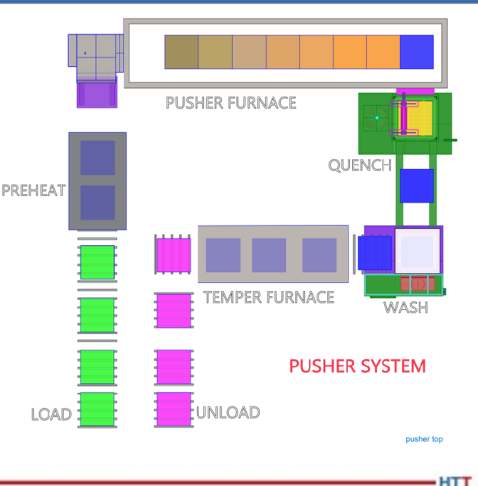
Diagram of a pusher furnace system.
MICHAEL MOUILLESEAUX: Here’s a pusher furnace system. Typically, but not always, pushers are put into a system because you have multiple operations that you must perform. This example is in a U-shape. The loading and unloading are next to each other. This could be a linear layout.
In another life, I worked for a company in Syracuse, New York that had 14 furnaces that were all linearly oriented. So, the person on the front of the furnace did one thing, the person on the back of the furnace did another thing, and they really didn’t communicate.
I, personally, am not a fan of that. I like this operation because you can have one or two people performing the loading and unloading operation, and you could have a furnace operator who would be responsible for the overall control of this piece of equipment.
You can see that we have four loads here that are in whatever way we chose to fixture them — baskets, fixtures, or whatever it might be. We’ve put a couple of parts in a preheat so we could perform that same cleaning that we talked about in preheating the load with low-cost BTUs. The preheat then goes into the vestibule, the loads progress down through the furnace as we described, you get to the end and that load is quenched. When the load comes out of the quench, just as in the batch furnace, it’s going to be 150–200°F plus. We want that to cool down to room temperature because the next operation is going to be washing.
After the load to cools down to room temperature, we then put it in the wash. Following the wash operation, you might have a drip station. So, whatever it was that you have washed off in the water, you don’t want that to go into the temper. Following the drip station, then you would go into the tempering furnace. Here we’re showing three positions; it could be three, it could be six, it could be nine. This is just an example.
Following the tempering operation, we would go out and in that first position, you might have a blower underneath and you would be circulating, room temperature air through it up into a duct work ahead and that’s how you would cool the room down to low temperature. Those loads would progress down that unload station so, at the very end, you are unloading the parts, perhaps for a subsequent shop blast cleaning operation or development of rust preventative or maybe they’re just put back into the customer’s container.
In a captive operation, they might go into a container where the parts would go on to a subsequent grinding or hard-turning operation.
This can be automated. Here you can see that the loads progress into the preheat, they progress through the furnace, they go into the quench, and they’re put into the wash. It’s quick.
Diagram of a pusher furnace load.
DOUG GLENN: Yes. It doesn’t happen this fast in real life, everyone!
MICHAEL MOUILLESEAUX: In the temper, the load exits the temper and goes into the unloading station. The point of this is to show that it progresses through the furnace.
The advantage is that you have relatively small loads that you’re processing, there is a very consistent process in the pusher furnace, and what you’re on for is that however you’ve designed this system, every load goes through every station. You don’t have an opportunity to easily extract a load as quenched and not wash it. It can be done. You could have a furnace designed to do that, but it’s not easy. After it’s washed, as you can see in this animation, typically it’s going to progress into the temper. Could you design a station that would allow you to offload it? You could, but normally that’s not how that’s done.
So, the load progresses through the temper and then you go in to where it is then subsequently unloaded.
If the batch furnace’s strong suit is the fact that it is extremely flexible — particularly in a “systemic” way — the pusher furnace’s strength is its productivity. °
DOUG GLENN: Yes, higher levels of productivity. But you’ve got to have, if not the same product, at least the same process on whatever it is you’re putting in there.
MICHAEL MOUILLESEAUX: Bingo. That’s exactly what you must have there, yes.
About the expert: Michael Mouilleseaux is general manager at Erie Steel LTD. Mike has been at Erie Steel in Toledo, OH since 2006 with previous metallurgical experience at New Process Gear in Syracuse, NY and as the Director of Technology in Marketing at FPM Heat Treating LLC in Elk Grove, IL. Having graduated from the University of Michigan with a degree in Metallurgical Engineering, Mike has proved his expertise in the field of heat treat, co-presenting at the 2019 Heat Treat show and currently serving on the Board of Trustees at the Metal Treating Institute.