Thirsting for knowledge about quenching, but not sure where to start? Heat TreatToday has coalesced technical information across articles and podcast episodes from key experts, including significant quenching methods, innovative developments with quenching, and how to control temperature during the process.
Discover more about these three topics in today’s Technical Tuesday original content feature.
Monitor Quench Temperatures with Unique Thermal Barrier Designs
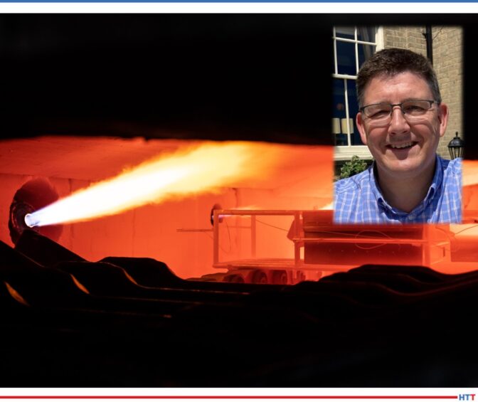
Automotive heat treating operations require repeatable operations to ensure that the composite parts within an automobile perform reliably. Steve Offley, also known as “Dr. O," the product marketing manager at PhoenixTM, outlines case studies of several temperature-critical operations to demonstrate how unique thermal barrier design for thru-process monitoring systems can solve temperature measuring problems. These processes include sealed gas carburizing into an integrated oil quench as well as LPC followed by transfer to a sealed high-pressure gas quench chamber.
Offley comments on the quenching process following LPC, saying, "During the gas quench, the [thermal] barrier [for temperature monitoring] needs to be protected from Nitrogen N2(g) or Helium He(g) gas pressures up to 20 bar." If you are facing heat treat processing with integrated quench, learn more about this temperature monitoring solution.
Intensive Quenching: An Answer for a "Greener" Heat Treat?
Gas furnaces have the potential to be a significant source of carbon emissions in many essential heat treat processes. However, an innovative approach combining induction through heating with intensive quenching could be one answer for greener heat treating, particularly for steel production.
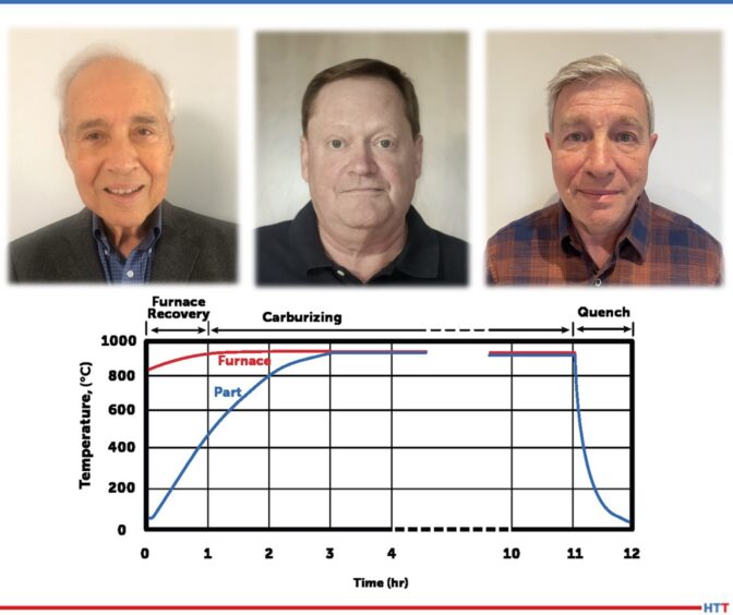
In this article, Chris Pedder,Edward Rylicki, and Michael Aronov share that an “ITH + IQ” technique "eliminates, in many cases, the need for a gas-fired furnace when conducting through hardening and carburizing processes." A lot of this comes down to shortening the time it takes to perform this process, but there is so much more that the authors illuminate in their tests and graphs.
Drinking from a Firehose: Answering Your Quench Questions with a Thorough Radio Review
Stay afloat in a sea of quenching tips with this Heat TreatRadio review, summarizing three recent podcast episodes centered around quenching tips, techniques, and training — especially applying to the auto industry.
Explore the "green" process of salt quenching with Bill Disler of AFC-Holcroft, the topic of water in your quench tank with Greg Steiger of Idemitsu Lubricants America, and a broad review of auto industry quenching with Scott MacKenzie of Quaker Houghton, Inc.
Thinking about travel plans for the upcoming holiday season? You may know what means of transportation you will be using, but perhaps you haven't considered the heat treating processes which have gone into creating that transportation.
Today’s Technical Tuesday original content round-up features several articles from Heat TreatToday on the processes, requirements, and tools to keep planes in the air and vehicles on the road, and to get you from one place to the next.
Standards for Aerospace Heat Treating Furnaces
Without standards for how furnaces should operate in the aerospace, there could be no guarantee for quality aerospace components. And without quality aerospace components, there is no guarantee that the plane you're in will be able to get you off the ground, stay in the air, and then land you safely at your destination.
In this article, written by Douglas Shuler, the owner and lead auditor at Pyro Consulting LLC, explore AMS2750, the specification that covers pyrometric requirements for equipment used for the thermal processing of metallic materials, and more specifically, AMEC (Aerospace Metals Engineering Committee).
This article reviews the furnace classes and instrument accuracy requirements behind the furnaces, as well as information necessary for the aerospace heat treater.
Dissecting an Aircraft: Easy To Take Apart, Harder To Put Back Together
Curious to know how the components of an aircraft are assessed and reproduced? Such knowledge will give you assurance that you can keep flying safely and know that you're in good hands. The process of dissecting an aircraft, known as reverse engineering, can provide insights into the reproduction of an aerospace component, as well as a detailed look into the just what goes into each specific aircraft part.
This article, written by JonathanMcKay, heat treat manager at Thomas Instrument, examines the process, essential steps, and considerations when conducting the reverse engineering process.
If you are one of the growing group of North Americans driving an electric vehicle, you may be wondering how - and how well - the components of your vehicle are produced. Electric vehicles (EVs) are on the rise, and the automotive heat treating world is on the lookout for ways to meet the demand efficiently and cost effectively. One potential solution is laser heat treating.
Explore this innovative technology in this article composed by Aravind Jonnalagadda (AJ), CTO and co-founder of Synergy Additive Manufacturing LLC. This article offers helpful information on the acceleration of EV dies, possible heat treatable materials, and the process of laser heat treating itself. Read more to assess the current state of laser heat treating, as well as the future potential of this innovative technology.
When the Rubber Meets the Road, How Confident Are You?
Reliable and repeatable heat treatment of automotive parts. Without these two principles, it’s hard to guarantee that a minivan’s heat treated engine components will carry the family to grandma’s house this Thanksgiving as usual. Steve Offley rightly asserts that regardless of heat treat method, "the product material [must achieve] the required temperature, time, and processing atmosphere to achieve the desired metallurgical transitions (internal microstructure) to give the product the material properties to perform it’s intended function."
TUS surveys and CQI-9 regulations guide this process, though this is particularly tricky in cases like continuous furnace operations or in carburizing operations. But perhaps, by leveraging automation and thru-process product temperature profiling, data collection and processing can become more seamless, allowing you better control of your auto parts. Explore case studies that apply these two new methods for heat treaters in this article.
A component supplier in the automotive industry has secured a multimillion-dollar contract to receive a turnkey automated nitrocarburizing furnace system for the production of electric passenger vehicle brake components.
Under the contract, Nitrex will design, manufacture, commission, and test continuous-line furnaces, part of the NXL furnace series, which are capable of processing millions of brake parts annually.
In addition to the furnace design, Nitreg®-C and ONC® technologies are integral to this order. This ferritic nitrocarburizing process with post-oxidation improves metal corrosion resistance and effectively reduces rust formation. It is designed to achieve lower non-effluent emissions associated with electric vehicle braking systems.
Furthermore, Nitrex will integrate QMULUS, an AI and machine learning IoT platform, to enhance the supplier’s manufacturing capabilities and drive continuous improvement throughout its operations.
"[This project] empower[s] our customers to thrive as the transition to electric vehicles and more advanced solutions accelerates,” expressed Nitrex CEO Jean-Francois Cloutier.
Find heat treating products and services when you search on Heat Treat Buyers Guide.com
Cuáles son las características más deseables de un probador de dureza Brinell? Esta reseña del equipo le permitirá evaluar si debe o no incorporarlo a su departamento de tratamiento térmico.
Read the Spanish translation of this article in the version below or read the English translation when you click the flag to the right. Both the Spanish and the English versions were originally published in Heat Treat Today's August 2023 Automotive Heat Treat print edition.
Toda empresa dedicada al tratamiento térmico deberá practicar ensayos de dureza, algunos de ellos utilizando la medición Brinell que data desde el año 1900, lo que lleva a que se amerite el análisis de tan perdurable técnica. La prueba en mención requiere de un penetrador de bola de carburo de tungsteno que impacte de manera vertical sobre la superficie del material a ser ensayado, previamente ubicado éste sobre un yunque fijo. Paso seguido, se mide el diámetro de la “huella” generada por la bola, mínimo por los ejes “x” y “y,” y se toma el promedio de estas mediciones como cifra operativa de la que se pueda valer el técnico para establecer la dureza, bien sea alimentando una ecuación o mediante la lectura de una tabla de valores en la que se relacione diámetro frente a dureza.
Contact us with your reader feedback!
Para el ensayo Brinell se dispone de una amplia gama de cargas de fuerza, al igual que de diámetros de penetradores, reflejando la gran variedad de metales a ser probados; no obstante, en la mayoría de ensayos se implementa una bola de 10mm bajo una carga de 3.000 kg. En las grandes máquinas de apoyo a suelo por lo general el penetrador es motorizado, aunque otras operan a partir de palancas y pesas, mientras que también las hay hidráulicas o neumáticas.
Existen tres razones principales por las que la prueba Brinell no deja de ser el método más opcionado para la medición de la dureza en muchas industrias de tratamiento térmico.
1. Preparación de la superficie
La preparación de la superficie de una muestra para las pruebas Brinell toma solo unos segundos con una amoladora. Siempre que la muestra esté firmemente asentada sobre el yunque presentando la cara superior en dirección perpendicular a la dirección de la fuerza del penetrador, de acuerdo a lo exigido por las normas, no es necesario lograr una superficie demasiado lisa.
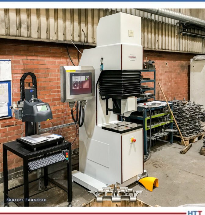
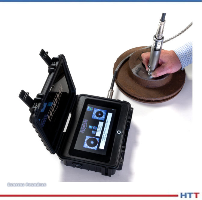
Figura 1. Robusto probador Brinell in situ
2. Contaminación de la superficie
Es poco probable que los contaminantes diminutos en una superficie generen una “prueba errónea” bajo un penetrador Brinell, a diferencia de la prueba de dureza Rockwell (el método más común en la industria). En esta prueba un pequeño indentador de diamante penetra menos de una centésima de pulgada, arrojando como resultado el que cualquier contaminante o anomalía en la superficie que pueda impedir o favorecer el progreso del penetrador (incluído el paralelismo) represente un problema, y obligando a que las muestras para la prueba Rockwell se deban preparar cuidadosamente antes de realizar la misma.
3. Portabilidad
Quizás el factor más significativo es que los robustos equipos portátiles de mano Brinell, con cabezales de prueba hidráulicos, permiten probar, in situ, piezas grandes, pesadas, de superficies rugosas o formas irregulares. Esta característica es de tal utilidad en la industria que ha motivado a que los órganos de normalización internacional otorguen una dispensación especial, una excepción si se quiere, a las máquinas portátiles, pese a que la ejecución de las mismas no sea susceptible de verificación directa como sí lo es la de sus equivalentes, las máquinas fijas.
Con fuerzas que van desde los 3000 kg hasta 1 kg, y bolas penetradoras tan pequeñas como 1 mm, las pruebas Brinell se pueden usar en una amplia gama de metales, pero los lugares en los que existiría la mayor probabilidad de encontrar un equipo de 10mm/3000kg son las forjas, las fundiciones, las plantas de tratamiento térmico, los laboratorios y las áreas de control de calidad. Previamente mencionamos que no se requiere que la superficie de las muestras de prueba sea absolutamente lisa; de hecho, es posible medir con un grado importante de precisión las superficies irregulares en materiales de configuración gruesa ya que el diámetro de la hendidura es tan grande en relación con cualquier irregularidad en la superficie.
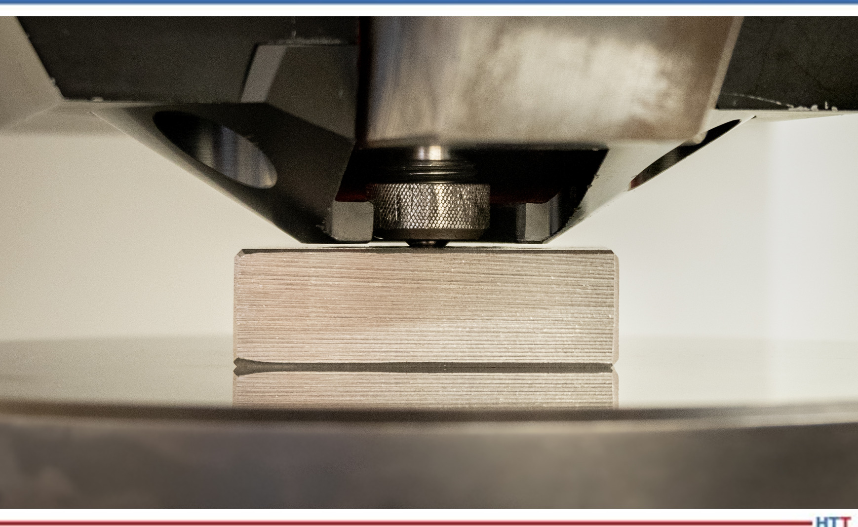
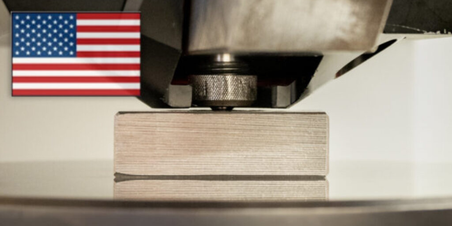
Figura 2. Probador de Brinell, grado calibrador, en primer plano
En la Figura 2 se puede apreciar cómo un probador Brinell de grado calibrador introduce la bola de carburo de tungsteno en la muestra de prueba. Se mantiene la bola en posición para estabilizar la deformación plástica.
Las normas que rigen de manera detallada las pruebas Brinell son la ASTM E-10 y la ISO 6506, pero el procedimiento práctico para los técnicos es muy sencillo, tanto que el entrenamiento no debería tardar más de una hora. Para ensayar piezas forjadas, palanquillas y otras muestras, una hendidura debería bastar aunque, desde luego, en ciertas aplicaciones de extrema importancia se podrá utilizar más de una para mayor seguridad.
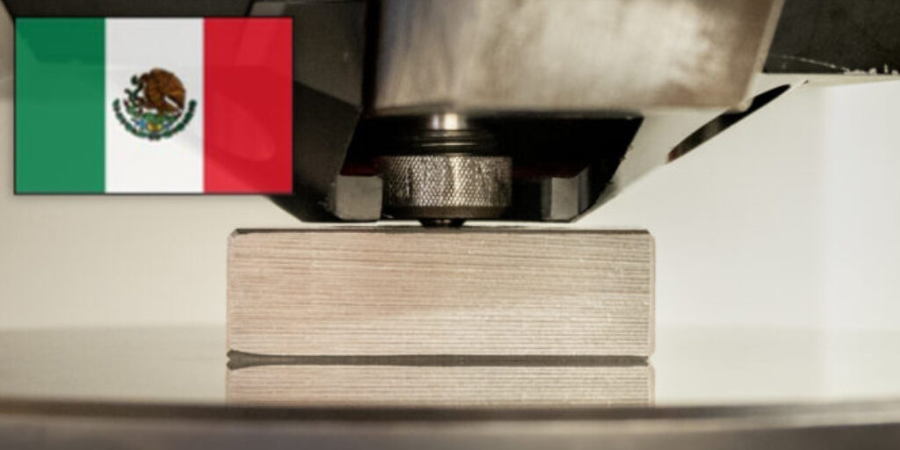
Saber si analizar o no cada muestra en un lote determinado deberá decidirse con base en la inconsistencia de las muestras mismas, más no responde a problemática alguna con las pruebas de Brinell en sí. En ciertas industrias se prueba cada pieza que se produce debido a que el riesgo de error es demasiado alto. Un buen ejemplo lo encontramos en la producción de los componentes de los eslabones para las orugas utilizadas en tanques y maquinaria pesada (retroexcavadoras y demás). Cada eslabón de cada oruga de un tanque en uso en el ejército británico ha sido probado por Brinell en una máquina totalmente automática, de alta velocidad, que cuenta con una poderosa abrazadera integral para mantener el componente absolutamente rígido durante la prueba. Por cierto, esa máquina es la de la primera foto. Con un cuidado adecuado y razonable, un probador Brinell robusto podrá generar cientos de miles de pruebas; de hecho, el probador de la Figura 1 ha realizado varios millones.
Las pruebas duran aproximadamente quince segundos ya que el penetrador se debe dirigir hacia el material de manera uniforme sin permitir la posibilidad de un “rebote” y evitando por completo llegar a golpear el material. Por otro lado, el metal debe recibir la presión por un período de tiempo suficiente que garantice que la hendidura se deforme de la manera más plástica posible, es decir, minimizando al máximo el riesgo de la más ligera contracción de la hendidura una vez retirado el penetrador.
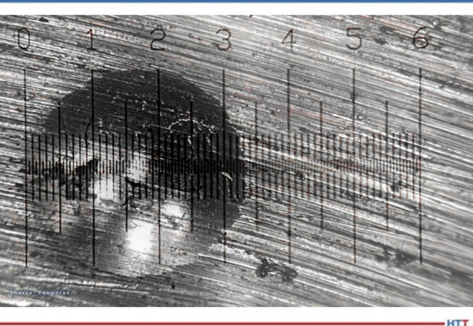
Figura 3. Medición de una hendidura de prueba de dureza Brinell
Sin embargo, es en este punto que se presentan las complicaciones. Después de generar cuidadosamente la hendidura y retirar la muestra de prueba de la “boca” de la máquina probadora, es necesario medir la hendidura en al menos dos diámetros. Dado que las hendiduras de Brinell tienen como máximo 6 mm de ancho y que una diferencia de 0,2 mm en el diámetro podría equivaler a 20 puntos de dureza, obtener la medición correcta es esencial y de alta complejidad. La mayoría de los técnicos usan un microscopio iluminado para lograrlo, pero aún así puede ser un desafío. Considere la Figura 3.
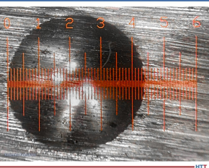
Los microscopios de medición manual han mejorado a lo largo de los años, y cuando se obtiene una hendidura relativamente “limpia” con una retícula nítidamente iluminada, se le puede facilitar al técnico experimentado realizar una medición precisa. La Figura 4 presenta un escenario menos complejo que el anterior pero, aun así, ¿cómo podemos saber si realmente se ha juzgado con precisión la posición del borde?
Figura 4. Medición con microscopio mejorado y retícula bien iluminada.
Al crearse la hendidura se genera un cordoncillo en el perímetro de la misma debido a que el metal no solo presiona hacia abajo, sino también hacia los lados. Este cordoncillo puede difi cultar la ubicación del punto en el que comienza realmente la hendidura, y tres técnicos diferentes pueden hacer fácilmente tres estimaciones diferentes de su lugar de inicio. Es esta variación en la interpretación de los resultados por parte de los operadores la que ha llevado a que, durante más de 80 años, la prueba Brinell se haya considerado un poco “ordinaria”, apta tal vez para el maquinista en el taller, pero de dudoso valor para el científi co en el laboratorio.
En 1982 llegó a los mercados el primer lector automático, siendo éste la culminación de años de investigación, y valiéndose de software privado que llevó a las computadoras de la época a sus límites. El equipo podía hacer cientos de mediciones de un lado a otro de la hendidura y calcular el diámetro medio en una fracción de segundo. Poco después llegó a ser parte integral de una máquina de prueba Brinell. La noticia de la aparición de este equipo pronto llegó a algunos usuarios importantes en la industria de las herramientas petroleras quienes exigieron a sus proveedores valerse de él; quince años más tarde se había diseminado ampliamente el uso de esta tecnología generando la transformación de la percepción que se tenía de la prueba Brinell. Podríamos decir que la prueba Brinell había llegado a la mayoría de edad.
Figura 5. La última versión de ese microscopio automático en acción
Desde luego, como con cualquier equipo de medición importante, la calibración y el mantenimiento regulares son aconsejables, si no obligatorios. Los fabricantes mismos suelen estipular un cronograma de mantenimiento que se debe tener en cuenta junto con las reglas de calibración establecidas por las agencias internacionales.
Al considerar las opciones para la prueba de dureza en muestras con tratamiento térmico, en última
instancia existen tres métodos: Brinell, Rockwell y Microdureza (Vickers o Knoop).
Pese a que no es adecuada para muestras muy pequeñas o demasiado delgadas, la prueba Brinell es relativamente “inmune” a los contaminantes pequeños, los penetradores no son costosos, y, gracias al ancho de la hendidura, las pruebas de superficies con acabado áspero e irregular no presentan dificultades. Con el desarrollo, hace 40 años, de la medición automática de la hendidura, se superó la única deficiencia grave de la prueba Brinell, proporcionando las garantías que tan vital importancia revestían para los proveedores de piezas esenciales en industrias de toda índole, incluídas las de petróleo y gas, aeroespaciales y de defensa y transporte.
Sobre el autor: Alex Austin se viene desempeñando desde 2002 como gerente de Foundrax Engineering Products Ltd. Foundrax es proveedor de equipos de prueba de dureza Brinell desde1948, siendo en realidad la única compañía en el mundo especializada en el campo.
Alex funge en el Comité de Prueba de Dureza por Hendidura ISE/101/05 del British Standards Institution. En su calidad de miembro de la delegación británica de la Organización Internacional de Normalización, ha aportado como consultor para el desarrollo de la norma ISO 6506 “Materiales metálicos–prueba de dureza Brinell” y preside en la actualidad la revisión ISO de dicha norma.
What are the most desirable attributes of a Brinell hardness tester? Does it belong in your heat treat department? Read this equipment overview to decide.
Read the English translation of this article in the version below or read the Spanish translation when you click the flag to the right. Both the Spanish and the English versions were originally published in Heat Treat Today's August 2023 Automotive Heat Treat print edition.
Alex Austin
Managing Director
Foundrax Engineering Products Ltd
Source: Foundrax
All heat treatment companies must test hardness; many with a Brinell tester. Existing since 1900, a review of this time-tested method is in order.
Contact us with your Reader Feedback!
The Brinell test requires a tungsten carbide ball indenter to be forced vertically into the surface of the test material, placed on a rigid anvil. The diameter of the indentation made by the ball is then measured across both its x and y axes as a minimum, and the average of these measurements is taken as the working figure. The technician can then either feed that figure into an equation to determine the hardness or read from a “diameter-to-hardness” chart.
There are various forces and indenter diameters available for Brinell testing reflecting the very wide range of metals that need to be assessed, but most tests involve a 10 mm ball under a 3,000 kg load. In large, floor standing machines, the indenter is usually motor-driven, but some machines use levers and weights, while others are hydraulic or pneumatic. The Brinell test remains the default method for hardness measurement in many heat treatment facilities, for three primary reasons.
1. Surface Preparation
Preparing the surface of a sample for Brinell testing takes just a few seconds with a grinder. Provided the sample is sitting steadily on the anvil and the top face of the sample is perpendicular to the direction of force of the indenter — as mandated by the standards — the surface does not need to be particularly smooth.
Figure 1. Heavy-duty Brinell tester in situ
2. Surface Contamination
Minute surface contaminants under a Brinell indenter are unlikely to cause a “mis-test.” By comparison, during Rockwell testing, the most widely used method across all industries, a tiny diamond indenter penetrates the surface by less than one hundredth of an inch, and any contaminants or surface abnormalities (including parallelism) that could impede or assist the progress of the indenter are a problem, which means that Rockwell samples must be carefully prepared before testing.
3. Portable
Perhaps most significant, rugged, hand-held portable Brinell testers with hydraulic test heads enable large, heavy, and awkwardly shaped components of rough surface finish to be tested in situ. This feature is of such utility in industry that the international standards authorities give a dispensation — a special designation — to portable machines, although their performance cannot be directly verified like their floor-standing cousins.
With forces ranging from 3000 kg down to 1 kg and indenter balls as small as 1 mm, Brinell testing can be used on a vast range of metal, but forges, foundries, heat treatment plants, quality control areas, and laboratories are the places one would most likely find a test machine working at 10 mm/3000 kg. It was mentioned earlier that the surface of test samples doesn’t need to be particularly smooth, in fact roughly- ground surfaces on materials with a coarse grain structure can be measured quite safely because the diameter of the indentation is so large relative to any irregularities on the surface.
Figure 2. Close-up of a calibration-grade Brinell tester
In Figure 2, a calibration-grade Brinell tester drives the tungsten carbide ball into the test sample. The ball is being held in position to stabilize plastic deformation. ASTM E-10 and ISO 6506 — the authoritative documents for Brinell testing — lay out standards in detail, but the practical procedure for workshop technicians is very straightforward; training should not take longer than an hour. When testing forgings, billets, and other samples, one indentation should suffice but in certain critical applications more than one indentation may be used for assurance.
The question of whether to test every sample in a batch will depend on how inconsistent those samples might be; it has nothing to do with any issues with Brinell testing itself. In certain industries, every single product is tested because the risk of failure is too high. A good example of this is the production of links for the tracks used on tanks and other armored vehicles. Every link in every tank track in use by the British Army has been Brinell tested on a high-speed, fully automatic machine that features a powerful integral clamp to keep the component rigid during the test. You can view the machine in Figure 1 on page 44. Subject to reasonable care, a heavy-duty Brinell tester will perform many hundreds of thousands of tests. The machine in Figure 1 has performed several million.
Tests take approximately fifteen seconds. The indenter must be driven uniformly into the material with no possibility of either a rebound or a speed that would “punch” the indenter into the material. Also, the metal must be loaded for a sufficient length of time to ensure the indentation is properly (plasticly) deformed, that is, the risk of an indentation shrinking very, very slightly after the indenter is withdrawn is kept to a minimum.
Figure 3. Measurement of Brinell hardness test indentation
Measuring the indentation is more challenging. After carefully making the indentation and withdrawing the test sample from the “jaws” of the test machine, one must measure the indentation across at least two diameters. Given that Brinell indentations are at most 6 mm across and that 0.2 mm difference in diameter might equal 20 hardness points, getting the measurement right is critical — and tricky. Most technicians will use an illuminated microscope to do this, but even then it can be a challenge. Consider Figure 3 on the next page.
Making an indentation leaves a “ridge” at the indentation perimeter because metal is not just pushed downwards, but also sideways. This ridge can obscure where the real indentation begins, and three different technicians can easily make three different estimates of where that is. And this variation in operators’ interpretation of results is why, for over 80 years, the Brinell test was seen as a little “rough and ready,” for the workshop machinist, perhaps, but probably not for the laboratory scientist.
Manual measurement microscopes have improved over the years, and a relatively “clean edged” indentation with a crisply illuminated graticule can be less challenging for the experienced technician to make an accurate measurement. Figure 4 is a less difficult scenario than the one above. Even so, how can we know if we have really judged the position of the edge precisely?
Figure 4. Measurement with improved microscope and well-illuminated graticule
In 1982, the first automatic reader hit the markets. This was the culmination of years of research and used proprietary software that pushed the computers of the day to their limits. The equipment could make hundreds of measurements across the indentation and calculate the mean diameter in a split second. Not long afterwards, it was available as an integral part of a Brinell test machine. Word of this equipment soon reached critical users in the oil tool industry, and they mandated its use to their suppliers. Within 15 years, the use of this technology was widespread and the perception of the Brinell test’s accuracy had been transformed. The Brinell test, in a sense, had come of age. See Figure 5 for the latest version of that automatic microscope in action.
Finally, like any important measuring equipment, regular calibration and servicing is desirable, if not compulsory. Manufacturers typically stipulate a service schedule which must be considered alongside the calibration rules dictated by international agencies.
When considering options for hardness testing of heat treated samples, there are ultimately three test methods: Brinell, Rockwell, and Microhardness (Vickers or Knoop).
Figure 5. Latest version of the automatic microscope in action
While Brinell testing isn’t suited to very small or very thin samples, it is relatively “immune” to small contaminants, the indenters are not expensive, and the width of the indentation means that testing of coarse grained and roughly finished surfaces is not problematic. With the development of reliable automatic indentation measurement, the one serious deficiency of the Brinell test was overcome, providing the assurance that was vital to critical components suppliers in all types of industries such as oil and gas, aerospace, defense, and transportation.
About the Author:
Alex Austin has been the managing director of Foundrax Engineering Products Ltd. since 2002. Foundrax has supplied Brinell hardness testing equipment since 1948 and is the only company in the world to truly specialize in this field. Alex sits on the ISE/101/05 Indentation Hardness Testing Committee at the British Standards Institution. He has been part of the British delegation to the International Standards Organization advising on the development of the standard ISO 6506 “Metallic materials – Brinell hardness test” and is the chairman and convenor for the current ISO revision of the standard.
For more information:
Contact www.foundrax.co/uk.
Find heat treating products and services when you search on Heat Treat Buyers Guide.com
The trend of automotive companies in recent years has been to bet on greener ways of transportation to reduce the carbon footprint that we have left over the last decades.
In today’s article, Humberto Torres Sánchez, quality coordinator at ZF Group makes the point that as heat treatment professionals, it is our duty to look for viable alternatives that do not affect the quality of heat treated products, remain safe, and above all reduce our carbon footprint. Read this original content release in Heat TreatToday’sAugust 2023 Automotive print edition.
Humberto Torres Sánchez
Quality Coordinator
ZF Group
Source: ZF Group
At ZF Group, we are committed to this challenge with many heat treat efforts employing induction. In fact, the decision to incorporate induction heat treatment initially was made to reduce operating costs, improve part and plant cleanliness, and improve layout, as opposed to conventional hardening. With induction heat treat, we are able to use less quench media — avoiding waste — and work to improve the efficiency of induction heat treatment in our facilities.
As a result, we’ve seen major improvements. These include streamlined processes by reducing electricity consumption, reduction of air emissions, and the most important, in my opinion, the total elimination of the use of oil for tempering when using environmentally friendly tempering media.
But improvements didn’t happen overnight. It took at least two years to fully incorporate induction for our automotive parts production, and streamlining the processes came about in stages. Three key steps to incorporate induction for our in-house heat treat operations were:
Achieve the metallurgical characteristics required by drawings and making use of the parameters of the inductor machine (e.g., power, heating speed, quench flow).
Validate the product with functional tests (dynamic and static).
To accommodate all of these new changes, we must add continuous training with personnel. This is essential to avoid reprocessing parts, as well as to reinforce the importance of analytical and critical thinking in favor of ecological improvement.
Another important element to move towards sustainable automotive processing solutions is employing the use of low pressure carburizing (LPC) instead of conventional carburizing. Greater homogeneity of metallurgical characteristics such as hardness and effective case depth can be achieved. Using LPC, we can reduce air emissions and eliminate quenching oil.
Making automotive heat treat operations environmentally friendly is an all encompassing endeavor.
Humberto Torres Sánchez
Making automotive heat treat operations environmentally friendly is an all encompassing endeavor. In transitioning away from oil quenchants in heat treat operations, we have been able to use cleaning detergents that are less corrosive, and which have a longer half-life within the process. In the future, the processes the industry uses will move to more environmentally friendly chemicals, and the correct preventive maintenance to avoid liquid leaks to eliminate soil contamination will be made.
Through all these efforts, ZF Group is committed to a greener mobile future.
About the Author: Humberto Torres Sánchez is the quality coordinator at ZF Group and is responsible for the quality department, laboratories, and special processes (heat treatment and welding). Involved in a variety of plant operations, he acts as the lead auditor for both CQI-9 and CQI-15. Learn more about Humberto from his 40 Under 40 Class of 2022profile.
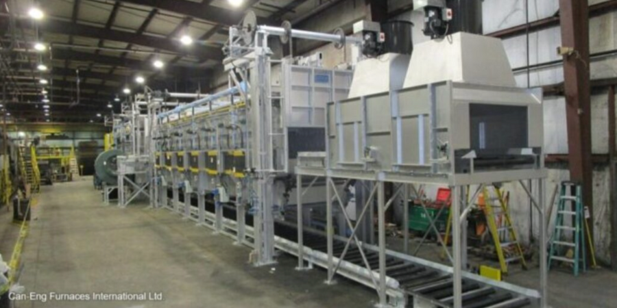
A roller hearth iso-thermal annealing line for steel automotive impression forgings is to be installed for a major American producer located in North Carolina.
The system comes from CAN-ENG Furnaces International Limited. It will be capable of both iso-thermal annealing and normalizing with a high temperature furnace operating under exothermic atmosphere. The line includes a separate low temperature roller hearth furnace, automatic bin dump and loading system, integrated tray/basket return system, and level II automation technology. The time frame for the heat treat line installation is in Q2, 2024.
Prior to the sale of this heat treat furnace, the furnace supplier had provided a mesh belt normalizing furnace, cast link belt normalizing furnace, and a roller hearth iso-thermal annealing furnace to the forgings producer.
Find heat treating products and services when you search on Heat Treat Buyers Guide.com
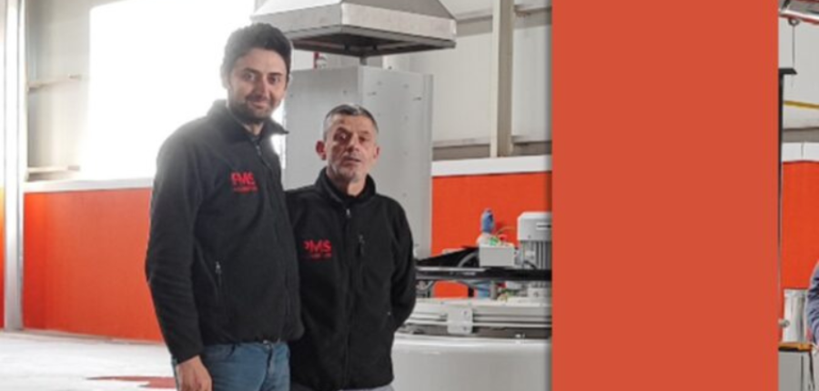
PMS Alüminyum, an aluminum extrusion company, has added a nitriding system from a North American based company that also has international locations to enhance its production capabilities and meet the increasing demand for high-quality, metal profiles across industries including automotive, construction, solar energy, defense, aerospace, and rail.
Previously outsourcing this process, PMS Alüminyum made the decision to bring nitriding operations in-house for streamlined logistics coordination, long-term cost savings, improved availability of ready-to-use dies, and faster turnaround times. Moreover, the growing number of dies to be treated made in-house processing a more viable and cost-effective solution.
The Nitrex pit-type furnace, model NX-1020, with Nitreg® controlled nitriding and Nitreg®-C controlled nitrocarburizing technologies, provides capabilities for processing H11 and H13 dies.
The system was installed in the extrusion company's new facility in November 2022 that also houses an extrusion press and powder coating lines.
Find heat treating products and services when you search on Heat Treat Buyers Guide.com
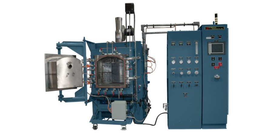
A retort furnace with an Inconel 602CA alloy retort has been shipped from Pennsylvania to a leading manufacturer of motor laminations, located in Midwestern U.S. The laminations are deployed for motors in various aerospace, military, automotive, medical and industrial fields.
L&L Special Furnace shipped the model XLC3348 XLC3348 which has an effective work zone of 23” x 23” x 36” and uniformity of ±15°F above 1,200°F. The control system includes one control loop along with six zones of heating volume that can be adjusted to achieve the required temperature gradients. The model XLC3348 satisfies all requirements for AMS2750F class 3 uniformity and type B instrumentation. The process gas lines are required copper refrigeration lines along with stainless steel to ensure a very low dew point in the process gasses.
Find heat treating products and services when you search on Heat Treat Buyers Guide.com
Piotr Skarbiński Vice President of Aluminum and CAB Products Segment SECOWARWICK Source: LinkedIn
EV/CAB lines for electric battery coolers' protective atmosphere brazing will be provided to manufacturers from Poland and the Czech Republic.
SECO/WARWICK Group's EV/CAB continuous lines are products dedicated to the automotive sector. EV/CAB solutions work for heat exchangers’ leading manufacturers and are used for mass production of large-size car battery coolers.
"Globally, the demand for electric cars and thus for battery coolers is increasing," commented Piotr Skarbiński, vice president of the Aluminum and CAB Products Segment, SECO/WARWICK Group. "It should be emphasized that the EV/CAB line is not a standard product, generally available on the market. Many years of experience have allowed us to create solutions optimally adapted to the production in this industry."
Find heat treating products and services when you search on Heat Treat Buyers Guide.com