Technical Tuesday

Heat Treaters, First Article Inspection, and AS9102 Compliance


Source: Paulo


Aerospace, automotive, medical and all other industries require FAI — first article inspection, the systematic inspection of new parts to ensure they’ll perform as designed. This includes parts that are subject to heat treatment, which adheres to its own process-specific set of FAI requirements.  This week’s Technical Tuesday feature provides an examination of the exhaustive FAI documentation process for heat treatment of aerospace parts and why it’s so critical.

“Heat treatment almost always distorts parts—it’s the price that comes with enhancing mechanical properties. First article inspections help heat treaters and customers determine whether specified processes will result in acceptable amounts of distortion or if design, material, manufacturing and processing specs need to change.” ~ Paulo


Read more: “First Article Inspections and AS9102 Compliance: How Heat Treaters Fit In”

Heat Treaters, First Article Inspection, and AS9102 Compliance Read More »

Temperature Monitoring and Surveying Solutions for Carburizing Auto Components: Introduction

This is the first in a 4-part series by Dr. Steve Offley (“Dr. O”), Product Marketing Manager at PhoenixTM, on the technical challenges of monitoring low-pressure carburizing (LPC) furnaces. This introductory article explains the LPC process and general monitoring needs and challenges. 


Carburizing Process

Dr. Steve Offley (“Dr. O”), Product Marketing Manager PhoenixTM

Carburizing has rapidly become one of the most critical heat treatment processes employed in the manufacture of automotive components. Also referred to as case hardening, it provides necessary surface resistance to wear while maintaining toughness and core strength essential for hardworking automotive parts.

The carburizing heat treatment process is commonly applied to low carbon steel parts after machining, as well as high alloy steel bearings, gears, and other components. Being critical to product performance, monitoring and controlling the product temperature in the heat treatment process is essential.

The carburizing process is achieved by heat treating the product in a carbon-rich environment, typically at a temperature of 900 – 1050 °C / 1652 – 1922 °F. The temperature and process time significantly influences the depth of carbon diffusion and associated surface characteristics. It is critical to the process that, following diffusion, a rapid quenching of the product is performed in which the temperature is rapidly decreased. This generates the microstructure giving the enhanced surface hardness while maintaining a soft and tough product core.

Increasing in popularity in the carburizing market is the use of batch or semi-continuous batch low-pressure carburizing furnaces. New furnace technology employs the dissociation of acetylene (or propane) to produce carbon in an oxygen-free low-pressure vacuum environment, which diffuses to a controlled depth in the steel surface. Following the diffusion, the product is transferred to a high-pressure gas quench chamber where it is rapidly gas cooled using typical N2 or Helium up to 20 bar.

An alternative to gas quenching is the use of an oil quench, used commonly in continuous carburizing furnaces where the products are plunged into an oil bath.


Fig 1: Schematics of the LPC Carburizing process showing the Temperature and Pressure steps

Temperature Monitoring Challenges in Low-Pressure Carburizing

As already stated, the success of the carburizing process is governed by careful control of both the process temperature and duration in the heating and quench stages. Obviously, when considering temperature, we are interested in the product temperature, not the furnace. Measuring product temperature through a carburizing process, although possible using trailing thermocouples, as performed historically, is neither easy nor safe, and it disrupts production for lengthy periods.

PhoenixTM provides a superior solution with the use of a “thru-process” temperature monitoring system. As the name suggests, the PhoenixTM temperature profiling system is designed to travel through the thermal process, measuring the product and or furnace environment from start to finish. The system can be incorporated into a standard production run so does not compromise productivity. A high accuracy, multi-channel data logger records temperature from thermocouple inputs, located at points of interest on, in, or around the product being thermally treated. To protect the data logger as it travels through the hostile furnace, a thermal barrier is employed to keep the logger at a safe working temperature to prevent damage and ensure accuracy of measurement. The barrier also obviously needs to protect during the quench, whether that be against high pressure or oil ingress if the quench can’t be avoided.

Employing the PhoenixTM system a complete thermal record of the product throughout the entire process can be collected. A popular enhancement to the system is the use of 2-way RF telemetry, providing real-time process monitoring directly from the furnace, useful for either profiling or performing a live Temperature Uniformity Survey (TUS). The product temperature can be viewed live and downloaded at any point in the furnace. Raw temperature data collected from the process can be converted into useful information using one of the custom-designed PhoenixTM Thermal View Software packages available. The thermal graph can be reviewed and analyzed to give a traceable, certified record of the process performance. Such information is critical to satisfying CQI-9, AMS2750, and other regulatory demands. Fully TUS-compliant reports can be produced in moments from the simple and intuitive software, making accurate TUS a simple and quick task. Information can be used to not only prove product quality but provide the means to confidently change process characteristics to improve productivity and process efficiency (Optimize Diffusion, Soak and Quench).

Temperature Monitoring and Surveying Solutions for Carburizing Auto Components: Introduction Read More »

Heat Treat Tips: Quenching

During the day-to-day operation of heat treat departments, many habits are formed and procedures followed that sometimes are done simply because that’s the way they’ve always been done. One of the great benefits of having a community of heat treaters is to challenge those habits and look at new ways of doing things. Heat Treat Today101 Heat Treat Tips, tips and tricks that come from some of the industry’s foremost experts, were initially published in the FNA 2018 Special Print Edition, as a way to make the benefits of that community available to as many people as possible. This special edition is available in a digital format here.

In today’s Technical Tuesday, we continue an intermittent series of posts drawn from the 101 tips. The category for this post is Quenching, and today’s tips–#8, #38, and #81–are from three different sources: Dan Herring,  “The Heat Treat Doctor®”, of The Herring Group; Combustion Innovations; and Super Systems, Inc. 


Heat Treat Tip #8

14 Quench Oil Selection Tips

Dan Herring,  “The Heat Treat Doctor®”, of The Herring Group

Here are a few of the important factors to consider when selecting a quench oil. 

  1. Part Material – chemistry & hardenability 
  2. Part loading – fixturing, girds, baskets, part spacing, etc. 
  3. Part geometry and mass – thin parts, thick parts, large changes in section size 
  4. Distortion characteristics of the part (as a function of loading) 
  5. Stress state from prior (manufacturing) operations 
  6. Oil type – characteristics, cooling curve data 
  7. Oil speed – fast, medium, slow, or marquench  
  8. Oil temperature and maximum rate of rise 
  9. Agitation – agitators (fixed or variable speed) or pumps 
  10. Effective quench tank volume 
  11. Quench tank design factors, including number of agitators or pumps, location of agitators, size of agitators, propellor size (diameter, clearance in draft tube), internal tank baffling (draft tubes, directional flow vanes, etc.), flow direction, quench elevator design (flow restrictions), volume of oil, type of agitator (fixed v. 2 speed v. variable speed), maximum (design) temperature rise, and heat exchanger type, size, heat removal rate in BTU/hr & instantaneous BTU/minute.
  12. Height of oil over the load 
  13. Required flow velocity through the workload 
  14. Post heat treat operations (if any) 

Submitted by Dan Herring,  “The Heat Treat Doctor®”, of The Herring Group.

Heat Treat Tip #38

Oil and Water Don’t Mix

Keep water out of your oil quench. A few pounds of water at the bottom of an IQ quench tank can cause a major fire. Be hyper-vigilant that no one attempts to recycle fluids that collect on the charge car.

Submitted by Combustion Innovations

Heat Treat Tip #81

Quench Oil Troubles

According to Super Systems, Inc., there are one of three problems to consider if your quench is just not cutting it. Although SSI focuses more on atmosphere control systems, when parts come out soft, the problem isn’t always the atmosphere – sometimes it’s the quench. Here are three things to consider regarding your quench:

  • First, check the composition of the quench media. Is it up to spec? Does it need to be refreshed?
  • Is the quench receiving adequate agitation to thoroughly quench the load?
  • Is the quench at the right temperature? If the bath is too warm when the load enters, quenching won’t go well!

Submitted by Super Systems, Inc.


Photo credit: Heat Treat Today FNA 2018; Super Systems, Inc.


If you have any questions, feel free to contact the expert who submitted the Tip or contact Heat Treat Today directly. If you have a heat treat tip that you’d like to share, please send to the editor, and we’ll put it in the queue for our next Heat Treat Tips issue. 

Heat Treat Tips: Quenching Read More »

Applying PID to Temperature Variances in Vacuum Furnaces


Source: Solar Manufacturing


Controlling process temperature with accuracy and without extensive operator involvement is a crucial task in the heat treat shop and calls for the use of a temperature controller, which compares the actual temperature to the desired control temperature, also known as the setpoint, and provides an output to a control element. This comparative process relies upon an algorithm, the most commonly used and accepted in the furnace industry being the PID, or Proportional-Integral-Derivative, control.

“This popular controller is used because of its robust performance in a wide range of operating conditions and simplicity of function once understood by the processing operator,” writes Real J. Fradette, a Senior Technical Consultant with Solar Atmospheres, Inc, and the author of “Understanding PID Temperature Control as Applied to Vacuum Furnace Performance” (with William R. Jones, CEO, Solar Atmospheres, Inc, contributing).

The PID algorithm consists of three basic components, Proportional, Integral, and Derivative which are varied to get optimal response. If we were to observe the temperature of the furnace during a heating cycle it would be rare to find the temperature reading to be exactly at set point temperature. The temperature would vary above and below the set point most of the time. What we are concerned about is the rate and amount of variation. This is where PID is applied. ~ Fradette

In this week’s Technical Tuesday, we direct our readers to Fradette’s article at Solar Manufacturing’s website where he and Jones cover the following on PID temperature controllers:

  • Definitions, e.g., Closed Loop System; Proportional (GAIN); Integral (RESET); and Derivative (RATE)
  • Actual operation of a PID temperature controller, including understanding PID dimensions and values; and general rules for manually adjusting PID
  • The art of tuning, a manual
  • Autotuning
  • Tweaking the furnace PID controller
  • and other factors


Read more: “Understanding PID Temperature Control as Applied to Vacuum Furnace Performance”

Photo credit

Applying PID to Temperature Variances in Vacuum Furnaces Read More »

The Workhorses of Industry: High-Strength, Heat-Treated Bolts & Fasteners


Source: Bayou City Bolt


A comparison of minimum tensile strength of heat-treated and non-heat-treated fasteners

One would be hard-pressed to find an industry that isn’t served by high-strength or heat-treated bolts and fasteners. They are required in the automotive, construction, transportation, marine, aerospace, oil & gas, petrochemical, and presses and molds manufacturing fields. In oil & gas and petrochemical manufacturing, for example, high-strength bolts and fasteners are necessary in order to achieve seal closure on flanged joints, fittings, and closures; withstand tensile stresses within the bolts; and provide the strength needed for bolts and pins to withstand forces from high horsepower equipment. You name the industry sector, and the manufacturing process will be just as dependent upon bolts and fasteners to answer the demands of the equipment, the process, and/or the application.

In this overview of the importance of heat treating in fastener and bolt production, Bayou City Bolt provides:

  • an explanation of the heat treating processes used depending upon the material and the application,
  • a comparison of the minimum tensile strength of heat-treated and non-heat-treated fasteners (see image to the right),
  • grade steels best used for heat treating fasteners and bolts,
  • the case hardening process, and
  • the proper use of hardened steel fasteners.

An excerpt:

“About 90 percent of fasteners are steel based and the required strength level is usually developed in steel fasteners using quenching and tempering processes. Accordingly, the terms “high strength” with “heat treated” or “hardened” are often equivocated with the fastener world. However, heat treatment includes a wide range of processes. Some heat treatments like annealing soften a metal, while others harden and strengthen.”


Read more: “Heat Treatment of Bolts & Fasteners”


The Workhorses of Industry: High-Strength, Heat-Treated Bolts & Fasteners Read More »

Heat Treat Tips: Induction Heating — Stuff You Should Know

During the day-to-day operation of heat treat departments, many habits are formed and procedures followed that sometimes are done simply because that’s the way they’ve always been done. One of the great benefits of having a community of heat treaters is to challenge those habits and look at new ways of doing things. Heat Treat Today101 Heat Treat Tips, tips and tricks that come from some of the industry’s foremost experts, were initially published in the FNA 2018 Special Print Edition, as a way to make the benefits of that community available to as many people as possible. This special edition is available in a digital format here.

In today’s Technical Tuesday, we continue an intermittent series of posts drawn from the 101 tips. The category for this post is Induction Heating, and today’s tips–#29, #73, and #83–are from Dr. Valery Rudnev, FASM, Fellow of IFHTSE, “Professor Induction”, Director of Science & Technology at Inductoheat Inc., an Inductotherm Group company. Dr. Rudnev is a regular contributor to Heat Treat Today


Heat Treat Tip #29

Induction Heating Non-Ferrous Metals & Alloys

Dr. Valery Rudnev, FASM, Fellow IFHTSE, Professor Induction, Director Science & Technology, Inductoheat Inc., an Inductotherm Group company

Steel components by far represent the majority of hot worked and heat-treated parts for which electromagnetic induction is used as a source of heat generation. At the same time, many other non-ferrous metals and alloys are also inductively heated for a number of com­mercial applications. Induction heating of low electrically resistive metals such as Al, Mg, Cu, and others typically require using lower electrical frequencies compared to carbon steels, cast irons, or high resistive non-magnetic metals (such as Ti or W, for example) and metallic alloys. The lower value of electrical resistivity results in smaller current penetration depth (depth of heat source gen­eration), making it possible to apply much lower frequencies without facing the danger of eddy current cancellation.

Heat Treat Tip #73

Induction Hardening Powder Metal

When induction hardening powder metallurgy (P/M) materials, it is good practice to have a minimum density of at least 7.0 g/cm3 (0.25 lb/in.3). This will help obtain consistent induction hardening results. When hardening surfaces that have cuts, shoulders, teeth, holes, splines, slots, sharp corners, and other geometrical discontinuities and stress risers, it is preferable to have a minimum density of 7.2 g/cm3 (0.26 lb/in.3). Low-density P/M parts are prone to cracking due to a penetration of the gases into the subsurface areas of the part through the interconnected pores. Interconnected pores contribute to decreased part strength and rigidity compared with wrought materials. In addition, the poor thermal conductivity of porous P/M parts encourages the development of localized hot spots and excessive thermal gradients and also requires the use of quenchants with intensified cooling rates to obtain the required hardness and case depths. This is so because an increase in pore fraction and a reduction in density negatively affect the hardenability of P/M materials compared to their wrought equivalents.

Heat Treat Tip #83

Induction Hardening Cast Iron

Induction hardening of cast irons has many similarities with hardening of steels; at the same time, there are specific features that should be addressed. Unlike steels, different types of cast irons may have similar chemical composition but substantially different response to induction hardening. In steels, the carbon content is fixed by chemistry and, upon austenitization, cannot exceed this fixed value. In contrast, in cast irons, there is a “reserve” of carbon in the primary (eutectic) graphite particles. The presence of those graphite particles and the ability of carbon to diffuse into the matrix at temperatures of austenite phase can potentially cause the process variability, because it may produce a localized deviation in an amount of carbon dissolved in the austenitic matrix. This could affect the obtained hardness level and pattern upon quenching. Thus, among other factors, the success in induction hardening of cast irons and its repeatability is greatly affected by a potential variation of matrix carbon content in terms of prior microstructure. If, for some reason, cast iron does not respond to induction hardening in an expected way, then one of the first steps in determining the root cause for such behavior is to make sure that the cast iron has not only the proper chemical composition but matrix as well.


These tips were submitted by Dr. Valery Rudnev, FASM, Fellow IFHTSE, Professor Induction, Director Science & Technology, Inductoheat Inc, an Inductotherm Group company.


If you have any questions, feel free to contact the expert who submitted the Tip or contact Heat Treat Today directly. If you have a heat treat tip that you’d like to share, please send to the editor, and we’ll put it in the queue for our next Heat Treat Tips issue. 

Heat Treat Tips: Induction Heating — Stuff You Should Know Read More »

Sacrificial Lambs: Hardness Testing and Heat Treating


Source: Gear Technology


Charles D. Schultz, president of Beyta Gear Service

In a recent blog post at Gear Technology, Charles D. Schultz, president of Beyta Gear Service, addressed the importance of accuracy when describing hardness test location and the reason why “sacrificial lambs” are needed during production.

“I cannot emphasize enough that if you are not cutting up parts or coupons you do not know what is really happening during your thermal processing.” ~ Charles D. Schulz


Read more: “Gear Materials: More Inside Heat Treating Trivia”

Photo Credit: Gear Technology

Sacrificial Lambs: Hardness Testing and Heat Treating Read More »

Heat Treat Tips: Burner Tuning & Calibration – It’s Not Your BBQ Grill . . .

During the day-to-day operation of heat treat departments, many habits are formed and procedures followed that sometimes are done simply because that’s the way they’ve always been done. One of the great benefits of having a community of heat treaters is to challenge those habits and look at new ways of doing things. Heat Treat Todays 101 Heat Treat Tips, tips and tricks that come from some of the industry’s foremost experts, were initially published in the FNA 2018 Special Print Edition, as a way to make the benefits of that community available to as many people as possible. This special edition is available in a digital format here.

In today’s Technical Tuesday, we continue an intermittent series of posts drawn from the 101 tips. The category for this post is Combustion, and today’s tip is #23.


Combustion

Heat Treat Tip #23

Burner adjustment to nominal gas and air ratios is a typical component of your combustion equipment maintenance. However, this process cannot be minimized in importance as any adjustment can affect operation, efficiency, exhaust emissions & equipment life. Factors to consider and address during any burner adjustment:

  • Burner adjustment should always be done when possible at normal furnace operating temperature under typical production to maintain best conditions for final calibration.
  • Provide clean combustion air: maintain blower filter & consider the source of any plant air.
  • An increase of gas may not increase power to the system due to heat transfer or throughput issues.
  • A decrease in combustion air will not create a hotter flame or add power to the system as this may only create a gas-rich operation resulting in reduced power and CO in the exhaust.
  • Verify gas & combustion supply pressures & consider creating a monthly log of incoming pressures.
  • While a visual inspection of flame can help to verify operation or proper combustion, burner gas /air adjustment can not accurately be performed by simply looking at color or size of a flame.
  • A working understanding of burner system is important to determine and verify values to gas/air and excess O² to a specific application.

This tip was submitted by WS Thermal.


If you have any questions, feel free to contact the expert who submitted the Tip or contact Heat Treat Today directly. If you have a heat treat tip that you’d like to share, please send to the editor, and we’ll put it in the queue for our next Heat Treat Tips issue. 

Heat Treat Tips: Burner Tuning & Calibration – It’s Not Your BBQ Grill . . . Read More »

Tackling the Hard-ness of Hardness Testing


Source: Struers.com


Hardness testing in heat treating has evolved to a precision science necessary to provide reliability in resolving yield strength of metal materials and to assist in comparing property differences of two materials, ultimately determining “the success or failure of a particular heat-treatment operation” (Daniel Herring, “Common Pitfalls in Hardness Testing,” Gear Solutions Magazine).

According to Herring, “The Heat Treat Doctor®” (see his Heat Treat Today consultant’s page here), “Hardness testing is thought to be one of the easiest tests to perform on the shop floor or in the metallurgical laboratory, but it can be one of the hardest tests to do properly.”

Today’s Best of the Web feature offers an easy-to-follow primer on this hard testing process, providing the following:

  • Definition of Hardness Testing
  • How Hardness Tests Work
  • Selecting the Best Hardness Test Method
  • The Four Most Common Indentation Hardness Tests: their uses, suitability, and distinctives
  • How to Ensure Accuracy and Repeatability in Hardness Testing
  • Surface Preparation Requirements for Hardness Testing
  • Definition of Hardness Testing Loads
  • Indent Spacing
  • Troubleshooting for Hardness Tests

For a teaser, consider this excerpt from the article from Struers:

Factors that influence hardness testing

A number of factors influence hardness tests results. As a general rule, the lower the load you use in the hardness test, the more factors that need to be controlled to ensure an accurate conclusion of the hardness test. 

Here are a few of the most important factors to consider to ensure an accurate conclusion from a hardness test.

  • External factors such as light, dirt, vibrations, temperature, and humidity should be controlled
  • The tester and stage should be secured on a solid horizontal table, and the sample should be clamped or held in a holder or anvil
  • The indenter should be perpendicular to the tested surface
  • Illumination settings should be constant during the test when using Vickers, Knoop, or Brinell
  • The tester should be recalibrated/verified every time you change the indenter or objective lens


Read more: “Hardness Testing Is a Key Element in Many Quality Control Procedures and R&D Work”

Photo credit: Struers

Tackling the Hard-ness of Hardness Testing Read More »

Heat Treat Tips: Atmosphere Control

During the day-to-day operation of heat treat departments, many habits are formed and procedures followed that sometimes are done simply because that’s the way they’ve always been done. One of the great benefits of having a community of heat treaters is to challenge those habits and look at new ways of doing things. Heat Treat Today‘s 101 Heat Treat Tips, tips and tricks that come from some of the industry’s foremost experts, were initially published in the FNA 2018 Special Print Edition, as a way to make the benefits of that community available to as many people as possible. This special edition is available in a digital format here.

Today, we begin an intermittent series of Technical Tuesday posts of the 101 tips by category, starting with Atmosphere Control


Atmosphere Control

Heat Treat Tip 5

Out of Control Carburizing? Try This 11-Step Test

When your carburizing atmosphere cannot be controlled, perform this test:

  1. Empty the furnace of all work.
  2. Heat to 1700°F (926°C).
  3. Allow endo gas to continue.
  4. Disable the CP setpoint control loop.
  5. Set generator DP to +35°F (1.7°C).
  6. Run a shim test.
  7. The CP should settle out near 0.4% CP.
  8. If CP settles out substantially lower and the CO2 and DP higher, there’s an oxidation leak, either air, water or CO2 from a leaking radiant tube.
  9. If the leak is small the CP loop will compensate, resulting in more enriching gas usage than normal.
  10. Sometimes but not always a leaking radiant tube can be found by isolating each tube.
  11. To try and find a leaking radiant tube, not only the gas must be shut off but combustion air as well.

Submitted by AFC-Holcroft

Heat Treat Tip 13

Finding the Cause for Bad Parts

So you just ran a batch and the parts are bad. Now what? According to Jim Oakes at Super Systems Inc., here is a good checklist to use to start isolating the problem. While not exhaustive, this list can at least take you through a progression of steps to help start identifying the culprit.

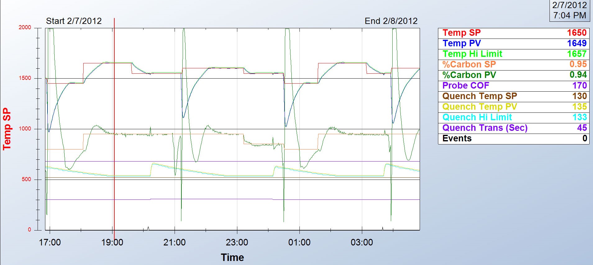
Step 1:  Review the process data for abnormalities. Did the setpoint for temperature and atmosphere get set properly? Does the process chart show good control of the temperature and atmosphere? Was the time at heat correct? Was the quench and temper processes run properly?

Step 2:  Check the generator to make sure it was pumping out the right atmosphere.

Step 3:  Check the furnace atmosphere. Even if the generator is working, there may be leaks in the furnace.

Step 4:  Check carbon controller to make sure it matches furnace atmosphere reading. Verify probe accuracy and adjust carbon controller.

Step 5:  Do probe troubleshooting. And if all else fails . . .

Step 6:  Replace the probe or call Super Systems for help.

Submitted by Super Systems Inc.

Heat Treat Tip 49

What to Do When Parts Are Light on Carbon

Many factors can contribute to why parts are not meeting the correct hardness readings. According to Super Systems Inc., here is a quick checklist of how to start narrowing down the culprit:

  1. Review process data for abnormalities: The first thing to do is make sure the parts were exposed to the right recipe. Check the recorders to make sure the temperature profile and atmosphere composition were correct. Make sure all fans and baffles were working correctly. Determine if any zones were out of scope and that quench times were acceptable. If any red flags appear, hunt down the culprit to see if it may have contributed to soft parts.
  2. Check the generator. Next, check the generator to make sure it is producing the gas composition desired for the process. If available, check the recorders to make sure the gas composition was on target. If not, check the generator inputs and then the internal workings of the generator.
  3. Check the furnace atmosphere. If the generator appears to be working correctly, the next step would be to check the furnace itself for atmosphere leaks. Depending on what type of furnace you have, common leak points will vary; for continuous furnaces, common leak points are a door, fan, T/C, or atmosphere inlet seals. Other sources of atmosphere contamination may be leaking water cooling lines in water-cooled jackets or water-cooled bearings. More than likely, if the generator is providing the correct atmosphere but parts are still soft, there is a leak into the furnace. This will often be accompanied by discolored parts.
  4. Check carbon controller to make sure it matches furnace atmosphere reading (verify probe accuracy and adjust carbon controller). This can be done using a number of different methods: dew point, shim stock, carbon bar, 3 gas analysis, coil (resistance), etc. Each of these methods provides a verification of the furnace atmosphere which can be compared to the reading on the carbon controller. If the atmosphere on the carbon controller is higher than the reading on the alternate atmosphere check, that would indicate the amount of carbon available to the parts is not as perceived. The COF/PF on the carbon controller should be modified to adjust the carbon controller reading to the appropriate carbon atmosphere. If the reading is way off, it may require the probe to be replaced.
  5. Check the carbon probe.
  6. Replace the probe – CALL SSI.

Submitted by Super Systems Inc.

Heat Treat Tip 62

Double Check Carbon Potential Control

Configuring your atmosphere controller to ensure the correct carbon potential readings can sometimes be tricky. We suggest you double check your atmosphere control settings to make sure they are set up correctly. Before making a change to the carbon controller, make sure the atmosphere that the carbon probe and carbon controller are reading is matching up to an alternate method of atmosphere. This can be done using a number of different methods: dew point, shim stock, carbon bar, 3 gas analysis, coil (resistance), etc. Each of these methods provides a verification of the furnace atmosphere which can be compared to the reading on the carbon controller. The COF/PF on the carbon controller should be modified to adjust the carbon controller reading to the appropriate carbon atmosphere.

It is important to make sure that the alternate method of verifying atmosphere is done properly (sampling ports, time for atmosphere exposure, sample prep, etc).

The calculation of carbon in the atmosphere using a carbon/oxygen probe is based on the output millivolts — created based on the partial pressure of oxygen in the reference air versus partial pressure of oxygen in the furnace, the temperature of the furnace, and a calculation factor referred to as COF (CO Factor), PF (Process Factor), or Gas Factor.

The carbon controller can be modified so the COF/PF value can be changed to match up with the alternate reading. A furnace calculator on the SSI website or mobile app can help determine what these settings should be. It is important to note that you should not change these values to the point where you are masking another issue such as a bad probe or a furnace/generator issue.

Again, if the reading is way off (a setting of a COF below 130, for example), it may require the probe to be replaced.

Submitted by Super Systems Inc.

Heat Treat Tip 75

Carbon Probe Trouble Shooting

If you’re having atmosphere problems with a furnace that has been operating normally for some time, avoid the temptation to remove the carbon probe. There are several tests you can run on nearly all carbon probes while the probe is still in the furnace, at temperature, in a reducing atmosphere. Super Systems Inc. provides an 11-step diagnostic procedure in a white paper on their website, in a paper titled, “Carbon Sensor Troubleshooting” by Stephen Thompson.

Submitted by Super Systems Inc.


Heat Treat Tip 88

Slight Positive Pressures Are Best

Atmosphere furnace pressure should be only slightly above ambient. The range should be between 0.25 – 0.35 inches water column. Higher pressures in multiple zone pusher furnaces will cause carbon control issues. High pressures in batch furnaces will cause high swings when doors and elevators move.

Submitted by AFC-Holcroft

Heat Treat Tip 94

Confirm Composition of Endothermic Atmosphere

Wisdom dictates a trust-but-verify approach to your endothermic generator. Although your generator is supposed to crank out a consistent endo atmosphere, we suggest periodically verifying the integrity of that atmosphere with a dewpoint analyzer or a 3-gas analyzer. Generator control systems provide control of air gas ratio and possibly a trim system, used to maintain a dew point that could be rich (too much gas) or lean (too much air). The dew point range could typically be between 30°F and 50°F. Flowmeters are provided to maintain a base ratio (2.7 : 1) for the air/gas mixture supplied to a retort filled with nickel-coated catalyst. The gas is then passed through an air cooler (some older systems used water) to freeze the reaction so the gas can be transported through a header system to furnaces. The ratio at which the gas is generated offers a dew point that can be measured. The makeup of the endothermic gas provided by a generator is typically 40% hydrogen, 40% nitrogen, and 20% carbon monoxide. Maintaining these percentages will result in a carburizing atmosphere that is conducive to best carburizing practices.

Non-dispersive infrared analyzer (NDIR) systems are invaluable when trying to troubleshoot generator issues. The analyzer will typically measure CO, CO2, and CH4. As mentioned earlier, if we know that 20% CO is being generated, we can cross check the air/gas ratio and sticking flow meters, or determine that an adjustment of the air and/or gas ratio is required. The measurement for indication of sooted or nickel depleted catalyst can also be achieved by using an analyzer. If the indicated measurement of CH4 is higher than .5%, a burnout of the catalyst is required, using the manufacturer’s required procedures. If after a burnout the CH4 level is still high, the catalyst may need to be replaced altogether.

Submitted by Super Systems Inc.  


If you have any questions, feel free to contact the expert who submitted the Tip or contact Heat Treat Today directly. If you have a heat treat tip that you’d like to share, please send to the editor, and we’ll put it in the queue for our next Heat Treat Tips issue. 

Heat Treat Tips: Atmosphere Control Read More »