Technical Tuesday

Prevent Catastrophic Fuel-Delivery Accidents: On Valve Safety Trains in Heat Treating Equipment

Robert Sanderson, PE, Rockford Systems, LLC

This article on the critical role of valve safety trains in the prevention of catastrophic fuel-delivery accidents at heat treating facilities is authored by Robert Sanderson, P.E., Director of Business Development in the Combustion Safety division of Rockford Systems, LLC, based in Rockford, Illinois. Valve safety trains require regular inspections, maintenance, and training.


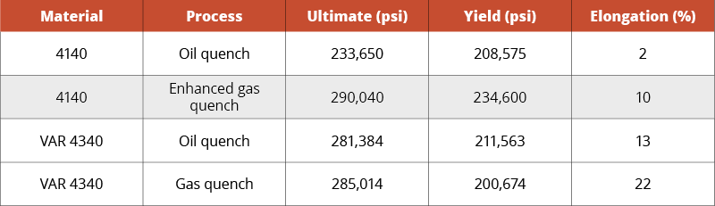
Heat treating, a thermal process used to alter the physical, and sometimes chemical, properties of a material or coating, is a high-temperature operation that involves the use of heating or chilling, normally to extreme temperatures, to modify a material’s physical properties — making it harder or softer, for example. Applications for heat treating are virtually endless, but at the heart of all thermal processes is the valve safety train.

These fuel-delivery devices maintain consistent conditions of gasses into furnaces, ovens, dryers, and boilers, among others, making them crucial in assuring safe ignition, operation, and shutdown. Equally important, they keep gas out of the system whenever equipment is cycled or shut off.

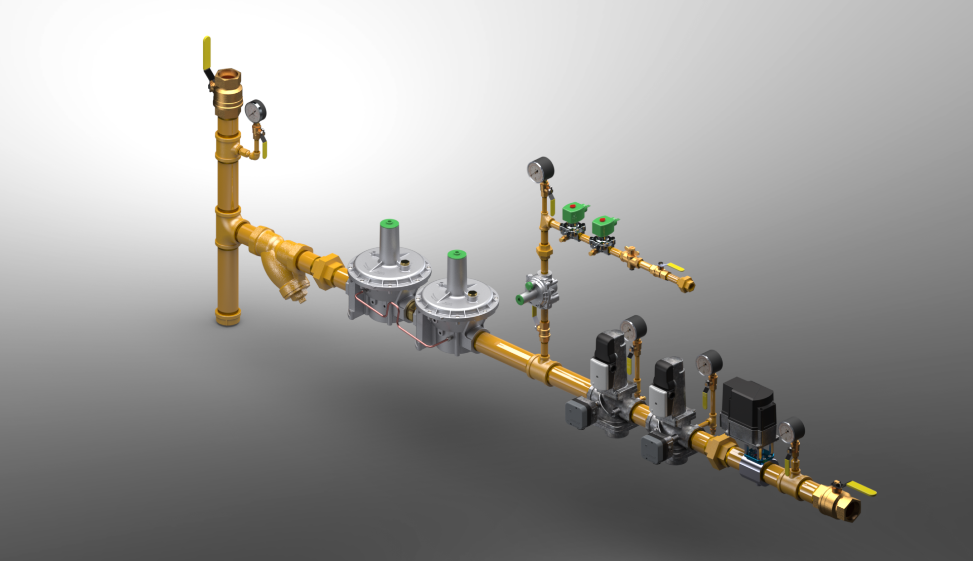
A valve safety train isn’t a single piece of equipment. Instead, it has many components including regulators, in-line strainers (“sediment traps”), safety shut-off valves (SSOV), manual valves (MV), pressure switches, and test fittings logically linked to a burner management system.

Flame-sensing components make sure that flames are present when they are supposed to be, and not at the wrong time. Other components may consist of leak-test systems, gauges, and pilot gas controls. At a minimum, there are two crucial gas pressure switches in a valve safety train, one for low pressure and one for high pressure. The low gas pressure switch ensures the minimum gas pressure necessary to operate is present. As you would assume, it will shut off fuel to the burner if the gas pressure is below the setpoint. The high gas pressure switch ensures excessive pressure is not present. It too will shut off fuel if the gas pressure is too high. Both switches must be proven safe to permit operation. Additionally, there will be an air pressure switch to ensure sufficient airflow is present to support burner operation.

Some systems have supplementary pressure switches, such as a valve-proving pressure switch. Switches such as these are typically used to enhance safety or provide other safety aspects specific to that application’s needs. A multitude of sensors within the valve safety train — pressure switches, flame detectors, position indicators — and isolation and relief valves work together in concert to prevent accidents.

Valve safety trains must be compliant with all applicable local and national codes, standards, and insurance requirements. The most common of these for North America are NFPA, NEMA, CSA, UL, FM. Annual testing and preventive maintenance are not only an NPFA requirement, but also oftentimes required by insurance agencies, equipment manufacturers, and national standards, including ANSI, ASME, and NEC.

Set Your Trap

The primary function of a valve safety train is to reliably isolate the inlet fuel from the appliance. Safety shut-off valves are purposely selected to do this. To protect these valves, the initial section of a safety train is used to condition the fuel and remove debris that could potentially damage or hinder all downstream safety components.

The first conditioning step is a sediment trap (a.k.a. dirt leg, drip leg). This trap captures large debris and pipe scale and provides a collection well for pipe condensates. The proper orientation of a sediment trap is at the bottom of a vertical feed. This downwards flow arrangement promotes the capture of debris and condensate into the trap. A horizontal feed across a sediment trap is an improper application. The second conditioning step is a flow strainer or filter element. These devices are fine particulate sieves. The removal of fine particulates from the fuel stream further protect the downstream safety devices from particulate erosion and abrasion. Taken together these conditioning steps remove particulates and condensates that might block, hinder, erode, or otherwise compromise the safety features of the downstream devices.

The Explosive Force of a Bomb

Owing to the presence of hazardous vapors and gases, a poorly designed or inadequately maintained safety train can lead to catastrophic accidents, ranging from explosions and fires to employee injuries and death. When this explosive force is unleashed, the shock wave carries equipment, debris, materials, pipes, and burning temperatures in all directions with tremendous force.

The following incidences provide just a few examples of why it is important to purchase the highest quality valve safety train and to keep it professionally maintained, inspected, and tested.

  • In 2018, a furnace explosion at a Massachusetts vacuum systems plant killed two men and injured firefighters as a result of fuel malfunction.
  • In Japan, an automobile manufacturer lost tens of millions of dollars when it was forced to shut down production for nearly a month after a gas-fueled furnace exploded due to flammable fumes building up in the tank.
  • In a Wisconsin bakery, an employee was seriously injured when he ignited an oven’s gas and was struck by a door that was blown off. A malfunctioning valve had allowed natural gas to build up inside the oven.
  • In 2017, a van-sized boiler exploded at a St. Louis box company, killing three people and injuring four others. The powerful, gas-fueled explosion launched the equipment more than 500 feet into the air.
  • In 2016, a boiler explosion in a packaging factory in Bangladesh enveloped the five-story building in flames, killing 23 people.

Two Dangers: Valves and Vents

Valves are mechanical devices that rely upon seats and seals to create mechanical barriers to control flow. Over time, these barriers wear out for a variety of

Glassblowing Furnace with Pipes

reasons, whether it is age, abrasion, erosion, chemical attack, fatigue or temperature. Increased wear contributes to leaks, and leaks lead to failures and hazards. Defective valves can allow gas to leak into a furnace even when the furnace is not in operation. Then, when the furnace is later turned on, a destructive explosion could occur.

Testing a valve’s integrity is an evaluation of current barrier conditions and may be used to identify a valve that is wearing out prior to failure. As such, annual valve leakage tests are an important aspect of a safety valve train inspection program. Along with annual testing, valves should be examined during the initial startup of the burner system, or whenever the valve maintenance is performed. Only trained, experienced combustion technicians should conduct these tests.

Improper venting is another danger. Here is the problem: Numerous components in a valve safety train require an atmospheric reference for accurate operation. Many of these devices, however, can fail in modes that permit fuel to escape from these same atmospheric points. Unless these components are listed as “ventless,” vent lines are necessary. Vent lines must be correctly engineered, installed, and routed to appropriate and approved locations. In addition, building penetrations must be sealed, pipes must be supported, and the vent terminations must be protected from the elements and insects. In short, vent lines are another point of potential failure for the system.

Even when vent lines are properly installed, building pressures can vary sufficiently enough that they prevent optimal burner performance. Building pressures often vary with seasonal, daily weather, and manufacturing needs, further complicating matters. Condensate in vent lines can collect and drain to low points or into the devices themselves. Heating, cooling, and building exhausters are known to influence building pressures and device responses, but so can opening and closing of delivery doors for shipping and receiving. Hence a burner once tuned for optimal operation might not be appropriately tuned for the opposite season’s operation.

The smart alternative to traditional vented valve trains is a ventless system that will improve factory safety and enhance burner operation. Ventless systems reference and experience the same room conditions where the burners are located, resulting in more stable year-round operating conditions, regardless of what is happening outside. Additionally, ventless designs typically save on total installation costs, remove leaky building penetrations, eliminate terminations that could be blocked by insects, snow or ice, improve inspection access, and ensure a fail-safe emergency response.

Final Thoughts

Valve safety trains are critical to the operation of combustion systems. Despite being used daily in thousands of industrial facilities, awareness of their purpose and function may be dangerously absent because on-site training is minimal or informal. To many employees on the plant floor, this series of valves, piping, wires, and switches is simply too complex to take the time to understand. What is known can be dangerously misunderstood.

Understanding of fuel-fired equipment, especially the valve safety train, is necessary to prevent explosions, injuries, and property damage. The truth is, although valve safety trains are required to be check regularly, they are rarely inspected, especially when maintenance budgets are cut. And while codes require training, they offer very little in terms of specific directions.

As a safety professional, the onus is on you. You and your staff must have a core level of knowledge regarding safe practices of valve safety trains, even if a contractor will be doing the preventive maintenance work. Most accidents and explosions are due to human error and a lack of training when an unknowing employee, for example, attempts to bypass a safety control. Preventive maintenance is essential to counter equipment deterioration, as is the documentation of annual inspection, recording switch set points, maintaining panel drawings, and verifying purge times. Accidents happen when this type of documentation is not available. Don’t wait for a near-miss or accident to upgrade your valve safety train.

Prevent Catastrophic Fuel-Delivery Accidents: On Valve Safety Trains in Heat Treating Equipment Read More »

Temperature Control System Improves Precision, Efficiency on Heat Treat Equipment: A Case Study

A century-old producer of die forgings recently needed to improve the process controls on its heat treating furnaces.

With process controls well over 10 years old, Clifford-Jacobs turned to Conrad Kacsik to improve its temperature process control system. The company, which serves a number of industries, including energy, aerospace, construction, mining, forestry, and rail, was eager to improve its temperature process control system, particularly because the incumbent system was producing inconsistent work.

The Challenge

Bud Kinney, Vice President of Innovation and Technology at IMT Corporation

Clifford-Jacobs was not getting consistent, repeatable results from its furnaces. The company also wanted more efficient and automated processes with data acquisition and electronic operating capability.

“We looked at a number of controls companies throughout the Midwest and interviewed them to learn about their experience with system controls and data acquisition,” said Bud Kinney, Vice President of Innovation and Technology at IMT Corporation, the parent of Clifford-Jacobs. “We knew we wanted an integrated system so we started looking at companies that did that as a matter of course. Most companies are limited to traditional controls, but Conrad Kacsik has a lot of experience doing the exact type of job we needed.”

Increasing Demands

Clifford-Jacobs makes forged parts for a variety of clients. Although forging does not generally require as much precision as other types of processes, customers are increasingly demanding, said Kinney.

“We believe that sooner rather than later things like Nadcap will come into forging, and our customers are very interested in us being able to demonstrate that our processes are always in control, even forge heating,” Kinney said. “This project helps ensure that we meet those needs. We couldn’t track things like set-point input values before. That’s another element we wanted to manage.”

The System

Retrofitting Clifford-Jacobs heat treating system.

Conrad Kacsik built a full process temperature control system that includes SCADA software from SpecView. They were able to retrofit the system on Clifford-Jacobs’ existing 16 furnaces, saving the company considerable expense and time. The temperature process control system uses Watlow F4T controllers paired with SpecView SCADA software, which allows for programming jobs/recipes, remote operation, secure (password protected) operation of furnaces and accurate automatic temperature recording. Conrad Kacsik also added alert lights that allow the operators to quickly see the status of each furnace from the shop floor.

H2: Benefits of Temperature Control System Integration

Clifford-Jacobs has noted several beneficial results from the new temperature control system. These include:

  • Increased accuracy. The new system runs each recipe exactly and records the results. The company can also control which employees can adjust temperature settings, preventing operators from rushing jobs with a higher temperature or inadvertently setting the furnace incorrectly.
  • Higher efficiency. With preprogramming, each furnace is always at the exact temperature it needs to be for the given task. An automatic preheat setting also safely prepares the furnace for the workday—eliminating downtime or the need to send an employee in early to start the furnaces.
  • More speed. Clifford-Jacobs can pre-program any recipe it needs, allowing for highly accurate and fast running of complex processes.
  • More convenience. Clifford-Jacobs can operate their furnaces from anywhere with an internet connection, or via an iPad used by an approved employee.
  • Precision for the future. The new system can be part of a Nadcap-approved process should the need arise. The SpecView software and advanced controllers automatically record each job and retain all data for verification.

The Results

“We used to have to use all kinds of resources to provide oversight on temperature control,” said Kinney. “This has given us a heating strategy. We write the recipes we want and just select from those. In addition to that, we know exactly what every furnace is doing at all times.”

The company is also pleased with the increased efficiency. They only heat product when they are ready to run production, and the furnace only uses the exact energy needed for each recipe. They are also saving on staffing, as they used to have to schedule people to ensure the furnace was at the right temperature.

“With this system, we can develop recipes for each part we make, which is both convenient and precise. It’s doing exactly what we expected it to do,” said Kinney.

Temperature Control System Improves Precision, Efficiency on Heat Treat Equipment: A Case Study Read More »

Temperature Monitoring and Surveying Solutions for Carburizing Auto Components: AMS2750E and CQI-9 Temperature Uniformity Surveys

Dr. Steve Offley (“Dr. O”), Product Marketing Manager PhoenixTM

This is the final installment in a 4-part series by Dr. Steve Offley (“Dr. O”) on the technical challenges of monitoring low-pressure carburizing (LPC) furnaces. The previous articles explained the LPC process and explored general monitoring needs and challenges (part 1), the use of data loggers in thru-process temperature monitoring (part 2), and the thermal design challenge (part 3). In this segment, Dr. O discusses AMS2750E and CQI-9 Temperature Uniformity Surveys. You can find Part 1 here, Part 2 here, and Part 3 here


A significant challenge for many heat treaters is the need to provide products certified to either AMS27150 (aerospace) or CQI-9 (automotive). To achieve this accreditation, furnace Temperature Uniformity Surveys (TUS) must be performed at regular intervals to prove that the furnace set-point temperatures are both accurate and stable over the working volume of the furnace. Historically, the furnace survey has been performed with great difficulty trailing thermocouples into the heat zone. Although it’s possible in a batch process when considering a semi-batch or continuous process, this is a significant technical challenge with considerable compromises as summarized below.

Trailing Thermocouple TUS Process Steps

Figure 1. Typical TUS thermocouple. Positions — 9 point survey. Furnace void corners and center
  • TUS is often carried out using long or ‘trailing’ thermocouples that exit through the furnace door.
  • Furnace often needs to be cooled, then de-gassed so TUS frame can be set up in the furnace.
  • Thermocouples are then led out through the furnace door and connected to a data logger or chart recorder.
  • The furnace is then heated to surveying temperatures.
  • The survey is then carried out, after which furnace is cooled, and thermocouples are removed.


Disadvantages of Traditional TUS Process

  • Lots of furnace downtime may be involved (can be up to 24 hours).
  • Thermocouples have to exit the furnace door.
    • This may involve “wedging” the door up, or “grooving” out the hearth to get thermocouples out.
    • Or thermocouples may get caught in the furnace door.
  • A significant amount of the technician’s time is taken up preparing report.

Applying the “Thru-Process” approach to TUS, the measurement system is transferred into the furnace with the survey frame allowing the setup process to be done quickly, safely, and repeatable. (See Figure 2)

Figure 2. PhoenixTM System loaded into a furnace as part of a TUS frame. Thermocouples pre-fitted to the 8 vertices of the cube frame and center. Furnace ambient temperature recorded either with a virgin exposed junction thermocouple (typical MI) or with heat sink damper fitted.

Operating the system with RF telemetry, TUS data is transferred directly from the furnace back to the monitoring PC where at each survey level temperature stabilization and temperature overshoot can be monitored live with TC and logger correction factors applied. The Thermal View Software is developed to ensure that the final TUS report complies fully to the AMS2750E/CQI-9 standards.

Figure 3. PhoenixTM Thermal View Survey Software showing a TUS profile at three set survey temperatures. The probe map shows exactly where each probe is located and easy trace identification. Detailed TUS report generated with efficiency.

Features incorporated into the Thermal View Software to provide full TUS capability include the following:

TUS Level Library – Set-up TUS level templates for quick efficient survey level specification (Survey Temp °F, Tolerance °F, Stabilization, and Survey Times)

TUS Frames Library – Show clearly exact TUS frame construction and probe location using Frame Library Templates – Frame Center and 8 Vertices.

Logger Correction File – Create a logger correction file to compensate TUS readings automatically from the logger’s internal calibration file.

Thermocouple Correction File – Create the thermocouple correction file and use to compensate TUS readings directly.

TUS Result Table & Graph View – For each TUS temperature level, see from the graph or TUS table instantaneously full survey results.

Furnace Class Reporting – Report the specified furnace class at each temperature level.


Overview

The PhoenixTM Temperature Profiling System provides a versatile solution for both performing product temperature profiling and furnace TUS in industrial heat treatment. It is designed specifically for the technical challenges of low-pressure carburizing (LPC) whether implementing either high-pressure gas quench or oil quench methodology, providing the means to Understand, Control, Optimize and Certify the LPC Furnace and guarantee product quality and process operation efficiency and certification.


Temperature Monitoring and Surveying Solutions for Carburizing Auto Components: AMS2750E and CQI-9 Temperature Uniformity Surveys Read More »

Dr. Valery Rudnev on . . . Equipment Selection for Induction Hardening: Continuous and Progressive Hardening, Part 2

This article continues the ongoing discussion on Equipment Selection for Induction Hardening by Dr. Valery Rudnev, FASM, IFHTSE Fellow. Dr. Rudnev previously reviewed equipment selection for scan hardening in three parts. The first part on equipment selection for continuous and progressive hardening is here; the third part is here. To see the earlier articles in the Induction Hardening series at Heat Treat Today as well as other news about Dr. Rudnev, click here


Frequency Selection

Depending on the application specifics, continuous and progressive hardening lines may use the same frequency for various in-line coils. In other cases, power levels and frequencies may be different at different heating positions. The presence of three general process stages (described in Part 1) makes a marked impact on a selection of process parameters and the design of an induction system.

When using different frequencies for the various heating stages, the coil design may need to change as well (e.g., a number of coil turns may need to be adjusted for load matching purpose). Just as the eddy current penetration depth in the heated part is affected by the frequency, the current flow in the inductor is affected as well. The wall thickness of the inductor turns (i.e., copper tubing wall) might need to be adjusted to accommodate different frequencies to maximize the coil electrical efficiency.¹

The wall thickness of an inductor’s heating face should be increased as frequency decreases. It is highly desirable for the current-carrying copper wall thickness to be 1.6 times greater than the current penetration depth in the copper (δCu). Increased kilowatt losses in the copper, which are associated with reduced electrical efficiency and greater water-cooling requirements, will occur if the wall is thinner than 1.6∙δCu. In some cases, the copper wall thickness can be noticeably thicker than the recommended value of 1.6∙δCu. This is because it may be mechanically impractical to use a tubing wall thickness of, for example, 0.25 mm (0.01 in.).

As an example, Figure 1 shows a number of continuous in-line multi-coil systems for induction heat treating wire products.²

Several continuous in-line systems for heat treating wire products (Courtesy of Radyne Corp., and Inductotherm Heating & Welding, UK. Both are Inductotherm Group companies.)

There are noticeable benefits of compact induction systems compared to fluidized beds, infrared heaters, and gas furnaces, such as quick response and the ability to provide a rapid change in the process operating parameters to accommodate the required temperature of the wire/cable being processed at speeds up to 5 mps. Frequencies that are in the range of 10 to 800 kHz are commonly applied. A dual-frequency concept can be beneficial to enhance electrical efficiency of while heating different diameters/thicknesses or it can be advantageous for through heating of metallic alloys that exhibit low toughness/high brittleness.

According to the dual-frequency concept, a lower frequency is used during the initial heating stage when the steel is magnetic. In the final heating stage, when the steel becomes nonmagnetic with significantly increased current penetration depth δsteel and becomes substantially more ductile, it is beneficial to use a higher frequency.

Case study¹:

As an example, consider the induction heating of a 1/8 inch-diameter (3.2 mm-diameter) steel rod from ambient to 2000°F (1100°C) using both a single 10-kHz frequency and dual 10-kHz/200-kHz frequencies (see Figure 2). When using the single frequency of 10 kHz (Figure 2, left), the rod’s final temperature experiences very little change regardless of the coil power that is increased more than fivefold (from 17 to 90 kW). The only noticeable difference is related to the initial slope of the temperature-time curve, where the steel is ferromagnetic. Upon reaching the Curie point, there is no noticeable temperature rise. This is the result of severe eddy current cancellation making the steel rod transparent (practically speaking) to the electromagnetic field of the induction coil.

Illustration of the dual-frequency concept when induction heating a 1/8 inch-diameter (3.2 mm-diameter) carbon steel rod from room temperature to 2012°F (1100°C) using both a single frequency of 10 kHz (a) and dual frequencies of 10 kHz/200 kHz (b). (Source: V.Rudnev, Systematic analysis of induction coil failures, Part 11c: Frequency selection, Heat Treating Progress, January/February, ASM Intl., 2008, pp. 27–29.)

In contrast, Figure 2, right, shows that a dual-frequency approach provides a remarkable improvement in the ability to heat the rod above the Curie temperature. A power of 14 kW/10 kHz was used to heat the rod below the Curie point and a power of 19 kW/200 kHz was used above it. The total required power is only 33 kW, compared with 90 kW using just 10 kHz, which was still unable to provide the required temperature rise.

Note: The target temperature of 2000°F (1100°C) is above typical target temperatures when hardening plain carbon or low alloy steels and it is more suitable for hot forming applications. This temperature was selected here to better illustrate a dual-frequency concept and the importance of avoiding eddy current cancellation when choosing operating electrical frequencies. It should be noted though that it is not unusual that the heat treating protocols/recipes for some alloyed steels and stainless steels may require target temperatures of 1900°F to 2100°F (1050°C to 1150°C) range.

In some not too often cases, three frequencies may be used. Lower frequency is applied for preheating inductors, a medium frequency is used for mid-heat inductors, and a high frequency is used for final heat inductors.

Sometimes, it is required that the induction system should be able to heat a variety of sizes using a single frequency. In these cases, in order to provide efficient steel heating, it is necessary to choose a frequency that will guarantee that the “diameter-to-current penetration depth (δsteel)” ratio exceeds 3.6 for any workpiece diameter or heating stage. Thus, it is important to remember that when calculating δsteel, the values of electrical resistivity and relative magnetic permeability of the heated material should correspond to their values at the highest temperature that occurs during the entire heating cycle.

The next installment of this column will review a variety of styles of inductors used in continuous and progressive induction hardening applications.


References

  1. V.Rudnev, D.Loveless, R.Cook, Handbook of Induction Heating, 2nd Edition, CRC Press, 2017.
  2. J.Mortimer, V.Rudnev, D.Clowes, B.Shaw, “Intricacies of Induction Heating of Wires, Rods, Ropes, and Cables”, Wire Forming, Winter, 2019, p.46-50

Dr. Valery Rudnev, FASM, IFHTSE Fellow, is the Director of Science & Technology, Inductoheat Inc., and a co-author of Handbook of Induction Heating (2nd ed.), along with Don Loveless and Raymond L. Cook. The Handbook of Induction Heating, 2nd ed., is published by CRC Press. For more information click here.

Dr. Valery Rudnev on . . . Equipment Selection for Induction Hardening: Continuous and Progressive Hardening, Part 2 Read More »

Heat Treat Control Panel: Best Practices in Digital Data Collection, Storage, Validation

When processing critical components, heat treaters value and demand precision in every step of the process — from the recipe to data collection — for the sake of accurate performance of the furnace, life expectancy of all equipment, as well as satisfactory delivery of a reliable part for the customer.

So what’s the obstacle to achieving those goals? Gunther Braus of dibalog GmbH/dibalog USA Inc. says, “The general problem is the human.” Indeed, the need to remove the variable of human fallibility plays a significant role in the search and development of equipment that could sense, read, and record data separate from any input from the operator. “As long there is a manual record of values there is the potential failure,” adds Braus.

Now, as part of the quest for precision, particularly in the automotive and aerospace industries, many control system requirements are driven by the need to prove process compliance to specified industry standards like CQI-9 and AMS 2750. These standards allow for and frequently require digital data records and digital proof of instrumentation precision.

With this in mind, Heat Treat Today asked six heat treat industry experts a controls-related question. Heat Treat Control Panel will be a periodic feature so if you have a control-related question you’d like addressed, please email it to Editor@HeatTreatToday.com and we’ll put your question to our control panel.

Q: As a heat treat industry control expert, what do you see as some of the best practices when it comes to digital data collection and storage and/or validation of instrumentation precision?

We thank those who responded: Andrew Bassett of Aerospace Testing & Pyrometry, Inc.; Gunther Braus, dibalog GmbH/dibalog USA Inc; Jim Oakes of Super Systems, Inc; Jason Schulze, Conrad Kascik Instrument Systems, Inc.; Peter Sherwin, Eurotherm by Schneider Electric; and Nathan Wright of C3Data.

Calibration and Collection

Jim Oakes (Super Systems Inc.) starts us off with an overview of the equipment review process, the crucial component of instrument calibration, and digital data collection:

“Industry best practices are driven by standards defined by the company and customers they serve. Both the automotive and aerospace industries have a set of standards which are driven through self-assessments and periodic audits. Instrument precision is defined by the equipment’s use and is required to be checked during calibrations. The frequency of these calibration depends on the instrument and what kind of parts and processes it is responsible for.

The equipment used for these processes can be defined as field test instrumentation, controllers, and recording equipment. Calibration is required with a NIST-traceable instrument that has specific accuracy and error requirements. Before- and post-calibration readings are required (commonly identified as “as found” and “as left” recordings). During calibration, a sensitivity check is required on equipment and is recorded as pass/fail. The periodic calibration procedure is carried out not only on test equipment but also on control and recording equipment, to ensure instrument precision.

Digital data collection is a broad term with many approaches in heat treatment. As mentioned, requirements are driven by industry standards such as CQI-9 and AMS 2750. Specifically when it comes to digital data collection, electronic data must be validated for precision; checked; and calibrated periodically as defined by internal procedures or customer standards. Data must be protected from alteration, and have specific accuracy and precision. Best practice tends to be plant wide systems that cover the electronic datalogging that promotes ease of access to current and historical data allowing use for quality, operational, and maintenance personnel. Best practices in many cases are defined by the standards within each company, but the hard requirements are often the AMS 2750 and CQI-9 requirements for digital data storage.”

Industry Guidelines and Requirements

Andrew Bassett (Aerospace Testing & Pyrometry) has provided us with a reminder of the industry guidelines for aerospace manufacturing (via AMS-2750E, paragraph 3.2.7.1 – 3.2.7.1.5)

  1. The system must create electronic records that cannot be altered without detection.
  2. The system software and playback utilities shall provide a means of examining and/or compiling the record data, but shall not provide any means for altering the source data.
  3. The system shall provide the ability to generate accurate and complete copies of records in both human readable and electronic form suitable for inspection, review, and copying.
  4. The system shall be capable of providing evidence the record was reviewed – such as by recording an electronic review, or a method of printing the record for a physical marking indicating review.
  5. The system shall support protection, retention, and retrieval of accurate records throughout the record retention period. Ensure that the hardware and or software shall operate throughout the retention period as specified in paragraph 3.7.
  6. The system shall provide methods (e.g., passwords) to limit system access to only individuals whose authorization is documented.

“One of the biggest issues I see with one of these requirements will be point 5,” says Bassett. “The requirement is to be able to review these records throughout the retention period, which in some instances is indefinite. I always recommend to clients who may be upgrading or purchasing new digital systems that they should consider keeping a spare system in place to be able to satisfy this requirement. Who knows — today we are working on Windows 10, but in 50 years, will our successor be able to go back and review heat treat data when everything is run on Windows 28?”

Jason Schulze, Aerospace Heat Treating“This is a topic that yields great discussions,” adds Jason Schulze (Conrad Kascik). He directs us to a challenge he sees from time to time.

Within the Nadcap AC7102/8 checklist, there is this question: “Do recorder printing and chart speeds meet the requirements of AMS 2750E Table 5 or more stringent customer requirements?” This correlates with AMS2750E, page 12, paragraph 3.2.1.1.2 “Process Recorder Print and Chart Speeds shall be in accordance with Table 5”.

“To ensure the proper use of an electronic data acquisition unit used on furnaces and ovens, these requirements must be understood,” continues Schulze. “Because this system is electronic, it should be designated a digital instrument and not an analog instrument. In doing so, this helps determine what requirements apply in Table 5. The only remaining requirement in Table 5 for digital instruments is ‘Print intervals shall be a minimum of 6 times during each time at temperature cycle. Print intervals shall not exceed 15 minutes.’

With this in mind, it is important to realize that, if your time at temperature cycles are short cycles (such as vacuum braze cycles), the sample rate of data collection may need to be adjusted to ensure it is recorded 6 times during the cycle.

As an example, if the shortest cycle processed is 4 minutes at temperature, a sample rate of every 60 seconds would not conform to AMS2750E because, in theory, the maximum amount of recordings would be 4 times during the time at soak. Now, if the sample rate was modified to every 30 seconds, this would allow ~8 recordings during the time at soak, which then would be conforming to AMS2750E.

Within the realm of electronic data acquisition on furnaces/ovens, this seems to be a frequent challenge for suppliers.”

A Critical Variable: Process Temperature

Nathan Wright (C3Data) agrees and zeroes in on process temperature as a critical variable to be measured:

“No matter the heat-treating process being carried out, complying with AMS-2750 and/or CQI-9 requires that the heat treater measure, record, and control several different variables. One of the more common variables that must be measured, recorded, and controlled is process temperature.

Measuring process temperatures requires the use of a precise measurement system (Figure-1 below), and the accuracy of said measurement system must be periodically validated to ensure its ongoing compliance.”

“The validation process is carried out through a series of pyrometric tests (Instrument Calibration and SAT), and historically these validation processes are highly error-prone.

In order to help ensure process instrumentation, process temperatures, and any other variable that impacts quality is properly validated it is good practice to begin automating compliance processes whenever and wherever possible. C3 Data helps automate all furnace compliance processes using software.”

A “Standard” Mindset

Gunther Braus (dibalog) chimes back in with some pertinent wisdom: “It is not sufficient only to record, you must live the standards like CQI-9, AMS, Nadcap or even your own standard you have set up, so you must survey the data. However, in the old times, there was a phrase: the one who measures, measures crap. In the end, it is all about surveillance of the captured data.

Where you store the data is a question of philosophy: personally, I prefer local storage in-house. Yes, we all talk about IOT, etc., and I do not want to start a discussion about security; it is more about accessing the data. No internet, no data. So simple. We are overly dependent upon cloud usage on the internet.

The automation of the instrumentation precision is so much effort in terms of automated communication between testing device and controller, from my point of view we are not there yet.”

A Look at the Standards In and Outside the Industry

Interesting question! writes Peter Sherwin (Eurotherm by Schneider Electric).

The aim is to record the true process temperature seen by the components being treated. However, there are many practical factors that can alter the accuracy of the reading. From the position of the thermocouple (TC), the TC accuracy (over time), suitability of the lead or extension wire, issues with CJC errors and instrument accuracy as well as electrical noise impacting the stability of the reading.

The standards do a good job to help by prescribing the location of TC, accuracies required for both TC and instrument, and frequent checks over time through TUS and SAT checks but note the specification requirements are maximum “errors”. And if you truly want to reach world-class levels of process control and reap the inherent benefits of better productivity and quality, you should aim to be well inside those tolerances allowed.

With 30yrs+ of data required to be stored (in certain cases, particularly aerospace), there should be some thought as to how and what form this should be stored in. There are many more options of storage when the data is in digital format.

  • Paper is very costly to store and protect.
  • The virgin data file should be secure and tamper-resistant and identical copies made for backup purposes held offsite.
  • The use of FTP is becoming more common to move files automatically from the instrument to a local server (with its own backup procedures to ensure redundant records in case of disaster).
  • Regular checks should be made to examine the availability and integrity of these electronic records.
  • Control and Data Instrument suppliers should ideally have many years of supplying instrument digital records with systems that can access even the earliest of data record formats.

We also look outside of the heat treat standards for truly best practices. The FDA regulation 21CFRPart11 and associated GAMP Good Automated Manufacturing Practice have been extended with the new document “Data Integrity and Compliance with Drug cGMP, Questions and Answers, Guidance for Industry”. These updates leverage A.L.C.O.A to describe the key principles around electronic records (see below). This industry is also leading the requirement for sFTP a more secure format of the FTP protocol.


Heat Treat Today will run this column regularly featuring questions posed to and answered by industry experts about controls. If you have a question about controls and/or data as it pertains to heat treating, please submit it to doug@heattreattoday.com or editor@heattreattoday.com.

Heat Treat Control Panel: Best Practices in Digital Data Collection, Storage, Validation Read More »

Combining Strength, Ductility in Alloys Using Enhanced Property Treatments


Source: Paulo


One of the rules in metallurgy is: “As strength increases, ductility decreases.”

What if it were possible to combine both strength and ductility in the same material? This is the challenge that a team of metallurgists took on at a leading heat treating company located in Willoughby, Ohio, starting with tests that compared enhanced property 4140 steel to vacuum arc re-melted (VAR) 4340 steel.

When all was said and done, Paulo Heat Treating, Brazing and Metal Finishing “developed a family of enhanced property processes that allow manufacturers to replace costly high-performance materials with much more cost effective 4140 steel.”

“Manufacturers could save time and money if lower-cost materials like 4140 exhibited the enhanced mechanical properties of VAR 4340 or other similar alloys.

It motivated us to develop a family of processes that would overcome one of metallurgy’s general rules: As strength increases, ductility decreases. Our goal was to enhance both strength and ductility, and we developed treatments featuring both gas and oil quenches to do it.” ~ Paulo

Here is just a peek at the results:

Enhanced gas quench thermal process SAE 4140 comparison
The chart above compares a sample 4140 part treated this way versus a conventionally heat treated 4140 part and a VAR 4340 part.


Read more: “Enhanced Property Treatments: Ordinary Alloys Punch Above Their Weight”


Combining Strength, Ductility in Alloys Using Enhanced Property Treatments Read More »

Dr. Valery Rudnev on . . . Equipment Selection for Induction Hardening: Continuous & Progressive Hardening, Part 1

This article continues the ongoing discussion on Equipment Selection for Induction Hardening by Dr. Valery Rudnev, FASM, IFHTSE Fellow. Previously, Dr. Rudnev reviewed equipment selection for scan hardening in three parts. This first installment in a new sub-series addresses equipment selection for continuous and progressive hardening. The second part in this series on equipment selection for continuous and progressive hardening is here; the third part is here. To see the earlier articles in the Induction Hardening series at Heat Treat Today as well as other news about Dr. Rudnev, click here


Introduction

The hardening of steels, cast irons, and P/M materials represent the most popular application of induction heat treatment. There are four primary methods for induction hardening [1]:

  • Scan hardening,
  • Continuous and progressive hardening,
  • Static hardening, and
  • Single-shot hardening.

These methods are related to the heating mode, essentials of inductor design, part geometry, and processing specifics. The previous three installments of this column, “Dr. Valery Rudnev on …”, discussed select subtleties associated with induction scan hardening. This article is devoted to continuous and progressive induction hardening techniques.

Continuous and Progressive Hardening

This method is commonly applied when heat treating elongated workpieces, such as bars, tubes, rods, wires, plates, beams, pins, and others. Long parts are more readily processed in a horizontal manner and heated as they progressively pass through multiple inductors. Inductors are positioned in-line or side by side. Each inductor may have a different design and power/frequency setting. This type of hardening is not limited to horizontally processed parts; vertical processing and arrangements at certain angles are also possible, if suitable.

There are also cases when a workpiece is statically heated to a certain temperature and then progressively moved to another heating position or static inductor for the next heating stage. These processes are referred to as progressive processing/heat treatment.

Induction practitioners sometimes consider continuous or progressive horizontal hardening systems as horizontal scanners. The difference is vague and it is a matter of terminology. Some heat treaters feel that it would be appropriate to differentiate these systems based on the number of inductors included in the induction machine design. Horizontal systems consisting of a single inductor are commonly referred to as horizontal scanners. In contrast, if a system consists of two or more heat treat inductors, then it might be referred to as a continuous or progressive heat treat system.

With the continuous hardening method, the workpiece is moved in continuous motion through a number of in-line inductors. Multiturn solenoid coils and, to lesser a degree, channel-style inductors and split-return inductors are most typically used in continuous heat treating lines. As an example, Figure 1 shows a side view of a horizontally arranged continuous induction system consisting of three in-line coils. Each coil consists of three turns.

Figure 1

As another example, Figure 2 shows a top view of a continuous heat treating line that comprises four in-line hardening coils and a spray quench device positioned after the last inductor. Workpieces (e.g., bars, shafts, rods, pins, etc.) are processed end-to-end through the inductors in a continuous motion.

Figure 2

Progressive multi-stage hardening is used when multiple workpieces are moved (via a pusher, indexing mechanism, robot, walking beam, etc.) through a number of coils. Therefore, the entire component or its portions are sequentially heated (in a progressive manner) at certain predetermined heating stages inside the in-line horizontal (being more typical) induction heater or a multi-position horizontal or vertical heater where coils are positioned side by side.

Continuous or progressive hardening methods are typically used for through hardening of elongated or moderate-length parts processing end to end and, to a lesser degree, for surface hardening. Outside diameters for case hardening (surface hardening) usually vary from 1/2 in. (12 mm) to 4 in. (100 mm). In through hardening applications of solid cylinders, the diameters may be as small as 1/8 in. (3 mm).

It is possible to recognize three heating stages in through hardening applications [1]:

  1. Initial or magnetic stage,
  2. Interim stage, and
  3. Final heating stage.

Initial or magnetic stage. Temperatures anywhere within the workpiece are below the A2 critical temperature (Curie point); thus, the steel is ferromagnetic and the current penetration depth is typically quite small. Skin effect is fairly pronounced at this stage and the heat source distribution resembles a conventional exponential distribution. The maximum power density is located at the surface and sharply decreases toward subsurface and the core. Heat source generation is localized by the fine surface layer of the workpiece. This leads to a rapid increase in temperature at the surface with a minor change in the core. This stage is characterized by high electrical efficiency often reaching 90% or so.

Interim stage. During this stage, the austenized surface layer and near-surface area is heated above the A2 critical temperature; however, the internal region, having temperatures below the Curie point, retains its ferromagnetic properties. At this stage, the power density distribution along the radius has a unique non-exponential “wave-like” distribution, which is very different from the commonly assumed exponential distribution. The cause for this behavior has been explained in Ref.1.

Final heating stage. The thickness of the austenized surface layer that exhibits nonmagnetic properties becomes greater than the current penetration depth in hot steel at a given frequency, and the “wavelike” distribution disappears. The classical exponential power density distribution will then take place. As expected, heat source generation depth has increased dramatically compared to an initial stage resulting in a more in-depth heating effect. With time, the core temperature exceeds the Curie point and the entire cross section will be nonmagnetic.

In surface hardening applications, there are typically only the first two heating stages.

Depending on the application specifics, the same frequency may be used for various coils or process stages. In other cases, power levels and frequencies may vary at the different heating stages. The presence of above-described process stages makes a marked impact on a selection of process parameters and design of an induction system and will be discussed in the next installment of this column.

References

1. V. Rudnev, D. Loveless, R. Cook, Handbook of Induction Heating, 2nd Edition, CRC Press, 2017.


Dr. Valery Rudnev, FASM, IFHTSE Fellow, is the Director of Science & Technology, Inductoheat Inc., and a co-author of Handbook of Induction Heating (2nd ed.), along with Don Loveless and Raymond L. Cook. The Handbook of Induction Heating, 2nd ed., is published by CRC Press. For more information click here.

Dr. Valery Rudnev on . . . Equipment Selection for Induction Hardening: Continuous & Progressive Hardening, Part 1 Read More »

Comparative Study of Carburizing vs. Induction Hardening of Gears

Modern rotary-wing aircraft propulsion systems rely on different types of gears to transmit power from the turbine engines to the rotors. The basic requirements of these gears are that they are high strength, sustain long life, meet weight considerations, and have a high working temperature and low noise and cost, among others.

Most importantly, these gears require a hard, wear-resistant surface with a ductile core.

Gas carburizing is the current heat treat method used to produce these aircraft quality gears, but this method of heat treatment is costly due to the large number of process steps, huge footprints, energy consumption, and environmental issues. Moreover, the final grinding of gear teeth to correct distortion produced during quenching reduces effective surface compressive stresses.

An investigation into low-cost alternatives for surface hardening aerospace spur gears was conducted where specimens of the selected gears were induction hardened using a patented process. Dimensional and microstructural analyses were conducted, and residual stress studies were performed. This article is a summary of the steps and observations of the case study that resulted from this investigation, which can be summarized this way:

The proposed induction process is a low-cost alternative to conventional gas carburization. In some applications, a 25% savings is estimated.

The first step to gear manufacturing demands a total understanding of aerospace gear requirements. As the gear transmits torque, the teeth are subjected to a combination of cyclic bending, contact stresses, and different degrees of sliding or contact behavior. It is, therefore, critical for a gear to have the proper case and core structure to withstand these loading conditions.

With every revolution, a cyclic bending load is applied, resulting in tensile stress at the root region of the gear. The core of the gear has to be soft to absorb impact load and prevent brittle failure. Due to high-speed contact between adjacent gear teeth, peak shear stresses generated at the surface act in the normal direction to the surface. Pitting, spalling, or case crushing types of failures can occur due to low residual stress or inadequate case depth.

For aircraft quality gears, typical surface hardness is around 58Rc to 60Rc. The case depth is in reference to 50Rc and is controlled by diametral pitch.

Carburization

Carburization hardening is the most widely used technique for surface hardening of aerospace quality gears. A brief introduction to carburization is necessary to understand the potential benefits of this process and how other surface transformation can improve on some of the drawbacks of this commonly used process.

After raw material is received, it is forged to achieve proper grain structure and core hardness. The alloy most commonly used is ASM 6260 (AISI 9310). This low carbon alloy steel exhibits high core toughness and ductility.

Parts are loaded in a furnace and heated to 1650ºF – 1750ºF in a carbon rich atmosphere, where approximately 1% carbon potential is maintained. The depth and level of carbon absorption depend on carbon potential, temperature, time inside the furnace, and the alloy content of the material. After the desired carbon gradient is achieved, the gears are cooled slowly. Then the parts are heated to austenitizing temperature and quenched.

The process depends on the size, geometry, dimension tolerances, and other gear requirements.

The heat treat cycles shown above are two commonly used carburization processes. The difference in post carburization steps depends on the alloy used and final product requirement.

The characteristic of carburization is the inherent distortion associated due to the difference in cooling rates between the thin web and thicker rim. Distortion can occur as a size growth, a change in involute profile, or the loss of crown in spur gears.

Case Hardening by Selective Heat Treatment

The number of process steps required to case carburize a gear can be significantly reduced only if the gear tooth surface areas are heat treated.

Processes for locally heating only the tooth surface include induction, flame, laser, and electron beam.

In order to use induction, steel with a minimum of 0.5% carbon must be used. Several different alloy steels were experimented with, such as AMS 6431, AlSl 6150, and AlSl 4350/4360/4370. These steels were selected due to their combination of toughness, temper resistance, hardenability, and strength. The hardened case is obtained by heating a specific volume of the tooth surface above the transformation temperature for that material. Rapid contour heating produced a case of martensitic structure around the profile-hardened area, resulting in high compressive residual stress at the surface at the root fillet. This compressive stress increases the tooth bending fatigue life, where tensile stress exists due to tooth bending.

Transformation hardening allows a significant reduction in process steps and associated fabrication costs, due to two different factors:

  1. Since sufficient carbon is already present in the base material, copper masking, plating, stripping and carburization steps are eliminated.
  2. In selective hardening, the area of the heated zone is limited to only the hardened sections, and distortion is minimal and predictable.

Surface hardening applications are generally controlled by three process parameters, namely frequency, power level, and time. In this respect, several different hardening processes have been used for gear hardening. The proposed method discussed in this presentation is known as Dual Pulse Induction Hardening (DPIH).

DPIH Process

The DPIH is a patented process (U.S. patent #4,639,279). The process uses single frequency for both the preheat and final heat cycles. Two different power levels are used. This allows the entire process to be performed in one setup, using a single solid-state power supply.

The DPIH process consists of the steps described below:


The heat treatment process steps for both the carburized and DPIH processes for the aircraft gear are compared below:


An 85% reduction in heat treat process steps occurs when the gear hardening method is changed from conventional gas carburization to DPIH.


Conclusion:

Comparison of the above data and the conventional carburization process to DPIH process.

Carburizing grade material has to be changed from low carbon to medium carbon steel for induction hardening. In both the processes, surface hardness achieved is comparable, but the characteristic of induction hardening is that the gear section maintains a constant hardness value from the surface up to the transition zone, where it rapidly drops to core hardness levels, unlike a more gradual decrease in hardness in case of carburized gears. Low distortion of induction hardening gear is also a major cost reducing factor.


Acknowledgment:

This work was performed at AGT, Division of General Motors.


Madhu Chatterjee is founder and president of AAT Metallurgical Services LLC in Michigan with extensive experience in advanced engineering, research and development, and process and product improvement. He is also one of the original dozen consultants that inaugurated Heat Treat Today’s Heat Treat Consultants resource page. You can learn more about Madhu Chatterjee here.


Look for more on aerospace heat treating in the upcoming special aerospace manufacturing edition of Heat Treat Today.

Comparative Study of Carburizing vs. Induction Hardening of Gears Read More »

Jason Schulze on AMS2750E: Initial and Periodic Temperature Uniformity Surveys

This is the seventh in a series of articles by AMS2750 expert, Jason Schulze (Conrad Kacsik).  Click here to see a listing of all of Jason’s articles on Heat Treat Today. In this article, Jason advances the discussion of initial and periodic TUS requirements. Please submit your AMS2750 questions for Jason to editor@heattreattoday.com.


Introduction

Any technician who has performed a Temperature Uniformity Survey (TUS) understands that the assembly, use, and placement of thermocouples is imperative to the success of the TUS.

As we move through the requirements of Temperature Uniformity Surveys, we will examine the requirements that apply to TUS thermocouples.

Initial Temperature Uniformity Surveys

Before we get started, let’s take a look at how AMS2750E describes :

An initial TUS shall be performed to measure the temperature uniformity and establish the acceptable work zone and qualified operating temperature range(s). Periodic TUS shall be performed thereafter in accordance with the interval shown in Table 8 or 9. ~ AMS2750E page 23, paragraph 3.5.1

Most companies, whether purchasing a new furnace or used one, know what they would like the acceptable work zone size and qualified operating range to be. I emphasize “would like” because what we would like our furnaces to be capable of is not always what they are able to do. We would like to use every square meter of our furnace control zone in an effort to maximize capacity and, of course, maximize profit on each cycle we process. We would like our furnaces to operate at the very limits of what the furnace manufacturer states it can do.  Unfortunately, these items don’t always exist once the furnace is subjected to an initial Temperature Uniformity Survey per AMS270E.

An initial TUS is used to tell us what our furnaces can do based on pre-determined parameters. Normally, these parameters should be flowed down to our furnace manufacturers, and prior to shipping, these parameters are compared to what the furnace can actually attain making the furnace conformative and ready for shipment. I strongly recommend this whenever purchasing a new or used furnace.

Initial temperature uniformity testing requirements are as follows;

  1. Initial survey temperatures shall be the minimum and maximum temperatures of the qualified operating temperature range(s).
  2. Additional temperatures shall be added as required to ensure that no two adjacent survey temperatures are greater than 600 °F (335 °C) apart.

These requirements are simple and straight forward. One could argue that I may be oversimplifying the requirements of an initial TUS, but let’s not forget, these are merely the requirements, not the conditions, under which an initial TUS must be performed. Let’s look at an example that would conform to the stated requirements.

Example

A furnace (in this case, it is irrelevant what type of furnace or what it is used for) processes production hardware from 900°F to 2200°F. Based on the requirements of AMS2750E, the initial TUS would start by testing at 900°F and the last temperature tested would be 2200°F. The supplier would need to select temperatures between 900°F and 2200°F to ensure that there is no more than a 600°F gap between each adjacent temperature. Figure 1 is an example of temperatures that could be selected.


Figure 1


We’ve covered the requirements of an initial TUS; we will now address the conditions when an initial TUS is required. Initial TUSs are required when a) the furnace is installed (new or used) and b) when any modifications are made that can alter the temperature uniformity characteristics. You could dispute this by stating if a TUS fails (and the furnace is then repaired to be put back in service), if the qualified work zone is expanded, if a thicker control thermocouple is installed, etc. a new initial TUS is required. I would agree, but these would all fall under “B”.

Periodic Temperature Uniformity Surveys

Periodic TUSs are performed for single operating ranges greater than 600°F. In this case, the temperatures are selected must be 300°F from the minimum- and 300°F from the maximum-qualified operating range. If there is a gap of greater than 600°F, additional temperatures must be selected so there is no gap greater than 600°F. Using the example above, we could select temperatures as stated in Figure 2 below.


Figure 2


It is required that at least once each calendar year the minimum and maximum temperatures of the qualified operating range (in our example, it would be 900°F and 2200°F) are tested. Some suppliers may choose to perform an initial TUS once per year to ensure they capture the minimum and maximum.

Initial and Periodic Test Frequency

Tables 8 and 9 within AMS2750E describe the TUS frequency which is based both on furnace Class and Instrumentation Type. As an example, if our furnace referenced previously was identified as a Class 3 (±15°F), Type A instrumentation, the initial survey frequency would be quarterly. After two successful consecutive surveys, the frequency of testing could then be extended to being done annually.

It is important to recognize the difference between initial and periodic TUS temperatures and initial and periodic TUS frequency. Let’s use our example to expand on this. The supplier would perform a TUS using initial temperatures shown in Figure 1. If the TUS passes, the supplier would then, three months later, perform a TUS using the temperatures shown in Figure 2. This would then count as two successful consecutive TUSs. The next TUS could then be performed annually using the temperatures stated in Figure 2.

Conclusion

Understanding initial and periodic TUS requirements is imperative to ensure conformance to AMS2750E and Nadcap. In the next installment, we will discuss TUS data collection, relocation of hot and cold thermocouples, as well as quality requirements.

Submit Your Questions

Please feel free to submit your questions, and I will answer appropriately in future articles. Send your questions to editor@heattreattoday.com.


Jason Schulze on AMS2750E: Initial and Periodic Temperature Uniformity Surveys Read More »

Quartz, Alumina Combine for Innovative Aerospace Castings

A global materials engineering company which designs and manufactures a wide range of high specification products recently released an innovative new material for use in production of turbine engine blades that combines the best of two key materials to improve strength and processing time for the investment casting industry.

The new material, developed by Morgan Advanced Materials, is known as LEMA™. In this Technical Tuesday feature, Eric Larson, Director of Technology and Process Improvement at the Technical Ceramics Business of Morgan Advanced Materials, explains how LEMA™ combines the best aspects alumina and silica (quartz) to provide an effective solution for manufacturers. Content is compiled by Jennifer Kachala, Product Engineer at Morgan’s Technical Ceramic’s business.


Quartz and alumina – the best of both worlds for turbine engine blades

The commercial aerospace industry is on the cusp of significant technological change. High fuel prices, stricter regulations on emissions, and intense competition from low-cost carriers are all driving a quest for more efficient aero-engines and components, where even small advantages can drive major benefits.

Turbine blades are no exception, with a recent report by Market Research Future suggesting that the market for commercial aircraft turbine blades is set to grow at a CAGR of 6 percent by 2023.

Not only is the investment casting industry preparing to meet this demand, but it’s also looking to gain advantages in every aspect of manufacturing, including for the support rods used in the production of turbine engine blades. The two most commonly used materials to cast these are quartz (silica) and alumina.

Both have advantages – and weaknesses. Quartz is the traditional material of choice and has the benefit of being chemically weak and fast to leach, which both accelerates and simplifies production. On the other hand, it is mechanically quite weak which can lead to processing issues and defects during investment casting of difficult metals like super-alloys.

In contrast, alumina rods have about four times the mechanical strength of quartz and are acknowledged for their strength and load-bearing capabilities. However, alumina is so chemically strong it can take several days to fully leach out the material, resulting in longer production times.

While both appear to offer almost opposite properties, they share one common advantage: neither create trace elements which can cause contamination in the process and compromise the quality and performance of parts.

So, neither quartz nor alumina is the perfect material. But what if there was a way of combining the best properties of each to create something new?

The Making of LEMA™

This was the challenge Morgan Advanced Materials set for itself in 2015, resulting in LEMA™, a range of proprietary alumina-based materials that provide double the mechanical strength of quartz while providing significantly improved leaching times, compared with typical high purity alumina.

Like most new inventions, the solution was reached after significant experimentation. The challenge lay in combining two materials and finding the right balance – a complex task, especially as the materials in question were so different.

In search of an answer, Morgan’s laboratories started with a method borrowed from glass science where two distinct phase-separate materials can be used to improve mechanical properties such as toughness or to provide a leaching path through the chemically-weaker glass. In the end an alumina-silicate ceramic was created with a leaching path of silica across the grain boundaries. Particle size distribution and processing parameters were adjusted until the desired mechanical strength was achieved.

Following a period of extensive live testing and refinement, LEMA™ was first introduced to the market in 2017.

Turbocharged Leaching Times, No Loss of Strength

Combining the mechanical properties of alumina with the chemical weakness of quartz, LEMA™ exhibits many unique and valuable properties. It’s almost twice as strong as quartz, and it has a slightly lower thermal expansion coefficient than alumina, which can help with metal leakages sometimes encountered with alumina rods during casting. In addition, LEMA™ is made of pure materials to ensure that the material satisfies the demand for trace element certification.

LEMA™ “crumbles out” when flushed, making it easier to remove during the leaching process. Moreover, like-for-like LEMA™ 250 parts will experience approximately a 20 percent mass reduction after 20 hours (at 300°F [149°C]) and 185 psi). Under the same conditions, a comparable alumina part does not demonstrate any mass loss.

In addition to its advantageous chemical and mechanical properties, LEMA™ also delivers significant commercial benefits. It can reduce investment casting times in turbine engine blades by accelerating leaching by up to 20 percent, solving many of the delays and production challenges which have long been frustrating the global investment industry.

Importantly, as there is less need for autoclave time during the leaching process, manufacturers are spared some of the costly investment in additional equipment. Recognizing the benefits, the industry has already begun to embrace LEMA™; major aerospace manufacturers have used LEMA™ to achieve the desired quality while also reducing costs.

LEMA™ offers a powerful solution for the investment casting of turbine blades, just as the industry is facing an increased demand for these critical components. By bringing together the best aspects of both quartz and alumina, it doesn’t just represent the best of both worlds: it represents a major breakthrough for the industry.


Photo credit and caption: iStock / Jet engine turbine (3D xray blue transparent)

Quartz, Alumina Combine for Innovative Aerospace Castings Read More »