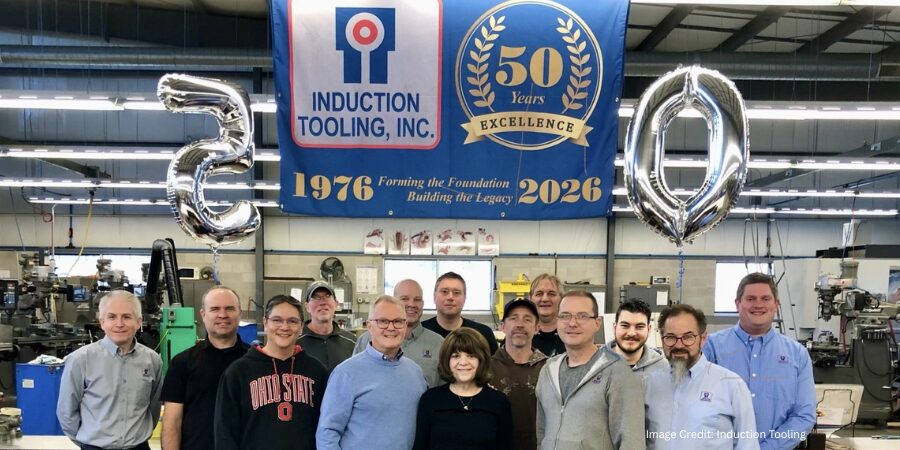
In 1976, what began as a small operation in a 400-square-foot garage grew into one of the most respected names in induction tooling. Today, Induction Tooling, Inc. (ITI), headquartered in North Royalton, Ohio, celebrates 50 years of designing and manufacturing specialized tooling that helps in-house and commercial heat treaters solve complex induction heating challenges across a range of industries, including automotive, aerospace, agriculture, medical, and mining.
Founded by William “Bill” Stuehr, the company was born from a simple observation. While working as a process design engineer at a heat treating company in the mid-1970s, Bill saw clients asking for induction heating that required specialized tooling.
Recognizing the opportunity, he set out on his own. By April 1976, he had delivered his first custom-designed tooling, marking the beginning of a business that would steadily expand over the decades.
Growth came quickly. The company expanded from his home garage to a few different facilities over the decades. In 2005, they finally settled into a 30,000-square-foot facility where they currently house their engineering, manufacturing, and laboratory testing capabilities.
Engineering Solutions for Induction Heat Treating
Induction hardening requires precision, and Induction Tooling has built its expertise around delivering that precision consistently. The company specializes in selective hardening quick-change inductors and related tooling, such as bus bars, adapters, and fixtures used in induction heat treating systems.
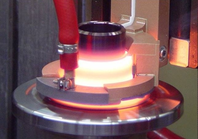
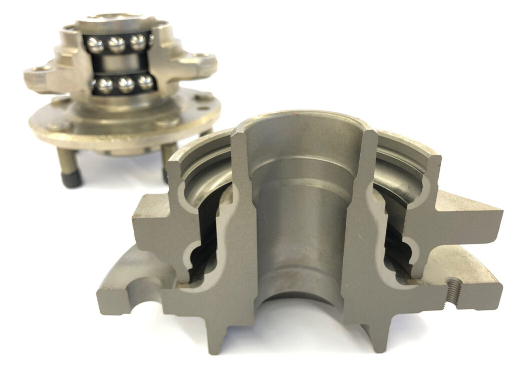
Wheel spindle heating in the laboratory | Image Credit: Induction ToolingWheel hub and spindle, etched pattern | Image Credit: Induction Tooling
By combining advanced design tools with decades of practical experience, the team develops custom solutions tailored to each client’s application. From hardening gears to heating complex shaft and hub components, the team’s engineers work closely with heat treaters to ensure performance, repeatability, and reliability in demanding manufacturing environments. Bringing that stewardship to records, all induction tooling designs have been meticulously maintained since the company’s inception; if ever that custom solution needed to be consulted, the team can and has immediate access to it.
Central to its capabilities is a comprehensive development process that moves from design, machining, and assembly to laboratory testing and metallurgical evaluation. This integrated approach allows the team to test and refine tooling and process parameters before implementation, helping improve quality and meet development timelines. The metallurgical lab also provides a key training experience, allowing designers, engineers, and production workers to see and test the result of their innovation and labor in real-time.
Wheel spindle being selectively hardened and quenched in Induction Tooling’s 3,000 sq ft testing and development laboratory.
A Culture Built on Teambuilding
While innovation plays a major role in their success, the company emphasizes the people behind the work more than anything. Skilled machinists and engineers with decades of experience collaborate across design, machining, and assembly to produce tooling that meets client specifications. This emphasis on teamwork and continual improvement is reflected in the company’s philosophy, which encourages learning, cooperation, and accountability throughout the organization.
The Next 50 Years
As Induction Tooling marks its 50th anniversary, the company continues to pursue the same mission that sparked its founding: inventing and engineering unique tooling solutions that improve induction heat treating processes. Recognizing the integration of automation happening within the industry, the team continues to research ways to further integrate robotics and automation into their processes, including experimenting with additive manufacturing.
For this company, the milestone is not just a look back at half a century of growth; it’s a reminder that innovation often begins with a simple idea and the determination to build something better.
Main image shows Induction Tooling, Inc. celebrating 50 years of innovation and design. If you have any comments or queries on this article, let us know at editor@heattreattoday.com.
Induction heat treaters know that proper coil design is crucial to increasing longevity, improving production quality, and cutting costs. Among the topics addressed in this paper about induction heat treat coil design and fabrication (presented by R. Goldstein, W. Stuehr, and M. Blackby at ASM International) are these:
The design and fabrication of induction heating coils over the years
The Variable of Flow and the Influence of Frequency
Control and Presentation
Structure, Quenching, and Cooling
The paper closes out with a case study using computer simulation to show typical temperature distributions in a single-shot induction hardening coil.
A good place to start whenever preparing parts for induction heat treating is the consideration of inductor design. The authors provide this list (an excerpt):
[spacer color="264C84" icon="Select a Icon"]
Considerations for Inductor Design
Induction heat treating coils are available in many shapes and sizes and must perform a variety of tasks in a given induction heat treating application. Depending on the application, the induction coil design requirements include:
Meet heat treatment specifications in desired production rates
Be robust enough to tolerate manufacturing variations
Mount into the induction machine
Have electrical parameters that match the induction power supply
Deliver quench
Have a satisfactory lifetime
Have satisfactory efficiency
Be repeatable from inductor to inductor
In developing a new induction heat treating coil and process, the first question is whether the component will be produced on an existing system or if a new machine must be built. In many cases, the part producer’s desire is to develop new tooling for an existing machine with spare capacity. This reduces the degree of freedom and can make the induction coil design procedure more complicated because a less-than-optimal frequency or coil style will be necessitated to fit the existing machine (Ref 16).
To determine the ability to use existing equipment, it is necessary to make an analysis of the part to be heat treated. Part material, prior processing, geometry, production rate, and heat treatment specifications all play roles. The part material and prior processing determine what the minimum heat treatment temperature should be, along with how much time is allowed for cooling. The part geometry and heat treatment specifications indicate how much energy is required, what the preferred frequency ranges are, and what type of induction method (i.e., single shot, scanning) is best suited for the application. Finally, the production rate determines how much power and/or how many spindles or stations are required.
Dr. Mihails Scepanskis is the CEO and co-founder of CENOS LLC.
Induction heating is an efficient way to quickly heat electrically conductive metals with pinpoint accuracy. It starts very simply, with a coil of conductive material, however initial design and optimization of the process are very complicated—it's hard to predict power, frequency, and heating time to get necessary results.
Computer simulation for induction heating is a powerful tool that enables engineers to investigate or design a physical system and process using a virtual mathematical model, thus saving time and money on numerous physical design iterations.
Dr. Vadims Geza is the chief scientist at CENOS.
Induction heating computer simulation offers the most efficient means of developing customized and optimized solutions and is, therefore, a necessity—not a luxury—in the modern induction heating industry. In this article, Dr. Mihails Scepanskis and Dr. Vadims Geza, both of CENOS LLC, based in Riga, Latvia, list features and benefits, obstacles and solutions of induction heating; advantages and disadvantages of computer simulation vs physical testing; what should be taken into account when choosing the right simulation software.
How simulation software can help companies save time and money on induction coil and process design
About Induction Heating
Today induction heating is used in many industrial processes, such as heat treatment in metallurgy, crystal growth and zone refining used in the semiconductor industry, and to melt metals which require very high temperatures.
Where Is Induction Heating Used?
Automotive
Construction
Aerospace
Metallurgical Plants
Oil & Gas Component Manufacturing
Special Applications
NASA's experimental NTP fuel elements heated with induction (Photo: CENOS)
Features:
Heat generation occurs inside the part.
Heating is contactless—as a result, product warpage, distortion and reject rates are minimized.
This method can provide very high power densities.
Heating may be highly selective in the depth and along the surface.
Any processing atmosphere (air, protective gas, vacuum) can be applied.
Very high temperatures may be reached.
The general benefits of induction surface heat treatment are
Short heating times—production rates can be maximized.
Optimized consistency—induction heating eliminates the inconsistencies and quality issues associated with open flame, torch heating, and other methods.
Extended fixture life—induction heating delivers heat to very small areas of your part without heating any surrounding parts. This extends the life of the fixturing and mechanical setup.
Environmentally sound without burning fossil fuels—induction is a clean, non-polluting process. Improves working conditions for employees by eliminating smoke, waste heat, noxious emissions, and loud noise.
Effective energy consumption—this uniquely energy-efficient process converts up to 90% of the energy expended energy into useful heat; batch furnaces are generally only 45% energy-efficient. Requires no warm-up or cool-down cycle.
Flexible adaptation to the hardening tasks
Closed loop computerized process control and compatibility with overall process automation
Large gear heat treatment (Photo: CENOS)
Obstacles:
Initial design and optimization of the process is very complicated.
It is hard to predict power, frequency and heating time to get necessary results.
Unlike other heating methods, induction heating requires specific coil design for each workpiece, so it's not very economic unless you need to process multiple similar workpieces.
To design and calculate the induction heating process you can:
Do a rough analytical estimation, then proceed with countless design iterations in the lab.
Find a professional company that can do induction coil and process design for you, but keep in mind that you most likely will be charged for design hours spent in the lab.
Buy a sophisticated multi-physics simulation software and hire a trained simulation engineer/analyst or pay for engineer's training (usually takes 3 months).
Start using a simple, affordable, and induction heating-focused simulation software like CENOS Platform, which features online training and templates for a quick and easy start.
Induction Heating and Computer Simulation
What Is a Computer Simulation?
Nowadays, in various industries, manufacturers prefer using software simulations over physical testing. Computer simulation is a powerful tool that enables engineers and scientists to investigate or design a physical system and/or process using a virtual mathematical model, thus saving time and money on numerous physical design iterations.
The vast majority of modern computer simulation software packages utilize numerical methods (e.g. finite element method or “FEM”) to evaluate extremely complex physical systems—systems that are otherwise impossible to precisely analyze. By leveraging the power of modern computer hardware, simulation software can provide substantial improvements in the efficiency, reliability, and cost-effectiveness in design and development processes.
Computer Simulation in Induction Industry
First works on computer simulation of induction coils were made in the 1960s. Due to limited access to computers, their low memory, speed, and poor programming methods, the computer simulation did not receive significant industrial application until the 1980s.
Now computer simulation has become a practical tool for everyday use in the induction industry. It allows the user to design optimal systems, improve equipment performance, dramatically reduce development time and costs, and better understand the process dynamics, etc.
Though there are still difficulties in an accurate simulation of non-linear and different mutually coupled tasks, computer simulation is effectively used for the design of induction heating coils and problem solution.
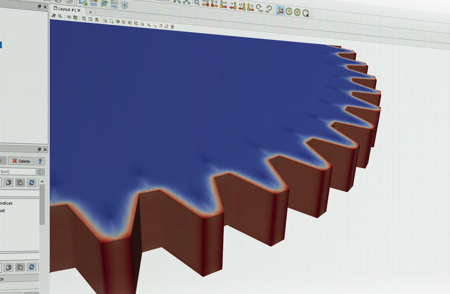
The 10 cm gear hardening with one concentric inductor at 170 kHz and 1.9 kA over 120 ms
Benefits and Value of Induction Heating Computer Simulation
The use of induction heating computer simulation software can promote substantial improvements in the performance and cost-effectiveness of induction heating equipment, in addition to large reductions in the cost and time required to design and develop induction heating processes.
From a design perspective, computer simulation is valuable for a number of reasons, two of the most notable being:
The physics involved in utilizing electromagnetic induction as a deliberate and controlled source of heat generation is extensive and multi-faceted. Computer simulation provides a quantitative approach to designing and developing induction heating processes, allowing complex physical phenomena that cannot be physically observed and/or measured to be clearly visualized and quantified.
Because electromagnetic induction offers an extremely effective, economical, and versatile means of heating conductive materials, the scope of induction heating applications is very broad. This includes (but is not limited to):
Furthermore, each of these general applications includes countless different workpiece types, geometries, materials, and heating requirements. As a result, no “universal solution” exists in the design of induction heating equipment. Induction heating computer simulation offers the most efficient means of developing customized and optimized solutions and is, therefore, a necessity—not a luxury—in the modern induction heating industry.
Combining Simulation With Real World Tests for the Best Results
Example of simulation results (Photo: CENOS)
Inductor design is one of the most important aspects of the overall induction heating system. A well-designed inductor provides the proper heating pattern for your part and maximizes the efficiency of the power supply, while still allowing easy insertion and removal of the part. With the right design, it's possible to heat conductive materials of any size and form, or only the portion of material required.
Computer Simulation vs Experimental Method
Computer Simulation
Advantages
Can work for any geometry and operating conditions
Demonstrates the entire dynamics of the process
Leaves records for future
Limitless accuracy of calculations
Does not require special equipment
Less expensive and less time-consuming
Future improvements expected
Provides 3D process visualization for customers (pictures, video)
Limits and Disadvantages
Requires special software and databases
Not all the processes may be simulated (as of today)
Does not provide physical samples
Experimental Method
Advantages
May provide the most reliable results
Can show the performance of the whole system including unexpected effects and troubles
Does not require a material property database
Provides physical samples for properties validation
Limits and Disadvantages
May require expensive equipment
Does not provide a good understanding of the process
Difficult to transfer knowledge (to scale a company)
Case dependent accuracy
Limited access to production equipment (expensive)
Time-consuming—may cause production delay due to multiple design iterations.
Challenges in coil design
The induction coil, also known as an "inductor", is essential to induction heating. Single-turn, flexible, multi-turn cylindrical, left-turn, right-turn, rod-shaped, hair-pin, parallel, ear-shaped, tiny, big—whatever the coil shape and size—the right design maximizes the lifetime of the coil and ensures lowest energy consumption and best effects on work process and materials.
Many factors contribute to a coil’s effectiveness: the care taken to make it, the quality of the materials used, its shape, its maintenance, its correct matching with the power source, etc.
Here are just three of the many hurdles to be overcome in order to make safe and efficient coils:
Impedance matching
It is necessary to achieve the correct impedance matching between the coil and the power source in order to use the latter’s full power. The coil designer must also consider that coils need five to ten times as much reactive as active power.
Magnetic flux concentrators
Concentrators focus the current in the coil area facing the workpiece. Without concentrators, much of the magnetic flux may propagate around the coil. This flux could engulf adjacent conductive components. But when concentrated, the flux is restricted to precise areas of the workpiece.
Water flow and speed
It is generally important to achieve an adequate flow of cooling water through the coil. When high power density is expected in the inductor, the coil designer must consider the flow rate and the water’s velocity. This is because velocity significantly influences the heat transfer between inductor and coolant and therefore has a major impact on the longevity of the coil. A booster pump is sometimes needed to maintain the desired flow and velocity. Professional designers will also specify a purity level for the water in order to minimize coil corrosion.
Tools and Processes Necessary To Ensure Coil Longevity and Performance
Advanced induction coil design includes:
Detailed analysis of specifications, available equipment, and environment
Coil style and heating process selection (scanning, single-shot, static, etc.)
3D design programs and computer simulation for coil head optimization
Analysis of benefits of magnetic flux controllers application
Advanced manufacturing techniques, mandrels to achieve tight tolerances
Testing in a laboratory or industrial plant for performance and final dimensional check
Final corrections if required
Designing and making induction coils is technically challenging. Computer simulation helps tackle some of the challenges, limiting costs and maximizing effectiveness.
CENOS Platform's mission is to help companies switch from old and cumbersome experimental methods to a powerful computer simulation that is simple, affordable, and induction heating-focused. CENOS, combined with real-world trials, will yield the best results in a fast and cost-effective way.
How To Choose the Right Simulation Software
The induction heating market is small compared to other industrial sectors, and there are only a few specialized simulation packages on the market that can be used for induction process and coil design. Induction heating simulation involves a set of mutually coupled non-linear phenomena. Many induction applications are unique and may require different program modules. In addition to computer simulation software, an extensive material database is necessary for accurate results.
1D, 2D or 3D?
Majority of practical simulations now are being made in 1D or 2D approaches. But with 1D and 2D, the structure and geometry of real induction systems are often very simplified. In reality, a majority of induction systems are 3D. In addition, interference of induction device and source of power must be considered in many cases. That's why 3D will ensure less space for errors and a more thorough analysis.
Cloud vs Desktop
Working with cloud-based software requires uploading your data to the third party. Frequently induction heating equipment manufacturers are not allowed to share their customer CAD files with a third party due to NDA. Furthermore, while cloud computing may provide increased calculation speed, one should consider the time it takes for uploading the design files and downloading the result files.
Importance of training & support (time, costs)
There is a common opinion that simulation software requires a specially educated (and well paid) simulation engineer/analyst, usually hired only for one kind of task—simulation. This is definitely true for sophisticated multi-physics simulation packages, which might require 3 to 4 months of intense training because of a plethora of numerical aspects which should be taken into account in order to get reliable results in a simulation. However, CENOS 3D desktop software keeps focus solely on induction heating and tries to avoid any unnecessary functionality which might confuse an inexperienced user. By using CENOS-dedicated templates, a beginner can run his first induction simulation in just under 30 minutes and become a pro user with any 3D geometry after 2 weeks of training, guided by CENOS engineers.
Cost
Licensing software can cost $20,000 to $80,000 up front plus additional annual payments in 20% value of purchase price just for support and updates. And that's only for an induction heating module, whereas CENOS's annual license is $7,200 and requires no upfront investment. Alternatively, one could consider a “pay as you go” purchase model, paid by hours, but one must keep in mind that 3D calculations take time, which might make this particular subscription model cost inefficient.
Open Source software—a free alternative with some drawbacks
Open source is very cost efficient—open source tools like Elmer or GetDP are free to use. However, these tools might require a long training period (6 to 10 months); plus extra steps and routines required for everyday simulation will take up to 1,000 additional hours a year. Overall, open source tools are a solid choice because they are validated by the community but not focused on user experience.
Benefits:
Community. Open source solutions often have thriving communities around them, bound by a common drive to support and improve a solution and introduce new concepts and capabilities faster, better, and more effectively than internal teams working on proprietary solutions.
The power of the crowd. The collective power of a community of talented individuals working in concert delivers not only more ideas but quicker development and troubleshooting when issues arise.
Transparency. Open source code means just that—you get full visibility into the code base, as well as all discussions about how the community develops features and addresses bugs.
Reliability. Because there are more eyes on it, the reliability of open source code tends to be superior as well. Code is developed on online forums and guided by experts. The output tends to be extremely robust, tried, and tested. In fact, open source code now powers about 90% of the internet and is being rapidly adopted across major enterprises for this reason.
Better security. As with reliability, open source software's code is often more secure because it is much more thoroughly reviewed and vetted by the community.
Drawbacks:
Because there is no requirement to create a commercial product that will sell and generate money, open source software can tend to evolve more in line with developers’ wishes than the needs of the end user. For the same reason, they can be less “user-friendly” and not as easy to use because less attention is paid to developing the user interface.
There may also be less support available for when things go wrong – open source software tends to rely on its community of users to respond to and fix problems.
Because of the way it has been developed, open source software can require more technical know-how than commercial proprietary systems, so you may need to put twice as much time and effort into training employees to the level required to use it.
Many different open source solutions are not compatible with each other. Take for example GetDP - an open source finite element solver, its core algorithm library uses its native pre-processing and post-processing tool Gmsh, which frankly, compared to other solutions, is not the best in its class.
CENOS Makes Open Source User-Friendly and Easy To Use
CENOS Platform uses GetDP solver and offers integration with far more superior open source tools like SALOME for pre-processing and Paraview for post-processing, which by default are not compatible with GetDP.
“CENOS” stands for “Connecting ENgineering Open Source”, highlighting its new software approach: connecting the best of open source tools in one seamless user experience. CENOS platform technology enables affordable simulation available for small to midsize companies by connecting third-party open source algorithms GetDP, Salome, and Paraview, developed by strong academic communities involving world top research centers and universities like Sandia National Lab, Imperial College, KU Leuven, and others. The academic world has already built plenty of smart algorithms; there is no need to charge money for the scientific heritage. Use of free open source algorithms makes it possible for CENOS to be affordable for everyone.
The company has built a user-friendly interaction layer and interconnection between previously incompatible separate open source software algorithms. CENOS Platform consists of a user interface, special data optimization procedures including necessary data reformatting for inter-operational compliance ensuring data flow and control between different open source tools. This way CENOS lets engineers save up to 80% of design time by replacing physical prototyping with powerful simulation software which is affordable and easy to use.
About the Authors: Dr. Mihails Scepanskis is the CEO and co-founder of CENOS LLC, based in Riga, Latvia. Dr. Vadims Geza is the chief scientist at CENOS.
Induction Hardening Tips: Equipment Selection for Scan Hardening, Part 3
This is the third installment of a multi-part column on equipment selection for induction heat treatment. Part 1, Dr. Valery Rudnev On . . . Induction Hardening Tips: Equipment Selection for Scan Hardening, covered types of scanners, scan hardening system setup, quenching challenges, maximizing process flexibility, and computer modeling. In Part 2, Dr. Valery Rudnev discussed another critical aspect of induction scan hardening: inductor design subtleties and a comparison of different fabrication techniques (brazing vs. CNC
machining vs. 3D printing).
In this installation, Dr. Rudnev focuses on Moveable Inductor versus Moveable Part.
Moveable Inductor versus Moveable Part
As stated in one of the previous installments of this column, when a scan processing mode is chosen, either the inductor or the part or both may be moved during the heating and quenching. This installment discusses the applicability of those approaches (movable inductor vs. movable part), as well as pros and cons associated with both techniques.
Figure 1. An example of scan hardening of track shoes for earth-moving machines that often specify deep hardness case depths (up to the 24 mm).
The choice to move the inductor or to move the part is primarily based on required production rate as well as on the size, weight, and geometry of the component compared to the size, weight, and geometry of the inductor: in other words, it depends on which of the two is easier to move.
Weight is an important factor because the movement can occur several hundred times each day and, in some cases of high production, even several thousand times per day. For example, during induction surface hardening of track shoes for earth-moving machines that often specify deep hardness case depths (up to 24 mm), it is much easier to move the inductor around the workpiece instead of moving the track shoes, the weight of which can exceed several thousand pounds. (Figure 1)
When moving the inductor, both flexible cables and hoses are used or the inductor is hard-bused to the transformer and the transformer or heat station moves with the inductor. In some cases, the power supply itself may be moved at a moderate rate to scan a stationary workpiece [1]. Another example of moving the inductor is surface hardening of trailer axles. (Figure 2)
Figure 2. (Left image) Horizontal scanner to induction harden both ends of a trailer axle. A walking beam system was incorporated into the machine for part transfer. At the heating station, the axle is lifted off the beam and the power supply and inductor are indexed to position for scan hardening. After the completion of surface hardening of one end, the axle is then lifted off the transfer mechanism and rotated 180° to induction harden the opposite end. Heavy-duty precision shafting and bearings are used for stability and consistency. (Right image) shows a close-up of a movable inductor to scan harden trailer axle ends. Heating time is less than 8 s per axle end.
The length of the part to be heated is also an important consideration When a component is of moderate weight, it is obviously preferable to move the part rather than the inductor. For example, it is much easier and more cost-effective to design a hardening system that anticipates moving a workpiece that weighs less than 0.25 kg (<0.5 lb) rather than moving an entire power supply, as it is shown in Figure 3.
Figure 3. Horizontal scanner that provides a maximum scan rate up to 200 mm/s (8 in./s). (Courtesy of Inductoheat Inc., an Inductotherm Group company.)
In other cases, it may not be practical to move very large and elongated components. It would consume too much floor space to move the part through a stationary inductor. In the case of low production rates, the best choice might be to move the inductor, but the length of the high-frequency power leads could become a problem with respect to voltage drop and power loss. In this case, it is preferable to move the inductor with the power supply attached. Then, the moving cables are operating at a low frequency (50–60 Hz) with lower voltage drop and power loss. In the case of high production, continuous horizontal systems may be more suitable.
The consideration of the length of the leads (e.g., cables or buses) from the power source to the inductor is important. They should be as short as possible to conserve energy and to allow the power source to operate properly without reaching any limits (for example, voltage limit). If these leads are too long, the inductance increase can be so significant that it may result in a substantial power loss and voltage drop. The voltage drop in the leads may even exceed the voltage at inductor’s terminals. Long leads could net an excessive total needed power, a measurable reduction in energy efficiency, and potential concerns regarding the process repeatability owing to the possibility of an appreciable inductance change of the flexible leads during their motion, that in some cases may negatively impact process repeatability.
Whether moving the inductor or moving the part, the induction system can be designed to be efficient and robust in order to ensure smooth and consistent operation and the production of quality parts.
I recommend Reference #1 to readers interested in further reading on this subject.
References
V. Rudnev, D. Loveless, R. Cook, Handbook of Induction Heating, 2nd Edition, CRC Press, 2017.
Dr. Valery Rudnev, FASM, IFHTSE Fellow, is the Director of Science & Technology, Inductoheat Inc., and a co-author of Handbook of Induction Heating (2nd ed.), along with Don Loveless and Raymond L. Cook. The Handbook of Induction Heating, 2nd ed., is published by CRC Press. For more information click here.
During the day-to-day operation of heat treat departments, many habits are formed and procedures followed that sometimes are done simply because that’s the way they’ve always been done. One of the great benefits of having a community of heat treaters is to challenge those habits and look at new ways of doing things. Heat TreatToday‘s 101 Heat TreatTips, tips and tricks that come from some of the industry’s foremost experts, were initially published in the FNA 2018 Special Print Edition, as a way to make the benefits of that community available to as many people as possible. This special edition is available in a digital format here.
In today’s Technical Tuesday, we continue an intermittent series of posts drawn from the 101 tips. The category for this post is Induction Heating, and today’s tips–#29, #73, and #83–are from Dr. Valery Rudnev, FASM, Fellow of IFHTSE, “Professor Induction”, Director of Science & Technology at Inductoheat Inc., an Inductotherm Group company. Dr. Rudnev is a regular contributor to Heat TreatToday.
Heat TreatTip #29
Induction Heating Non-Ferrous Metals & Alloys
Dr. Valery Rudnev, FASM, Fellow IFHTSE, Professor Induction, Director Science & Technology, Inductoheat Inc., an Inductotherm Group company
Steel components by far represent the majority of hot worked and heat-treated parts for which electromagnetic induction is used as a source of heat generation. At the same time, many other non-ferrous metals and alloys are also inductively heated for a number of commercial applications. Induction heating of low electrically resistive metals such as Al, Mg, Cu, and others typically require using lower electrical frequencies compared to carbon steels, cast irons, or high resistive non-magnetic metals (such as Ti or W, for example) and metallic alloys. The lower value of electrical resistivity results in smaller current penetration depth (depth of heat source generation), making it possible to apply much lower frequencies without facing the danger of eddy current cancellation.
Heat TreatTip #73
Induction Hardening Powder Metal
When induction hardening powder metallurgy (P/M) materials, it is good practice to have a minimum density of at least 7.0 g/cm3 (0.25 lb/in.3). This will help obtain consistent induction hardening results. When hardening surfaces that have cuts, shoulders, teeth, holes, splines, slots, sharp corners, and other geometrical discontinuities and stress risers, it is preferable to have a minimum density of 7.2 g/cm3 (0.26 lb/in.3). Low-density P/M parts are prone to cracking due to a penetration of the gases into the subsurface areas of the part through the interconnected pores. Interconnected pores contribute to decreased part strength and rigidity compared with wrought materials. In addition, the poor thermal conductivity of porous P/M parts encourages the development of localized hot spots and excessive thermal gradients and also requires the use of quenchants with intensified cooling rates to obtain the required hardness and case depths. This is so because an increase in pore fraction and a reduction in density negatively affect the hardenability of P/M materials compared to their wrought equivalents.
Heat TreatTip #83
Induction Hardening Cast Iron
Induction hardening of cast irons has many similarities with hardening of steels; at the same time, there are specific features that should be addressed. Unlike steels, different types of cast irons may have similar chemical composition but substantially different response to induction hardening. In steels, the carbon content is fixed by chemistry and, upon austenitization, cannot exceed this fixed value. In contrast, in cast irons, there is a “reserve” of carbon in the primary (eutectic) graphite particles. The presence of those graphite particles and the ability of carbon to diffuse into the matrix at temperatures of austenite phase can potentially cause the process variability, because it may produce a localized deviation in an amount of carbon dissolved in the austenitic matrix. This could affect the obtained hardness level and pattern upon quenching. Thus, among other factors, the success in induction hardening of cast irons and its repeatability is greatly affected by a potential variation of matrix carbon content in terms of prior microstructure. If, for some reason, cast iron does not respond to induction hardening in an expected way, then one of the first steps in determining the root cause for such behavior is to make sure that the cast iron has not only the proper chemical composition but matrix as well.
If you have any questions, feel free to contact the expert who submitted the Tip or contact Heat TreatToday directly. If you have a heat treat tip that you’d like to share, please send to the editor, and we’ll put it in the queue for our next Heat TreatTipsissue.
Induction Hardening Tips: Equipment Selection for Scan Hardening, Part 2
This is the second installment of a multi-part column on equipment selection for induction heat treatment. Part 1, Dr. Valery Rudnev On . . . Induction Hardening Tips: Equipment Selection for Scan Hardening, covered types of scanners, scan hardening system setup, quenching challenges, maximizing process flexibility, and computer modeling. In this installment, Dr. Valery Rudnev discusses another critical aspect of induction scan hardening: inductor design subtleties and a comparison of different fabrication techniques (brazing vs. CNC
machining vs. 3D printing).
Introduction
Hardening inductors are often considered the weakest link in an induction hardening system because they may carry significant electrical power and operate in harsh environments exposed to high temperatures, water, and other coolants while being subjected to mechanical movement and potential sudden part contact.
Single-turn or multiturn inductors may be used in scan hardening (Figure 1). Copper profiling and the number of turns is determined by the workpiece geometry, required hardness pattern, and the ability to properly load match the coil to the power supply without reaching the operational limits or by other specific process requirements, such as the production rate or the hardness pattern runout/pattern cutoff. [1]
Figure 1: Single-turn or multiturn inductors may be used in scan hardening.
The longer (in case of horizontal arrangement) or the higher (vertical arrangement) the scan coil is, the faster the scan rate can be. This is due to the simple fact that the longer inductor leads to a longer period when the part will be inside the coil; therefore, the scan rate can be greater. However, limitations on the maximum length of the inductor’s heating face may be associated with the maximum permissible runout.
Hardness Pattern Runout Control
Single-turn inductors with narrow heating faces (3mm-6mm wide) are used where a sharp pattern runout is needed. An example of this would be the case where a pattern must end near a snap ring groove. Inductors with wider heating faces or two-turn coils can be used when a faster scan rate is desired and an extended runout is permitted. The main disadvantage to the excessively wide heating face is that it may result in an unspecified shift of coil current density when hardening complex geometric parts due to an electromagnetic proximity effect. [1]
Inductor Fabrication Techniques
In applications where high process repeatability is critical (including automotive, aerospace, defense and other industries), the great majority of scan hardening inductors are CNC machined from a solid copper block, thus making them rigid, durable, and repeatable. CAD/CAM/CNC software programs are created that provide appropriate cutter-to-copper spatial relationships, which produce inductors of the required shape and precision regardless of complexity. Figure 2 shows a variety of finished and semi-finished CNC-machined hardening inductors. [2]
Figure 2: finished and semi-finished CNC-machined hardening inductors
In other cases, copper tubing (square, rectangular, round, or die-formed shaped tubes) may be used for coil fabrication (Figure 3). Copper tubing is typically annealed to improve its ductility, bending properties, and workability. When sharp bends or complex coil shapes are required, inductor segments made from tubing are assembled by brazing. Joints are often overlapped, creating tongue-and-groove joints. Butt-joints should not be used.
Figure 3: Copper tubing (square, rectangular, round, or die-formed shaped tubes) may be used for coil fabrication.
A complex geometry inductor that contains numerous brazed joints, and elbow-type 90° joints in particular, could experience impeded water flow in the cooling coil turns, shortening coil life. Poor quality brazed joints are prime candidates for water leaks affecting not only the coil life expectancy but also a quality of hardened components due to a potential soft spotting in the areas of water leaks. Eliminating braze joints or dramatically reducing their number, particularly in current-carrying areas, is the key to fabricating durable, reliable, and long-last inductors.
Additive manufacturing (AM), or 3D printing, delivers successful fabrication of fixtures, tooling, holders, etc. Recently, some inductors have been fabricated using 3D printing as well. It is important to keep in mind that AM is not a single technology but it comprises a number of processes including direct metal laser sintering, electron beam melting, directed energy deposition, direct and indirect binder jetting, and others.
Depending upon a particular AM technique used in fabricating hardening inductors, it may face major challenges to match properties of pure copper. This includes (1) obtaining sufficiently high thermal conductivity (2) or low electrical resistivity, (3) ensuring high volumetric density, and (4) having minimum amount of residuals, just to name a few. All these factors affect coil life. Therefore, if you compare 3D printed inductors with brazed coils comprising numerous brazed joints, in the majority of cases, the life of 3D printed coils will surpass life of brazed inductors because of elimination of brazed joints in current-carrying regions. In addition, fabrication accuracy and repeatability of AM inductors typically surpasses the accuracy of brazed or bended coils.
The situation is different when comparing life of 3D printed coils vs. CNC machined inductors. Fabrication accuracy of both processes is very similar, however, in high-power density applications even small degradation of above discussed four factors associated with AM might become essential causing greater probability of stress-fatigue and stress-corrosion copper failure of 3D printed coils compared to CNC machined inductors fabricated from pure copper. Another factor to consider is repairability of 3D printed inductors. If you need to do a revision then it would be most likely required you to re-manufacture 3D printed coils. Regardless of a fabrication method and for quality assurance purposes, it is beneficial to apply computerized 3D metrology laser scanner technology (Figure 4) to verify coil dimensional accuracy and alignment precision after inductor fabrication and assembly.
Figure 4: It may be beneficial to apply computerized 3D metrology laser scanner technology to verify accuracy and alignment after inductor fabrication and assembly.
Material Selection
Copper and copper alloys are almost exclusively used to fabricate induction coils due to their reasonable cost, availability, and a unique combination of electrical, thermal, and mechanical properties. Proper selection of copper grade and its purity is crucial to minimize the deleterious effects of factors that contribute to premature coil failure including stress-corrosion and stress-fatigue cracking, galvanic corrosion, copper erosion, pitting, overheating, and work hardening. Cooling water pH also affects copper susceptibility to cracking.
Oxygen-free high-conductivity (OFHC) copper should be specified for most hardening inductors. In addition to superior electrical and thermal properties, OFHC copper dramatically reduces the risk of hydrogen embrittlement and developing localized “hot” and “cold” spots. The higher ductility of OFHC copper is also important because coil turns are subjected to flexing due to electromagnetic forces. The higher cost of OFHC copper is offset by improved life expectancy of hardening inductor.
For scan inductors that are intended to heat fillets, an appropriate copper heating face region must be focused into the fillet area. Coil copper profiling and the use of flux concentrators (flux intensifiers) are beneficial to focus the magnetic field into the fillet. These applications require careful design because the induced current has a tendency to take the shortest path and stay in the shaft area rather than flowing into the fillet [1]. Therefore, all efforts must be made to focus the heat generation into the fillet. Typically, higher frequencies work better for this purpose.
Copper Wall Thickness
It is important to maintain sufficient wall thickness to carry the electrical currents. The wall thickness of an inductor’s heating face should increase as frequency decreases. This fact is directly related to both the current penetration depth in the copper δCu. [1] It is highly desirable for the current-carrying copper wall thickness to be 1.6 times greater than the δCu calculated at maximum working temperature. Increased kilowatt losses in the copper, which are associated with reduced coil electrical efficiency and greater water-cooling requirements, will occur if the wall is thinner than 1.6∙δCu.
The table below shows the variation of δCu vs. frequency at room temperature (20°C/68°F).
In some cases, the copper wall thickness can be noticeably thicker than the recommended value of 1.6∙δCu. This is because it may be mechanically impractical to use a tubing wall thickness of, for example, 0.25 mm (0.01 in.).
I recommend Reference #1 to readers interested in further discussion on design of hardening inductors.
Dr. Valery Rudnev, FASM, is the Director of Science & Technology, Inductoheat Inc., and a co-author of Handbook of Induction Heating (2nd ed.), along with Don Loveless and Raymond L. Cook. The Handbook of Induction Heating, 2nd ed., is published by CRC Press. For more information click here.
Induction Hardening Tips: Equipment Selection for Scan Hardening
Introduction
Induction scan hardening is one of the more popular techniques for strengthening various steels, cast irons, and powder metallurgy components. This scanning method is be used to harden flat surfaces or irregular shapes (e.g., rails, bumpers, bed-ways, support beams, track shoes for earth moving machines, teeth of large gears, etc.); however, it is most frequently used for hardening outside and/or inside surfaces of cylindrically shaped components, such as shafts, pins, raceways, etc. In scan hardening, the inductor or workpiece or both moves linearly relative to each other during the hardening cycle.
Depending on the workflow of parts, the induction system can be built as vertical, horizontal, or even at an angle, though vertical scan hardening is by far the most popular design. As an example, Figure 1 shows three variations of the InductoScan® family of modular vertical scan hardening systems.
Figure 1. Variations of the InductoScan® family of vertical modular scan hardening systems. (Courtesy of Inductoheat, Inc.)
What to Choose: Vertical Scanners vs. Horizontal Scanners
Both vertical and horizontal induction scanning systems are viable means to heat treat components. The decision of whether to use a vertical or horizontal scan hardening system is usually based upon the shape and length of heat treated parts, as well as the available space and a workflow throughout the plant or factory in which the equipment is to be installed. Horizontal hardening is often chosen when long workpieces are to be processed (typically 4ft/1.2m or longer) or when high production rates are needed for processing shorter parts.
Vertical scanners are typically associated with a smaller footprint. In the majority of applications, the cylinder-shaped workpiece (e.g., shafts) is positioned between centers or some other tooling or fixture. The workpiece may rotate inside the inductor to even out the hardening pattern around the circumference, or it may be located preferentially with respect to the inductor and processed without rotation when hardening workpieces of certain shapes. The quench spray typically impinges the part approximately 12mm (½”) to 40mm (1.5”) from the coil heating face and is angled away to prevent the quench from splashing back into the inductor. This dimension can vary with different types of steel, the scan rates, and the design specifics.
Setting Up Scan Hardening Systems
Vertical systems can be set up to process as many as four shafts at a time depending on the size of the shafts being processed and the available power source. Parts are loaded either manually or automatically onto a lower center. A loading assist “vee” block or nest may be used to steady the part as it is being loaded and processed. For larger parts, pneumatic cylinders lift the upper centers to facilitate loading. With vertical scan hardening, it may take an appreciable amount of time to process the workpiece because it must be loaded, scanned along the length up to the position where the heating process commences, fast scanned back down to the load-unload position, and then unloaded.
In contrast, a horizontal system is typically set up as a single continuous scanning line that allows parts to be loaded from a magazine and continuously fed to the exit of the machine. Depending on the specific heating requirements for the end of the component, parts are fed end-to-end through the heating coil and pass on to the next process. The loading system can push parts through the inductor by a pinch drive mechanism, conveyor, mechanical pushers, or other means, such as skewed rollers [1]. On a horizontal system, due to heavy duty roller support underneath, gravity, and any required stabilizing devices on top of the workpiece, the part is maintained in the center of the induction coil and quench ring. There is usually less risk of distortion than that which occurs with a vertical system where the part’s shape can change or warp if the part is not always centered.
However, during the heating process on a horizontal system, it may be more difficult to maintain the exact location of features of the part since it is commonly free rolling on the skewed rollers. For this reason, consideration should be given to a part’s shape, the symmetry of its positioning in respect to the heating coil, and selection of support devices. When horizontal systems are used for heat treating long parts of appreciable weight, it might be challenging to speed up or slow down the progress of the workpiece along the skewed rollers as quickly as might be done in vertical scanners with a servo-driven carriage that captures the part.
The roller system of horizontal scan hardeners can interfere with achieving symmetrical cooling of the workpiece since the location of the rollers and the rotation detection mechanism on shorter parts may be too close to the coil or quench barrel. Additionally, a stabilizing fixture may be required to prevent lighter and smaller workpieces from being moved axially by electromagnetic forces rather than the roller system. As with the vertical system, some type of rotation detection must be employed to ensure that the part is actually rotating as it is passing through the heating coil.
Quenching Challenges
Quenching presents a challenge with horizontal scanning [1]. When scanning vertically, quenching takes place below the inductor, which naturally allows gravity to pull the quench fluid down, therefore, the quench fluid continues to flow on the part long after it has passed the quench chamber, which is beneficial to achieving circumferential uniformity of quenching as well as reaching temperatures suitable for handling. When quenching horizontally, the effect of gravity is different and the way the quenchant falls from the workpiece varies leading to the probability of non-uniform cooling along the circumference of the heat-treated component (e.g., quenchant may run along the top of the part but fall off the bottom).
It is also more critical for horizontal scanners to maintain a sufficient distance between the inductor exit and the quenching device due to the higher probability of the liquid quenchant splashing back into the inductor. This could lead to irregular results caused by different cooling rates affecting the hardness consistency as well as the magnitude and distribution of residual stresses.
All of these factors can be summarized as follows:
The main process differences between vertical or horizontal scan hardening systems lie in the part handling and quenching subtleties.
With some scanners, splash shields, deflectors, and drip trays may be needed to prevent the backsplash of the quench fluids.
Maximizing Process Flexibility of Induction Scanners
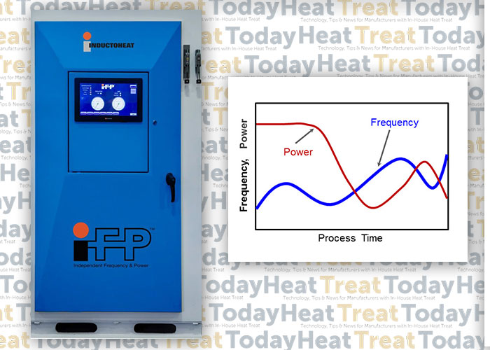
It is commonly assumed that all scan hardening systems exhibit high process flexibility with respect to the workpiece length and, to some extent, variations in the diameter of the part. Conventional scan hardening provides the ability to vary the speed and power during the process, which controls the amount of heat applied to different areas of the part. Recently developed Statipower-IFP® inverter technology (Figure 2) extends the capability of conventional induction hardening systems to instantly and independently adjust not only power and scan rate but also frequency (5kHz to 60kHz range) during scan hardening cycle [2].
Figure 2. Statipower-IFP® inverter allows instant and independent adjustment of frequency (5kHz to 60kHz) and power during scan hardening cycle. (Courtesy of Inductoheat Inc.).
In the past, the flexibility of induction scanners was limited to using power supplies with single operational frequency. However, when processing a family of parts or components with numerous geometrical irregularities (including large diameter changes, multiple holes, sharp shoulders, combinations of solid and hollow areas, various required case depths, etc., see Figure 3), the fixed frequency in conventional induction scanners can be inadequate, producing “hot” and “cold” spots, as well as unwanted microstructures (e.g., local grain boundary liquation and grain coarsening).
Figure 3. A family of components exhibiting numerous geometrical irregularities
Single frequency scanners have been used to tweak the process in an attempt to promote or suppress thermal conduction [1,2], resulting in a compromise in achieving the desired metallurgical quality, production rate, and process capability. In the heating stage, compromise affects the ability to provide heat-appropriate austenization, but it also presents challenges in the quenching stage.
Austenization is followed by a quenching stage (spray or immersion). If the available, fixed frequency of a conventionally designed induction scanner is considerably higher than optimal then the depth of heat it generates (current penetration depth) is smaller than needed, which might not be sufficient in establishing necessary austenization. In this case, to reach sufficient austenization, the scan rate and applied power must be reduced to allow thermal conduction to the required subsurface depth. Unfortunately, a noticeable heat surplus might still occur.
An Example of Compromised Results
As an example, Figure 4 shows the computer modeling results of the induction scan hardening of a hollow medium carbon steel shaft that has diameter changes, a chamfer, and a groove. Nominal outside diameter is 0.05m (2”); nominal inside diameter is 0.02m (3/4”). Because the shaft is symmetrical, only the top half was modeled. Temperature variations at four selected areas of the shaft are monitored at different inductor positions. Frequency was constant at 15 kHz.
The scan rate and coil power were varied during hardening as an attempt to accommodate changes in the shape of the shaft.
Reducing scan speed (in some cases substantially) not only adds unnecessary cycle time, but if the scan speed is too slow, certain regions of a heat-treated component may cool below the critical temperature before it enters the quench zone, resulting in an undesirable formation of mixed structures and upper transformation products, as well as reduced or spotty hardness readings.
If the fixed frequency of a conventionally designed scanner is noticeably lower than optimal, it may produce a deeper than required austenized layer, affecting hardness depth, transition zone and creating excessive distortion. In this case, increasing scan rate and power density should minimize, but not eliminate, this outcome. Such a compromise can still affect local spray quenching producing undesirable metallurgical results.
Conclusion
It is important to remember that applied frequency has the greatest impact on depth of induction heat generation. A new generation of Statipower-IFP® inverters (Figure 2) eliminates these drawbacks by optimizing the metallurgical quality of induction scan hardening, expanding process flexibility and maximizing a production rate. This patented technology can be effectively used in both vertical and horizontal induction scanners. Reports [2] show changing both coil power and frequency during scan hardening can reduce peak temperatures on 70oC (125oF) while maintaining the required hardness pattern.
I recommend Reference #1 to readers interested in further discussion on induction scan hardening subtleties.
Doyon, V.Rudnev, C.Russell, J.Maher, Revolution-not evaluation-necessary to advance induction heat treating, Advance Materials & Processes, September 2017, p.72-80.
______________________________________________
Dr. Valery Rudnev, FASM, is the Director of Science & Technology, Inductoheat Inc., and a co-author of Handbook of Induction Heating (2nd ed.), along with Don Loveless and Raymond L. Cook. The Handbook of Induction Heating, 2nd ed., is published by CRC Press. For more information click here.
One of the great privileges of being the publisher of an industry publication is meeting many outstanding people. Some are exceptionally wealthy, some not. Some have a deeper degree of “outstandingness” in that they are kind and others-centered; others not so much. Due to the kindness of Ginny Smith, daughter of Hank Rowan, both of Inductotherm fame, I had the great honor of meeting Hank Rowan, the founder and former CEO of the Inductotherm Group of Companies. This short article is mostly about Mr. Rowan, although it is also about the people Mr. Rowan, I’m sure, would have championed.
My brief encounters with Mr. Rowan were two and both very brief. I’ll tell you more about my experiences with Mr. Rowan and his daughter, Mrs. Smith, below, but for now, you should take some time to listen to the excellent podcast that Malcolm Gladwell did about Hank Rowan shortly after Mr. Rowan’s passing in 2015. Fascinating.
Click here to be taken to the podcast that Mr. Gladwell did about Hank Rowan.
Mr. Rowan
Encounter #1. Not long into my publishing career with BNP Media (I was the publisher of Industrial Heating magazine from 1994-2014), I heard about Mr. Rowan’s book The Fire Within. Wanting to get a little better acquainted with the induction industry, I searched for the book. This was pre-Amazon days…or at least before I knew how to use it! Being a rather forward person, and not having any luck finding the book elsewhere, I called Inductotherm in Rancocas, NJ, to see if I could obtain a copy of the book from them. They answered the phone.
Receptionist: “Hello, Inductotherm, how can I help you?
Me: “Hi, my name is Doug Glenn and I was wondering if I could get a copy of Hank Rowan’s book from you?”
Receptionist: “Hold please.”
Next Voice: “Hello. This is Hank Rowan, how can I help you?”
Me: (Stone-dead silent…….) “Mr. Rowan! Nice to meet you….”
I went on to explain why I was calling and we had a nice discussion. Needless to say, I was surprised and appropriately impressed that Mr. Rowan took calls of this nature. He was a genuinely nice person. I got two copies of the book several days later with a short, hand-written note from Mr. Rowan.
Encounter #2. Multiple years later when I was making a sales call on Ginny Smith, Mr. Rowan’s daughter, who I mentioned earlier, I was about ready to leave and Mrs. Smith asked me if I’d like to meet her father. I was a bit surprised but, of course, said “yes.” We commenced to walk up the steps and directly into Mr. Rowan’s office. He had just completed some sort of minor surgery on his face and was slightly bandaged up…but still at work…and if I remember correctly still coming into work nearly every day even at the advanced age of 80+. His reception was warm and the three of us had a brief and pleasant conversation. No pretension; just a normal guy…as was his daughter, Ginny. I, of course, recounted the book request incident to him (not knowing what else to talk about) and he didn’t act surprised.
Some exceptionally wealthy people are aloof. Not Mr. Rowan.
Other Industry Champions
I’m going to step out and speculate a bit here because I did not know Mr. Rowan well enough to say what I’m about to say emphatically…I could be wrong, but I think Mr. Rowan would probably champion the not-so-rich-and-famous people in the heat treat industry. People like Dan Reardon of Paulo Products with whom I’ve had the privilege of developing an online relationship (!). Dan and I have corresponded by LinkedIn only. I’ve never met him in person. Nonetheless, I consider Dan to be an industry (and life) champion. I think Mr. Rowan would as well.
If you’ve listened to the Malcolm Gladwell podcast (see above), you know that Mr. Rowan donated millions of dollars to educate the every-day engineers in and around his New Jersey home. It would be hard to say how many educational lives Mr. Rowan has impacted.
Mr. Reardon, on the other hand, father of five, is, as I am, struggling to get our kids (Dan has 5, I have 4) through college. Based on the LinkedIn exchanges Dan and I have had, it is easy to conclude that Dan is not independently wealthy. By his own admission, it is a “struggle” to know how he and his wife are going to do it — how are they going to put all the kids through college and still have a half decent retirement. My guess is that if Dan had to choose, he’d sacrifice his retirement for the benefit of his kids. Go Dan!
These are the types of people that make the heat treat industry tick. There are undoubtedly thousands of others that could be mentioned. Malcolm Gladwell doesn’t have time to profile them all; nor do I, but please know that each and every one of you that sacrifices himself for the good of others is a champion.