Curious about proper gas atmospheres needed to meet high-tolerance standards for additive manufactured parts before, during, and after the heat treating process?
Learn about them in this detailed original content article from Heat TreatToday’sAerospace 2021 print magazine. The author, Lisa Mercando, Ph.D., is the marketing manager of strategic marketing & development at Air Products. You can access the other articles in our digital edition here. Enjoy the Technical Tuesday!
Lisa Mercando, Ph.D. Marketing Manager, Strategic Marketing & Development Air Products
In a world of rapid prototyping and production of metal components, it is imperative to have the proper gas atmosphere to produce quality parts. Argon, nitrogen, and helium are commonly used to create inert atmospheres in order to meet the high-tolerance standards required for additive manufactured (AM) aerospace parts. Industrial gases are used every step of the way from powder production to various additive manufacturing techniques to finishing processes that include heat treating and hot isostatic pressing (HIPing).
Inert gas atomization is the best method to obtain dense, spherical particles, which are best for AM applications where the desired particle size is usually less than 100 microns. Additionally, inert gas atomization greatly reduces risk for oxidation, providing a high level of powder purity and quality. Helium provides the best results when its superior heat transfer capabilities are needed. This process achieves the following properties: dense and spherical particles; high quality and purity metal powders; and narrow particle size distribution. We can provide high pressure gases for powder atomization and hydrogen-based atmospheres for powder reduction and annealing.
Image demonstrating metal additive manufacturing
To meet the high-tolerance standards required in additive manufacturing–particularly for aerospace–nitrogen and argon are commonly used to provide inert atmospheres. The use of helium, with its high thermal conductivity, offers an interesting option for minimizing the thermal distortion of elongated parts during printing. An inert atmosphere provides numerous benefits on a printed part by:
reducing oxidation of printed parts by lowering the oxygen concentration in the build chamber
improving safety through the inerting of combustible dust during powder handling and sieving
creating a stable printing environment by maintaining constant pressure in the print chamber
mitigating powder clumping in the feed tube
preventing part deformation by controlling thermal stress through effective cooling
Gas requirements differ based on the process being used and the material being printed.
Often, AM aerospace parts require additional processing to achieve the desired final properties. This is done mainly in the form of heat treating, sintering, or HIPing. All three processes have industrial gas requirements for preventing oxidation. Heat treating with argon, nitrogen, hydrogen, or a nitrogen/hydrogen blend can relieve internal stresses and enhance part properties such as strength, ductility, and hardness. In sintering applications, nitrogen/hydrogen blends or argon/hydrogen blends are important in producing near-net shape parts with increased strength and uniformity. High pressure argon is used in HIPing applications to provide fully dense parts with increased strength and reliability.
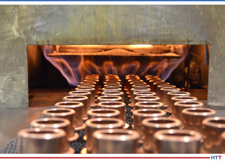
Image of a furnace heating metal parts
In addition to providing the bulk industrial gases required, the company has developed state-of-the-art process intelligence systems. These systems monitor atmosphere composition parameters to ensure the process is running with the desired gas atmospheres and provide alerts for any needed maintenance or adjustments. Decades of metals processing experience in gas supply, applications, process knowledge, and safety are applied to help improve heat treating efficiency and part quality.
Remote tank monitoring is one example of the company’s Process Intelligence™. Operators increasingly rely on data to closely track critical process parameters, such as the use and inventory of vital industrial gases. This tank monitoring system enables operators to remotely check their supply levels and monitor usage from a touch screen in the plant, on their laptop, or on their mobile device. Customized daily reports are a common way to stay current on their industrial gas supply.
For heat treatment operations using a furnace atmosphere that is flammable or potentially flammable, an inert purge gas – typically nitrogen – is utilized to help ensure safe operation. This system alerts operators to the condition of the liquid nitrogen supply and helps them remotely track their supply and usage of gases. Optional system alarms allow operators to safely initiate a controlled purge shutdown, enabling compliance with NFPA 86 by confirming they have adequate liquid storage levels, or ensuring their nitrogen piping temperature remains at a safe level. Typically installed near the furnace operation, the remote touch screen on the base station displays conditions of all bulk gas storage tanks and can use both audible and visual alarms to warn the operator of a potentially critical situation.
Tank Monitoring
In addition to using inert gases, such as nitrogen and argon for the 3D printing processes, GE Additive Manufacturing, located in Cincinnati, OH and a major manufacturing center for additive manufacturing, also performs post processing heat treatment/sintering on the metal parts to enhance part quality. Their capabilities allow for the production of quick, precise parts with high levels of accuracy, even on intricate shapes and geometries across multiple applications.
Conclusion
If you are prototyping and producing metal components, be sure to consider the importance of achieving the optimum gas atmosphere to efficiently make quality parts. The heat treat postprocessing of AM metal parts is often required to produce the high-quality parts specified for the aerospace industry.
About the Author: Dr. Lisa Mercando is the marketing manager, Strategic Marketing & Development, for Air Products’ metals processing industry. She has worked at Air Products for 28 years in a variety of roles and responsibilities and is the author of several patents and technical articles.
Excess air plays multiple roles in heat treating systems. Learn about its importance in combustion and heat transfer, and why being well-informed will help your system run at peak performance.
This original content article, written by John Clarke, technical director at Helios Electric Corporation, appeared in Heat TreatToday’s Aerospace March 2021 print magazine. See this issue and others here.
John B. Clarke Technical Director Helios Electric Corporation Source: Helios Electric Corporation
Is your system running optimally? The following discussion will provide a better, albeit abbreviated, understanding of the role of air in combustion and heat transfer.
Excess air in heating systems plays many roles: it provides adequate oxygen to prevent the formation of CO or soot, can reduce formation of NOx, increases the mass flow in convective furnaces to improve temperature uniformity, and at times, wastes energy. Excess air is neither good nor bad, but it is frequently necessary.
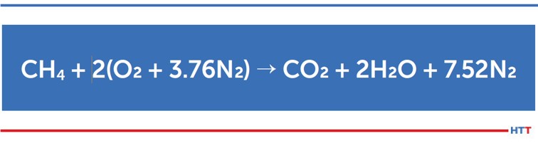
To begin, we must first look at a basic formula. For our discussions, we will replace natural gas, which is a mix of hydrocarbons with methane (CH4). The oxygen (O2) is supplied by air.
The above simplified formula describes perfect or stoichiometric combustion. The inputs are methane and air (where only the O2 is used to oxidize the carbon and hydrogen in the methane), and the products of combustion (POC) consist of heated carbon dioxide (CO2), water vapor (H2O) and of course nitrogen (N2). (The actual reaction is far more complex and there are other elements present in air that we are ignoring for simplicity.) As we can see from the equation, the oxygen we need to burn the methane comes with a significant quantity of nitrogen.
In practice, it is very difficult to even approach this stoichiometric or perfect reaction because it would require perfect mixing, meaning that each molecule of methane is next to an oxygen molecule at just the right time. Without some excess air, we would expect some carbon monoxide and/or soot to be formed. Excess air is generally defined as the percent of total air supplied that is more than what is required for stoichiometric or perfect combustion. For natural gas, a good rule of thumb is to have about 10 cubic feet of air for every one cubic foot of fuel gas for perfect combustion. Higher air/fuel ratios, say 11:1, are another way of describing excess air.
In most heating applications, the creation of carbon monoxide and other unburnt hydrocarbons should be avoided, except in the rare cases where they serve to protect the material being processed. Employees must be protected from CO exposure; and soot can damage not only equipment, but the material being processed.
Source: Heat Treat Today
The amount of excess air that is required to find and combine with the methane is dependent not only on the burner, but also on the application and operating temperature as well. Some burners and systems can run with very little excess air (under 5%) and not form soot or CO. Others may require 15% or more to burn cleanly. Just because a burner performs well at 10% excess air in application A, does not necessarily mean the same level is adequate in application B.
Once the quantity of air exceeds what is needed to fully oxidize or burn the methane, combustion efficiency will fall because the added air contributes no useful O2 to the combustion process, and it must be heated. It is very much like someone putting a rock in your backpack before you set out for a 16-mile trek. Taking this analogy further, higher process temperatures equate to climbing a hill or mountain with that same rock — the higher the climb, or the higher the process temperature, the more energy you waste. Sometimes this added weight or mass can be useful.
The higher the excess air, the greater the mass flow. In other words, the total weight of the products of combustion goes up, and the temperature of the CO2, H2O, N2, and O2 goes down. If we are trying to transfer the heat convectively, this added mass or weight will provide improved heat transfer and temperature uniformity. A simple way to think of temperature uniformity is that the lower the temperature drop between the products of combustion and the material being heated, the better the temperature uniformity. Many heating systems are specifically designed to take advantage of this condition – higher levels of air at lower temperatures. This is especially true when convective heat transfer is the dominant means of moving heat from the POC to the material being heated (when the process temperature is roughly 1000°F or lower).
Source: Heat Treat Today
Some heating systems are specifically designed to operate as close to perfect combustion as is possible as the material is heated then switch to higher levels of excess air to increase the temperature uniformity as the setpoint temperature is approached. In other words, it provides efficient combustion when temperature uniformity is less of an issue and a very uniform environment as the material being processed nears its final setpoint temperature.
Of course, a system can be supplied with too much air, which can waste energy, but also prevent the system from ever reaching its setpoint temperature. The energy is insufficient to heat all the air, the material being processed, and compensate for furnace or oven loses. In these instances, it is obvious that we must reduce the air supplied to the system.
In indirect heating systems – where the products of combustion do not come in contact with the material being processed, like radiant tubes, for example — air in excess of what is required for clean combustion provides limited benefit and should generally be avoided. In these systems, it is best to play a game of limbo, “How Low Can You Go,” so to speak. Test each burner to see how much excess air is required to burn clean and add a little bit for safety. Remember, if you source your combustion air from outside in an area with significant seasonal variations, the blower efficiency will change, and seasonal combustion tuning is required.
Lastly, some burners require a minimum level of excess air to operate properly. This additional air prevents critical parts of the burner from overheating – or the air may limit the formation of oxides of nitrogen (NOx). In this application, altering the burner air/fuel ratio could generate excessive pollutants or even destroy the burner.
Efficiency is important, but the process is king. There is no magical air-to-fuel ratio and no single optimum level of excess air in the products of combustion. Each application is unique and must be thoughtfully analyzed before we can confidently say we have optimized our level of excess air. But careful attention paid to the effect that excess air has on your fuel-fired systems will pay dividends in improved safety and efficiency.
About the Author:
John Clarke, technical director at Helios Electric Corporation, a combustion consultancy, will be sharing his expertise as he navigates us through all things energy as it relates to heat treating equipment.
Greg Stapcup CEO/President SITES Medical Source: SITES Medical website
SITES Medical has ordered two vacuum furnaces, expanding their heat treat capabilities. SITES Medical is an orthopedic technology development company that invents and de-risks new technologies, and the furnaces will aid them as they collaborate with OEMs to bring technologies to market and drive mutual growth.
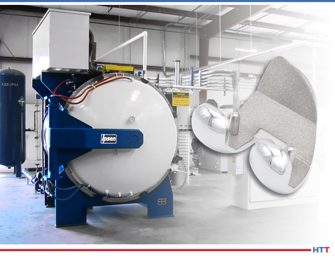
The new furnaces from Ipsen will accommodate increased volume resulting from growth in business. Each has a work zone size of 24” wide x 24” high x 36” deep with an all-metal hot zone. The furnaces will be used for orthopedic implant processing such as stress relieving Ti and CoCr components, as well as diffusion bonding of Ti and CoCr implants.
"After reviewing the options available for thermal processing solutions," said Greg Stalcup, president/CEO of SITES Medical, "we elected to purchase the Ipsen TurboTreater® vacuum furnaces due to their high quality and reliability."
ThisHeat TreatNews piece runs more like a case study, and we want you to see the tasks associated with bringing a heat treat process in house. In this case study, a global manufacturer and supplier of solutions in industrial process instrumentation,KROHNE Group, was outsourcing their large parts to a commercial heat treater in France.
The study details decisions involved in creating a furnace in cooperation with a furnace supplier with locations in Virginia and in the UK as well as shares how a certain particular fixture performed over time and the associated upkeep.
KROHNE Group is a global manufacturer and supplier of solutions in industrial process instrumentation. Within the UK, KROHNE is the group’s global center of excellence for Coriolis mass flowmeter technology. Its manufacturing plant in Wellingborough is where the OPTIMASS range of mass flowmeters is produced.
Their process of manufacturing products often involves working with specialist materials such as Duplex 31803 and Super Duplex 32750 stainless steels. Particularly with regards to materials such as Super Duplex, it is highly critical that the brazing process is completed correctly.
However, KROHNE’s largest products to be brazed are up to two meters in length and no suitable furnace exists within the UK that has the hot zone capability to process such a large product. This meant that the brazing of this product was subcontracted to a supplier in France, which brought challenges with lead times, transport, and associated cost issues.
The objective: bringing the brazing process in-house
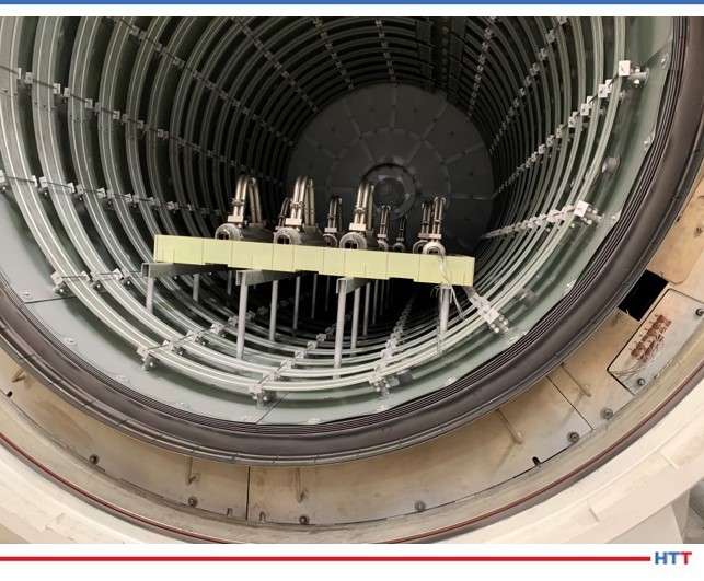
Furnace Loaded Source: Erodex UK
KROHNE’s management team made the decision to bring the process of brazing their larger products in-house, thus ensuring complete control over quality and lead times.
Following a significant investment in the UK’s largest horizontal vacuum furnace, the company required assistance with the design and manufacture of a fixture that would possess the specific hot zone capability, be of appropriate size and at the same time cope with weight, cost and distortion limitations whilst processing the larger products.
Evolution of fixture design
Discussions with Erodex started around six to nine months prior to when the furnace was due to arrive. The original concept design provided by the Erodex UK team was based around using graphite plates and spacers.
Following close consultation with their KROHNE counterparts, this was reviewed and it was determined that a flat grid method would be more suitable, due to strength requirements of the fixture and to enable the required reduction in fixture weight.
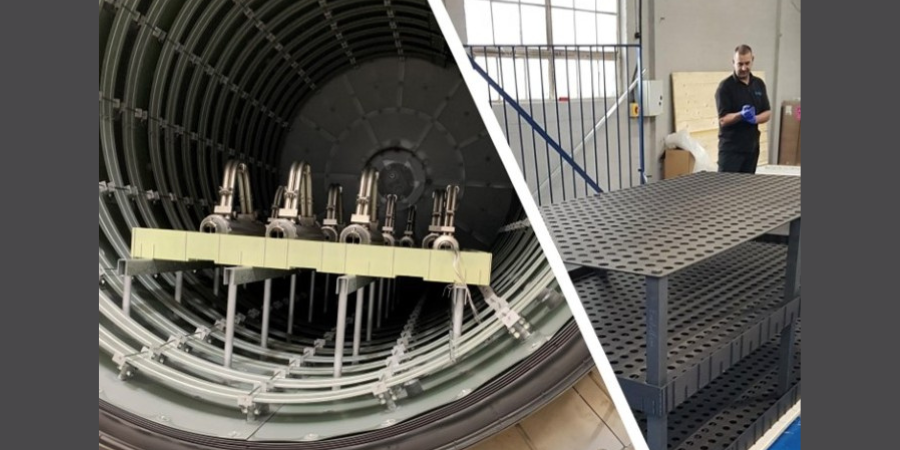
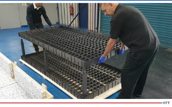
The resulting design was a 2.4m x 1.2m carbon fibre composite (CFC) fixture consisting of 2 layers and a cover plate to ensure that there was no direct radiation heat onto the components processed on the top layer and that heat is evenly distributed within the furnace. Darren Hawes, production engineering manager at the company comments: “We then had a further meeting and added in channels and a cover plate that sits on top of the CFC grid structure to maintain 0.1mm flatness.
“Perforated holes were added to allow the 360-degree gas cooling to flow underneath the fixture to the parts, because cooling is one of the critical features of the process. Side rails were added to the fixture to remove the possibility of any parts falling off and we added lifting points to the fixture, so once removed from the furnace, if the loader were to break down at any point, the fixture could be removed from the loader by overhead cranes”.
Why was Carbon Fiber Composite (CFC) graphite the material of choice for fixture manufacture?
Durability properties such as their high strength, stiffness, high thermal shock resistance and high fracture toughness, combined with being lightweight and having low rates of thermal expansion, CFC is the optimum material solution for charging systems in vacuum furnaces.
Tom Harrison, manufacturing engineer at KROHNE explains why they opted to manufacture the fixture from CFC graphite: “We had to find the right material for the fixture when considering weight, cost and distortion limitations and we could not find another material that was comparable to CFC for achieving this.
“The CFC fixture is lightweight yet as the temperature increases within the furnace the material gets stronger. Our main requirement of the fixture and the plate itself was to have a 0.1mm flatness tolerance, so when we manufacture and process our parts, any distortion of the fixture does not impact on the assembly that is being processed.
“The straight tube assemblies being processed within the furnace also have a 1/600mm straightness tolerance. Up to two metres we can have 3mm distortion end to end in the bow of the tube. To get that right, we required the fixture base to be as true as possible, so that we are not adding any additional distortion into the processing of the parts. The CFC fixture was therefore designed and manufactured by Erodex to deliver on that 0.1mm flatness constraint.
“In addition, the more mass within the furnace, the greater the effect on heating and cooling rates. A metallic fixture can act as a heat sink, using CFC reduces the mass greatly so our process is optimised and the energy we do use is used efficiently.”
Additional benefits of using a CFC grid structure.
An added benefit of a CFC grid structure is that if individual parts of the fixture break, only these need to be replaced. This contrasts with a metallic grid, where the whole grid would need to be replaced or refurbished, resulting in a significant reduction in maintenance costs.
Furthermore, Duplex stainless steel and Super Duplex stainless steel are mainly used for corrosion resistance, meaning that any carbon or other contamination picked up from the fixture itself could affect the metallurgy of the material, which in turn can add further complications to the products being processed.
To avoid this, the CFC graphite fixture was coated in a Yttria Zirconia coating to prevent any carbon ingress into the material. Hawes continues: “As we moved through the process, the design became more complex, so having their expertise at hand to help develop this was very beneficial to us.”
Fixture 3 Source: Erodex UK
Fixture assembly and operation.
Erodex assembled the fixture prior to coating and provided a video demonstrating how this should be repeated. Following coating of the fixture, the team were back on site to reinforce this with demonstrations of the ease of assembly to all KROHNE end users.
Hawes’ team needed to make sure the fixture was precisely central within the furnace every time it is loaded, so the supplier also provided a specialized forklift which utilizes two guides that sit underneath it to centralise the load as it goes in the furnace.
Harrison adds: “The fixture itself has been used now since October, we have completed numerous cycles and it is holding up to design requirements of flatness, the coating is performing well and ultimately, the fixture is achieving what it was required to do… We vacuum clean the fixture and furnace after every cycle to remove any debris coming from the processing. The fixture also goes through a maintenance check/ two weekly burnout to remove any contaminants that may have come onto the fixture because of the processing of the products in the furnace.
“We have also used the CFC graphite fixture to process a product as part of our furnace validation that was previously processed by a subcontractor. We could see that there was 7mm distortion end to end on the part provided by the subcontractor. Once we processed it through on the fixture all the contact points were then level again. We would have not been able to achieve that in a subcontract furnace.
“Ultimately, this has given us full control over processing. It has given us the capability to develop our processes and increase productivity and allows continuous development and improvement of the process too.
“For example, we had identified a few issues with how one cycle was run, where we were positioning the monitoring thermocouples to ensure the parts are fully up to temperature before we started the brazing part of the process, so it has given us further knowledge on that, which in turn has benefitted the product being processed.”
Marcin Stokłosa Project Manager Nitrex Poland LinkedIn.com
An Ankara-based manufacturer has expanded their heat treat capabilities to design and manufacture subcomponents, as well as next-generation prototypes. With the five-technology system, the company will increase the product development and time to market of a variety of components for electromechanical systems and actuating mechanisms used in aviation, land, and sea vehicles.
The client coordinated with the Nitrex R&D department in Canada to obtain this new system. Additionally, an associated commercial heat treater based in Istanbul, Turkey supported the project with trial production of this nitriding system.
With the “Nitrex NX Connect app,” noted Marcin Stokłosa, project manager at the Poland location, “[the client] can remotely manage furnace operations and nitriding processes from anywhere.”
Engineered geometry increases strength, decreases stretch, and withstands thermal cycling.
For today’s Technical Tuesday, we are sharing an original content article on how innovative design of wire for mesh belts in heat treat can reduce costs to heat treaters. Technical writer Del Williams writes, that though it seems that manufacturers regard the “periodic replacement of wire belting simply a cost of doing business, innovative alternatives have been developed that can significantly prolong its life and drive down operational cost.” Read on to learn more!
Engineered geometry increases strength, decreases stretch, and withstands thermal cycling.
Whether for automotive, aerospace, or heavy equipment, manufacturers using heat treatment – which can reach temperatures up to 2400°F and vary from a few seconds to 60+ hours – need conveyor belting that can withstand the rigors of the process. However, traditional round balance weave wire belting has changed little in 100 years and often requires annual replacement, causing costly production downtime.
Heat treating is essential to improve the properties, performance and durability of metals such as steel, iron, aluminum alloys, copper, nickel, magnesium, and titanium. This can involve conveying to hardening, brazing, and soldering, as well as to sintering furnaces, carburizing furnaces, atmosphere tempering furnaces, and heat processing in annealing and quenching furnaces. Parts treated can range from bearings, gears, axles, fasteners, camshafts and crankshafts to saws, axes, and cutting tools.
Heat treat-grade balance weave belts – made of temperature-resistant stainless steel or other heat resistant alloys, suitable to be run on a conveyor with friction drive – can cost thousands of dollars, depending on the dimensions and quality. So, even though wear and premature replacement seems inevitable, such wire belting should not be considered a low-cost consumable. While many manufacturers using heat treating consider periodic replacement of wire belting simply a cost of doing business, innovative alternatives have been developed that can significantly prolong its life and drive down operational cost.
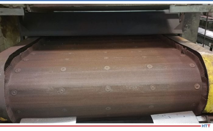
Conveyor belting for heat treating process Source: Del Williams
Although heat resistant wire belting is available, repeated thermal cycling between heating, soaking, and cooling while carrying substantial loads can continually weaken its structure until it fails. The greater and more frequent the temperature fluctuations in heat treatment steps, the shorter the wire belt’s usable life becomes.
In addition, on conveyor belts, belt stretch accelerated by heat and dynamic loading forces on the belt, is typically the main cause of breakage and failure.
Fortunately, industry innovation in the form of engineered, “shaped” wire belting has minimized these challenges. The design vastly prolongs usable life with increased strength and decreased stretch, which dramatically curtails replacement costs and production downtime.
This approach can also help to extend the longevity of wire belting used with increasingly popular powder metal parts, particularly sintered parts that may be heat treated to enhance strength, hardness, and other properties. In such cases, powder metal serves as a feed stock that can be processed into a net-shape without machining.
Resolving the Core Issues
Although conventional round wire belt has been the industry standard for generations, the geometry of the wire itself contributes to the problem.
Traditional round wire belt and even top-flattened wire belting is prone to belt stretch and premature replacement, particularly under high heat treatment temperatures. In testing, typical round and top flattened conveyor wire belt have been observed to stretch approximately 7%.
Even though many producers of conveyor wire belting simply import semi-finished product and finish it domestically, at least one U.S.-based manufacturer has gone to the root of the problem.
“Shaped” wire is designed to provide more strength in the wire belt of a given diameter so it can better withstand high heat processing conditions. This significantly prolongs its usable life.
As an example, one engineered wire belt, called Sidewinder, by Lancaster, PA based Lumsden Belting, compresses and expands wire so it is taller than it is wide with flat sides.
To begin with, the patented side flattened wire’s “I-beam” design provides 3 times greater structural support for heat treated parts compared to standard round wire. The added height of the wire also provides a longer wear life without needing heavier wire. Together, the design limits belt stretch to only 1-2%. This minimizes the potential for damaged belt. Minimal belt stretch also helps the conveyor belt to track straighter, improving production throughput with less required maintenance.
The design significantly extends the usable life of wire belt conveyors used in a variety of heat treat processes. This ranges from hardening, brazing, and soldering to sintering, carburizing, and atmosphere tempering furnaces.
It is also prolonging wire belt conveyor life in secondary powder metal processes used to improve hardness and other mechanical properties. In this vein, it could be utilized in a mesh belt sintering furnace, where compacted parts are placed in a controlled atmosphere and heated. It could also be used in processes such as quench and temper, case carburizing and induction hardening.
When heat treatment is used for hardening, followed by rapid cooling submerged in a medium like oil, brine or water, the shaped wire belt also enhances the open area for the same gauge wire. This reduces residue build up and eases cleaning, while minimizing drag.
Although the cost of the shaped wire belt is slightly more than traditional round wire, for manufacturers relying on heat treatment the gains in lifespan and production uptime can provide a speedy ROI.
About the Author: Del Williams is a technical writer based in Torrance, California. Images provided by the author.
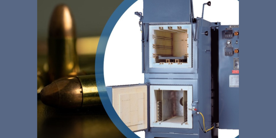
A leading Eastern European ammunition manufacturer expand their heat treat capabilities with a dual-chamber heat treating and temper furnace along with an oil quench tank. The equipment will play a supportive role in keeping key production equipment up-and-running with thermal processing of munitions projectiles.
The L&L Special Furnace Co., Inc. model QDS124 has two chambers: the top chamber rated to 2350°F is used for heat treating various steels and other non-ferrous materials. The bottom chamber, which is rated for 1250°F, includes a recirculation fan and baffle for tempering, stress relief, or pre-heating.
Shipped with the furnace was an accompanying QTO1224 oil quench tank. The quench tank has a working size of 12” high by 12” across by 24” deep and holds 65 gallons of oil. Included is a hinged safety lid, immersion-style heater with thermostat, and an agitator with explosion-proof motor for use with oil. The quench tank and furnace are NFPA86-compliant for safety.
A Midwest manufacturer expands their heat treat capabilities with a dual chamber furnace. With this furnace, the manufacturer will heat treat their small tool steel parts in-house in a timely manner.
The supplier, Lucifer Furnaces, identifies that the furnace, a Model RD8-KHE18, is a space saving dual chamber unit with working dimensions of 12”H x 14”W x 18”L in both upper and lower chambers. The upper hardening chamber is rated up to 2200°F while the lower convection oven tempers up to 1200°F.
This specific unit was customized with a programmable controller with an overtemp safety system for the upper chamber as well as a 7-day timer with alarm for audible event notification. Both chambers are lined with a multilayered 4.5″ combination of lightweight firebrick hotface insulation and mineral wool backup insulation for energy efficient operation. The firebrick is precision dry fit inside the chamber with staggered seams for reduced heat loss while allowing for thermal expansion.
Heat TreatRadio host Doug Glenn and Mark Hemsath, talk about hardening basics. What is it, why does it matter, and how do we do it? This is a great primer episode to kick off our three-part series with Mark. Listen and learn!
Mark was formerly the vice president of Super IQ and Nitriding at SECO/WARWICK, and is now the vice president of Sales - Americas for Nitrex Heat Treating Services.
Below, you can either listen to the podcast by clicking on the audio play button, or you can read an edited transcript.
The following transcript has been edited for your reading enjoyment.
Doug Glenn (DG): Mark, I want to welcome you to Heat TreatRadio. Welcome!
Mark Hemsath (MH): Thank you, Doug. It's nice to be with you today and thanks for having me on the show to talk about this interesting subject. I'm not quite sure if I'm an expert on it, but we will certainly try to talk about it.
DG: I'm sure you know more than most of us – that's why you're here! First of all, as I mentioned, you are the VP of Super IQ, IQ being integral quench, not necessarily intelligence quotient – although, you are a smart guy. You are the VP of Super IQ and nitriding for SECO/VACUUM. Both of those are processes and both of those are dealing with hardening. Tell us a little bit of your background and then we'll jump into the topic of hardness of metals.
MH: I'm not a metallurgist. I did take metallurgy at college and I've been living it most of my life, but I didn't train to be a metallurgist. Instead, I got involved in the furnace business, and being involved with furnaces you have to do something with those furnaces. Typically, those furnaces allow you to do different things, like soften and harden metals. My background is that for many years, I worked with my father helping to design furnaces for the industry and we developed different furnaces. Some furnaces were for annealing, some for tempering, some vacuum processes, you name it. I joined SECO/WARWICK a number of years ago and I spent quite a bit of my early days in ion nitriding and SECO/WARWICK was involved with gas nitriding. That was of extreme interest to me. I took a liking to that and decided to become a subject expert on nitriding. Now, I've been asked to also get involved with our carburizing product, which is breaking into the market – we call it Super IQ. That is obviously carburizing as a surface hardening process. Not to mention, we also do through hardening in those furnaces, and we can go into some of those details a little bit more here today.
DG: For people who might not know, when we talk about hardness, we're talking about the hardness of a metal. Most people would think, all metal is hard. I mean, that's one of the characteristics of metal, but if you wouldn't mind, give us the “hardness 101” class: What is it and why is it important when you talk about hardness for metals?
MH: I think the most important thing is that with metals, you're trying to get certain features that allow it not to wear over time. At the same time, you want the part to last. You don't want it to break, you don't want it to chip, you don't want it to seize up, so there are a lot of different things you can do with the parts to give them certain wear characteristics and hardness. There are other things – anti-friction, etc. – that you can do with surface finishes, such as with nitriding, which offer hardness to the part, but in a slightly different way than you might think, just on basic hardenbility. But, whatever we're talking about, we're trying to prevent parts from wearing, and that's typically why you try to harden the parts.
DG: How do we measure hardness, or what are the units that we typically measure?
MH: You have different scales out there, depending upon what you're trying to measure. If you're just trying to measure the surface, you might go with the file hardness or you might go with a test where you don't have such a heavy hardness on there. There are different Brinell hardnesses: You've got the HRC, the HRB, and different scales out there. You've got the Vickers hardness, and all different types of equipment designed to very accurately measure the hardness of a part and also to try to figure out how that hardness is changing throughout the material.
Typically, in most materials and in the processes that you're doing, because you have some thickness of material and a lot of it is related to both the quench rates etc., you're going to get hardness that varies throughout the part. So, they have come up with different ways of measuring that and there are a number of different scales out there. You can look that up and decide. Some people like to use one over the other, but typically, they are all designed to do the same thing: try to get an accurate reading of what the hardness is.
DG: I've heard the more common ones, I think you've mentioned them: Rockwell is a hardness measurement, Vickers is a hardness measurement, and Brinell is a hardness measurement. So, those are the scales that are used. We're not going to get into how those tests are done and things of that sort, but we certainly could at some point in time.
[blocktext align="right"]“I think the most important thing is that with metals, you're trying to get certain features that allow it not to wear over time. At the same time, you want the part to last.”[/blocktext]
MH: I'm not an expert on doing the tests. I've seen them done many times, but there are guys that are really good at that. Same with microstructures, right? Looking at that and understanding how things change within the steel and seeing it under different magnification, gives the scientists some really good knowledge about what's going on within the steel.
DG: Again, “hardness 101”: A person often hears, when dealing with metals and hardness, about surface hardness or through hardness. Can you tell us about those things? What's the difference? Why is that important?
MH: A part that you make, in a lot of instances, you want it to be as hard as possible for wear characteristics, but at the same time you don't want the part to fail because the core properties are too hard and can be brittle. Typically, what you have is people trying to impart certain types of features onto the surface and still retain the so-called core properties of that material. Obviously, you heat it up to austenitic temperatures and you quench it and you try to transform as much of that steel as possible to martensite, and then you try to temper it back.
A number of things that you're doing there are going to change the properties of the steel. That's why people will use different tempering temperatures to get different core properties. They'll use different surface treatments, whether carburizing (which will give you a higher surface hardness by driving more carbon into the surface) or induction hardening, in which you're heating up just the outer part of the steel and then quenching the outer part. Obviously, you can only go so deep because you're quenching it from the outside, but that will give you almost a double type of feature within the material. You're starting out with the core properties that you want – a certain hardness, a certain ductility, and a certain capability to function, let's say, a shaft – and then you want to give it some hardness. If you have the right steel, you can harden that just by taking it up to temperature with induction heating or with flame heating and then quickly quenching it to get the properties that you want on that outer.
DG: There are some properties in there that I want to make sure our listeners understand. You mentioned the idea of hardness and ductility. Those two things tend to be on opposite ends. I know there are much more technical descriptions of this, but the harder something is, the more brittle it tends to be, and when it's brittle, it takes less to crack it or break it. Whereas if it's ductile, it's softer, it can take more of an impact without breaking. For example, let's just use a gear: On the gear teeth, on the outer edge of the gear, you want that to be very hard so there's good wear, but you don't want it to crack so you keep the inside of that gear, (that's away from the surface side of the gear), soft. Yes?
MH: Yes. And there is a lot that goes into gear design. You don't want high impacts, obviously, you want the teeth to mesh together. There are people that induction harden gear teeth, there are people that carburize gear teeth and there are people that nitride gear teeth. They're all trying to do something on the teeth, and even though you're doing something on the teeth, you still have to also impart certain properties to the core part of the gear itself to make sure that nothing breaks or falls apart on the gear, the main core part of the gear itself.
(Source: Inductotherm)
DG: You did also mention the fact that there are some steels that are more easily hardenable than other steels. I've heard there are high hardenability steels and there are low hardenability steels. What's the difference?
MH: In general, iron is an element that is common to all steels. Now, there is tremendous science that has happened over the last decades on putting different alloying elements into the steels, whether it's chromium or titanium or vanadium or you can name all the different ones. Some of them are called micro alloy and some of them are more main alloys, but they all provide different types of properties to that alloy steel which then gives that steel certain characteristics. There are more steels created today than I could ever mention. You can buy huge books on that from ASM and get all of the different properties of the steels. Tool steels have quite a few alloying elements in them, and they have a very high hardenability. They're also more expensive, so people are not going to want to use expensive steels with all of those expensive alloying elements for basic automotive transmissions, or what have you; it just gets too expensive.
I should also say that carbon makes up a big part of that, too. The carbon in the steel is, obviously, why we call it carburizing because it will put hardness into it. But we also have what we call low carbon steels, medium carbon steels and high carbon steels. Then you start throwing in the alloying elements with that and you get all kinds of variations.
DG: So, typically, a high carbon steel is going to be much more easily hardened because it's got more carbon in it to start with and you don't necessarily have to add carbon into it during the heat treating process.
MH: Right. But when you heat and quench those parts, they also have different properties, as well.
DG: Is it only steels that can be hardened?
MH: I'm not an expert on it, but there are other types. There are some stainless steels – martensitic stainless steels – and there are different age hardening steels… which are still steels. There is aluminum, which has different properties depending upon what other elements they put in that; they can do some different types of hardening on those. Titanium by itself is a fairly hard metal, etc. Most of the people that we deal with, or whom we're talking about, are the people who are using steels to start with, a lot of times fairly inexpensive steels. But, we also, in vacuum furnaces, do very high-end steels, such as tool steels, like H13 air hardenable tool steels, etc.
DG: Let's jump back to steels. What are the typical heat treatment processes that enhance hardness, that increase the hardness?
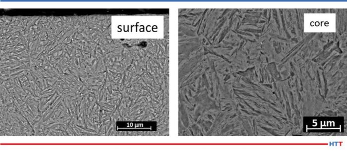
Microstructure of the carburized steel. Source: Surface Hardening Vs. Surface Embrittlement in Carburizing of Porous Steels - Scientific Figure on ResearchGate. Available from: https://www.researchgate.net/figure/Microstructure-of-the-carburized-steel_fig2_326653574 [accessed 3 Mar, 2021]MH: First of all, we have carburizing. As we spoke before, when you have a steel and you impart carbon into that steel, it tends to make it harder. What carburizing does, is it focuses that effort of putting carbon only into the surface. This means that you can have different core properties of that steel versus the outer properties. Then you can drive that carbon fairly deep into the surface, if you want. Now, deep means something like 2 mm, and above that are starting to get fairly deep cases. 2 millimeters is .079 inches. You do this by putting the part, at austenizing temperatures, into an atmosphere which is rich in carbon.DG: Let's stop here to define. Again, this is a non-technical definition of austenizing. To me, when I think of an austenizing temperature, that means even though that part is still “solid”, the fact of the matter is, that piece of metal is kind of in solution; things are moving around inside.MH: You've changed the structure. Then, when you quench it, you're trying to cool it very quickly so that you can get different structures out of that steel.We're talking here surface hardening or surface engineering. There are quite a few, actually. Some of the more common, obviously, are the ones we talked about here. There are basically four very common ones: carburizing, nitriding, carbonitriding, and nitrocarburizing. They are different. (Although, in Europe, sometimes they reverse those names a little bit between carbonitriding and nitrocarburizing.) I'll explain to you what, I believe, those are and why we call them that.
Carburizing is just as I was saying: driving carbon into the surface of the steel. It gets a very high hardness in the steel, depending upon what type of steel you have. It's typically done with lower carbon steels so that you can put the carbon into the surface. That's why we do it, because it's a lower carbon steel.
Nitriding is not an austenitic process; it is a lower temperature process. It's called a ferritic process. What that means is you don't go into the phase transformation where you have to go and quench the steel to get those properties. You're not going to get much in the way of dimensional shift or growth that you would get from the austenizing steel, and that's very beneficial. By driving nitrogen into the surface, you get a very high hardness. Now, you also need to have things in that surface of the steel other than just iron. You have different alloying elements which combine very easily with nitrogen, such as chromium, titanium, aluminum, vanadium, and some of those other things which will combine with the nitrogen, which either comes from an excited nitrogen atom via ion nitriding or comes from the disassociation of ammonia from gas nitriding where the nitrogen then transports itself into the steel surface and making those hard items.
[blocktext align="left"] “Nitriding is not an austenitic process; it is a lower temperature process. It's called a ferritic process. What that means is you don't go into the phase transformation where you have to go and quench the steel to get those properties.”[/blocktext]
In carbonitriding, it's identical to carburizing except you throw some ammonia in there. This is typically done at a lower temperature because ammonia breaks down very quickly at high temperature, so you're trying to stay right at the lower edge of that. You're throwing ammonia in there because the nitrogen will impart a very hard surface along with the carbon. It doesn't go in as deep but it's usually done as a 'down and dirty' very hard surface on a part, typically, a fairly inexpensive part.
Nitrocarburizing is like nitriding, but the focus is on the white layer, on the compound zone, which is a very hard layer of iron nitrides and iron nitrogen carbides. You get a very hard layer. They call it the compound zone because you have both a gamma prime zone, which is one element, and you have an epsilon zone, and those have very unique properties for the surface of the steel.
DG: Those are the main carburizing processes – carburizing, nitriding, carbonitriding, and nitrocarburizing. We'll dig deeper into those in our next episode, and also cover the processes, perhaps the types of equipment that those processes are done in, just for a little bit more education. Then, we’ll do a third episode where we'll talk about why we're hearing more recently about nitriding, low pressure carburizing, and single piece flow – and perhaps something that is near and dear to your heart, Mark, and that is some hybrid systems of a batch interval quench, which your company happens to call the Super IQ. Thanks for being here today.
Doug Glenn, Heat Treat Today publisher and Heat Treat Radio host.
To find other Heat Treat Radio episodes, go to www.heattreattoday.com/radio and look in the list of Heat Treat Radio episodes listed.
A North American heat treater is expanding their capabilities with a large pit gas nitriding furnace. The furnace will be designed by a North American based vacuum furnace manufacturer.
Piotr Zawistowski Managing Director SECO/VACUUM TECHNOLOGIES, USA
Source: secowarwick.com
The supplier, SECO/VACUUM Technologies (SVT), says their gas retort nitriding furnaces use uniform high convection heating, precision nitriding potential, and ammonia control along with vacuum purging to reduce operating costs and process a variety of metals. Processes possible with retort technology include gas nitriding, ferritic nitrocarburizing (FNC), post oxidation, tempering, age hardening, and stress relieving.
“I believe our team is one of the most adaptable and technically sound groups of experts in the thermal processing industry,” commented Piotr Zawistowski, managing director at SVT. He also notes that a consultative approach benefits both parties, especially in types of situations where an unfamiliar process is being adopted.