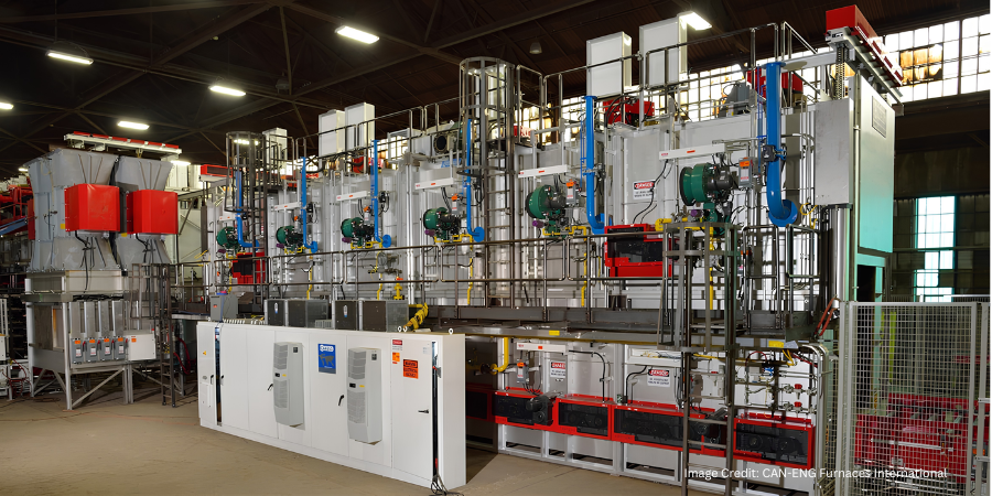
An advanced aluminum T6 heat treatment system has been selected to replace an existing line that no longer meets increasing production requirements and evolving quality expectations. The new system combines solution heat treatment, rapid water quenching, and artificial aging to improve thermal processing performance, metallurgical consistency, energy efficiency, and productivity for aluminum casting applications.
CAN-ENG Furnaces International, a furnace manufacturer based in Niagara Falls, Ontario, has been awarded a contract to design and manufacture the continuous roller hearth aluminum casting T6 heat treatment system. The system will incorporate continuous roller hearth solution heat treatment and artificial aging furnaces, along with the company’s rapid quench transfer system.
The integrated design is intended to provide precise thermal processing while minimizing transfer time to the water quench, helping to achieve consistent metallurgical performance and product quality. The client selected the new system to replace an existing heat treatment line that could no longer satisfy increasing production requirements and evolving quality expectations.
The replacement system is expected to provide improved furnace temperature uniformity, enhanced product handling and process reliability, automated rapid transfer water quenching for improved metallurgical consistency, reduced energy consumption, a lower risk of part damage and distortion, and increased equipment uptime and productivity compared with conventional conveyor-based systems.
The project expands CAN-ENG’s installed base of aluminum heat treatment systems in North America and international markets.
Press release is available in its original form here.
Like many industries, the heat treating industry is facing a significant labor shortage today — marked by tight hiring pools, high turnover, and growing demand for skilled workers. Unfortunately, the labor shortage isn’t ending any time soon.
In this climate, training solutions that are efficient, scalable, and accessible become crucial. The MTI Online Academy for Heat Treaters (run by the Metal Treating Institute, the largest network of commercial heat treaters worldwide) offers a robust solution tailored to these needs.
Top Benefits for Navigating Labor Challenges
Accelerated Onboarding & Skill Development
MTI’s new employee onboarding training course | Image Credit: MTI
MTI’s Academy offers eight certificate programs, from New Employee Onboarding to Qualified Furnace Operator, Technical Specialist, Quality Specialist, and Management Specialist, plus a safety and supervisory skills track. Companies can standardize onboarding processes and ramp up worker proficiency faster, reducing productivity lags typical in understaffed environments.
Enhanced Productivity, Revenue & Retention
Companies that invest in training see:
24% better profit margins
17% improved productivity
40% higher retention rates
Notably, 40% of new hires leave within the first year due to poor onboarding; robust training helps reverse that.
Compliance-Ready and Industry-Standard Training
Academy modules align with requirements for ARP 1962, Nadcap, CQI-9, and other certification benchmarks. This ensures personnel are trained to meet audit-ready standards, reducing compliance risk, which is particularly important when staffing is lean.
Flexible, Accessible, and Cost-Effective
MTI’s Heat Treat Management Specialist example of course offerings | Image Credit: MTI
Courses are available 24/7 worldwide, mobile-friendly, user-centric, and affordable for any budget. Employers gain flexibility to train employees across shifts and geographies without costly facility-based scheduling.
Modular, Structured Learning Paths
The Academy outlines credit hours for each certification (e.g., Furnace Operator: ~16 credit hours; Technical Specialist: ~25; Quality Specialist: ~63; Management Specialist: ~78). This transparent, tiered structure enables targeted training based on role demands and skill gaps, helping to optimize training time and resource allocation.
Support for Leadership Development
Beyond technical skills, the Academy offers leadership and supervisory programs, covering communication, team development, decision-making, DEI awareness, and more. Developing internal leaders helps build resilience, improves morale, and supports retention, especially when talent supply is thin.
Part of a Trusted Industry Network
MTI is a 501(c)(6) nonprofit established in 1933, offering the largest commercial heat treating network, breadth of resources, and credibility. Training through MTI not only builds skills but also connects learners to a broader professional community.
In a time when finding and retaining skilled heat treaters is tougher than ever, the MTI Online Academy for Heat Treaters provides a compelling solution: accessible, aligned with industry standards, modular, and designed to boost productivity, retention, compliance, and workforce development. By integrating MTI’s Academy into their workforce strategy, companies can effectively counter labor challenges while laying the foundation for sustained growth and operational excellence.
Additive manufacturing (AM) has transformed how metal parts are designed and produced, but it is also changing the role of thermal processing. As engineers develop alloys specifically for additive manufacturing — and tailor process parameters to achieve increasingly complex microstructures — heat treatment is evolving from a downstream finishing operation into a critical part of the overall materials design strategy.
This Technical Tuesday installment is a Q&A with Heat Treat Today Digital Editor Pat Reyes, in which Olga “Dr. O” Ivanova shares her perspective on what that shift means for manufacturers with in-house heat treating and commercial heat treaters.
With more than 15 years of experience in advanced materials and additive manufacturing, Olga “Dr. O” Ivanova is the founder of Dr.O Strategies, where she advises executives, startup leaders, and engineering teams on additive manufacturing technology integration and commercialization. A 2026 Additive Manufacturing Users Group (AMUG) DINO Award recipient, she brings expertise spanning materials chemistry, process design, and performance validation, helping organizations bridge the gap between scientific innovation and scalable production.
In the discussion that follows, Ivanova explains why additive-specific microstructures demand a different way of thinking about thermal processing, how emerging alloy systems may reshape traditional heat treatment practices, and why thermal processors have an opportunity to become collaborators in materials development rather than simply the final stop in the manufacturing chain.
From Process to Strategy
Pat Reyes: How do you see the relationship between material design, additive process parameters, and thermal processing evolving over the next decade?
Dr. O: I see this evolving from sequential handoffs to integrated co-design. Today, these disciplines operate in silos — alloy selection, then build parameters, then heat treatment, each handed off to the next.
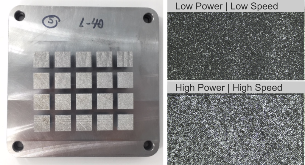
Different LPBF processing parameters produce distinctly different microstructures in the same tool steel, illustrating how build conditions shape the material entering heat treatment. | Image Credit: Dr.O Strategies
AM breaks that model. The thermal history during printing shapes the microstructure as much as the alloy chemistry does. Laser power, scan strategy, layer thickness, cooling rate — all of them determine what the heat treater receives.
Consider a nickel superalloy like Inconel 718. The powder morphology affects how it absorbs laser energy, which determines the as-built stress state, which governs whether a standard aging cycle actually hits its target. Change any one variable and you change the outcome.
Over the next decade, the winning question will shift from “How do we heat treat this alloy after printing?” to “How do we design the alloy, print parameters, and thermal strategy together?”
Heat treatment becomes a design variable, not a corrective step.
Pat Reyes: What do thermal processors most need to understand about additive-specific microstructures?
Dr. O: The most important concept: AM does not replicate conventional microstructures. It produces non-equilibrium structures that wrought and cast materials never experience.
Rapid melting and solidification cycles — repeated thousands of times per build — create metastable phases, columnar grains aligned with the build direction, and complex residual stress states. A thermal processor who treats an AM part as “just another batch” misses what makes it unique.
Related Reading: New to Inconel 718? Click on the image above to explore its history, aerospace applications, and production fundamentals as you dive deeper into how additive manufacturing is changing its thermal processing.
You might receive a familiar alloy like Ti-6A1-4V or Inconel 718, but the starting microstructure can be fundamentally different from what the standard heat treat schedule expects.
Residual stress relief isn’t just about preventing distortion. It’s about unlocking predictable properties. And HIP porosity closure must happen at the right stage relative to solution treatment and aging. These aren’t small differences, they’re the difference between reproducibility and scatter.
I’d point practitioners to standards like ASTM F3055-22 for qualification frameworks. But the principle holds: applying traditional schedules designed for wrought stock may solve the wrong problems or create new ones.
Rethinking Heat Treatment for AM
Pat Reyes: Are current heat treatment approaches generally sufficient for metal AM parts?
Dr. O: For established alloys in mature applications, yes, adapted conventional cycles generally suffice. If your goal is matching wrought performance in aerospace structures, current methods work.
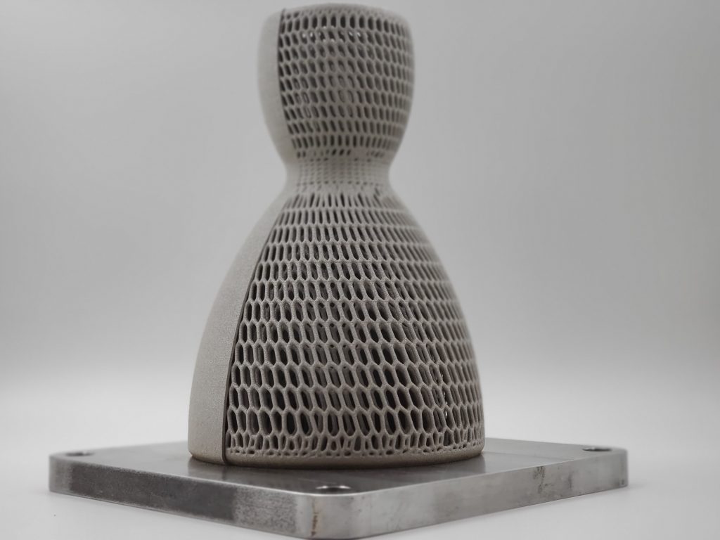
A stainless steel rocket nozzle illustrates how increasingly complex AM geometries demand tailored thermal processing strategies. | Image Credit: Dr.O Strategies
But I expect tailored thermal strategies to become the norm as AM matures. The reason: many AM materials are produced under thermal conditions that didn’t exist when traditional heat treat standards were written.
Two developments will push beyond today’s methods.
First, custom thermal cycles designed around printed microstructures rather than inherited from legacy routes. Second, spatially selective processing (e.g., different zones needing different treatments within a single component) for multi-material and functionally graded parts.
I’m also watching in-situ heat treatment during the build — re-melting passes that serve dual purposes. This blurs the line between process and post-processing entirely.
Pat Reyes: Will future AM alloys be designed with downstream thermal processing in mind?
Dr. O: Absolutely. One of the most exciting shifts is the emergence of alloys designed specifically for AM rather than adapted from casting or forging.
Future alloys will be engineered with solidification behavior, cracking resistance, residual stress management, and post-processing response as design criteria from day one.
When you’re developing an aluminum-copper or titanium-niobium variant for LPBF, the precipitation hardening response must be part of the alloy design brief, not an afterthought.
We’re moving toward process-aware metallurgy: How does this composition behave under rapid solidification? What thermal pathways unlock our target properties? Can we design an alloy that forgives minor process variation?
Organizations embedding this thinking early — treating thermal response as a design lever — will have the advantage when scaling production.
The Next Generation of Materials
Pat Reyes: What emerging material systems should thermal processors watch?
Dr. O: Beyond Ti-6A1-4V and Inconel 718, these systems deserve attention:
High-entropy alloys: Alloys like CoCrFeMnNi (Cantor alloy) offer unusual strength-toughness combinations. Their sluggish diffusion kinetics mean standard solution treatment times may need re-evaluation; these alloys don’t homogenize on conventional schedules.
Refractory metal composites: Systems based on Tantalum-Tungsten (Ta-W) or Molybdenum Lanthanum oxide (MLA) target extreme-temperature applications. Oxidation control during heat treatment remains the critical challenge; protective atmospheres and ramp rates matter more than with conventional alloys.
Additive-specific aluminum alloys: Like Scalmalloy® (A1-Mg-Sc-Zr), these are advancing rapidly. Their precipitation behavior differs from wrought 6061 or 7075; aging cycles optimized for cast stock may miss the peak hardness window entirely.
Copper alloy systems: Grades like GRCop-84 or C17000 are gaining traction in thermal management and electronics. Their high thermal conductivity affects cooling rates during printing and heat treatment alike, requiring adjusted soak times to ensure uniform property development.
For processors expanding into AM services: build relationships with alloy developers early. These materials move faster than published standards can keep up.
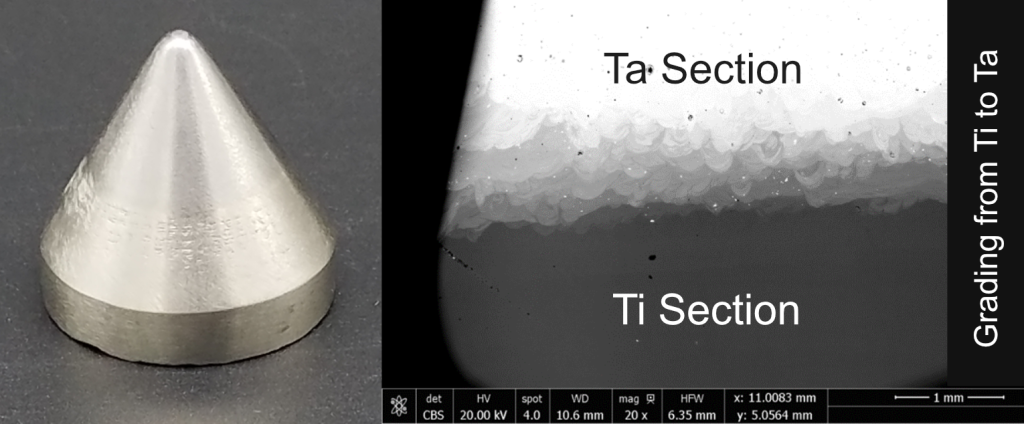
A laser powder bed fusion component with titanium-to-tantalum material gradient highlights the growing role of thermal processing in functionally graded materials. | Image Credit: Dr.O Strategies
Pat Reyes: How might nanomaterial-enhanced systems affect thermal processing?
Dr. O: This is where my focus has been most intensive, and I see both significant opportunity and genuine complexity.
Nanomaterials can refine grain structure, suppress hot cracking, and unlock new precipitation mechanisms. But they also introduce new variables: agglomeration risk, inconsistent dispersion, unexpected interactions during thermal cycling.
The challenge is that nanomaterial behavior under heat treatment doesn’t follow bulk-phase predictions. You might get beneficial grain refinement in one temperature window and particle coarsening in another. A “standard cycle” for a nanoparticle-modified alloy may produce fundamentally different results than for its conventional counterpart.
Where I see real promise: alloys engineered to leverage nanoparticles for localized property enhancement. Imagine a turbine blade where coating regions respond differently to thermal treatment than the core. Spatial control without complex assembly.
Building the Future Together
Pat Reyes: Where do you see the greatest opportunities for collaboration?
Dr. O: The biggest opportunity is moving collaboration upstream. Involve thermal processing specialists before the alloy is finalized and the first layer is printed, not after.
Thermal processing professionals understand phase transformations, microstructural control, and property optimization. Those insights can shape alloy development and process qualification from the start.
Three areas stand out:
Data sharing: Alloy suppliers publish compositional specs; heat treaters run their cycles. We need closed-loop data. What thermal paths actually deliver target properties for printed microstructures? Without this feedback, progress stalls.
Co-developed qualification: Aerospace and medical certification is expensive. Joint efforts between materials developers, machine OEMs, and thermal processors could create streamlined pathways instead of ad-hoc testing for every new alloy-part combination.
Equipment innovation: Furnace technology hasn’t evolved significantly for AM-specific needs. Opportunities exist for sensors that track microstructural transformation in real-time, and adaptive cycles that adjust based on in-situ measurements.
Pat Reyes: What misconception do you wish more thermal processors understood?
Dr. O: That heat treatment can fix poor build quality.
It’s tempting to view post-processing as a corrective step — to assume thermal cycles will close every pore, eliminate every stress concentration, transform every undesirable phase. They won’t.
Heat treatment operates within constraints set upstream. Contaminated powder, excessive lack-of-fusion defects, unpredictable stresses from poor support strategy — no thermal cycle can reverse those fundamentals.
The misconception gets expensive when organizations invest in better furnaces instead of better prints. Quality must be built in first. Heat treatment unlocks potential; it doesn’t manufacture it.
Looking Ahead
Throughout this conversation with Dr. O, one theme emerged consistently. As additive manufacturing matures, thermal processing is becoming less about only completing material processing and more about unlocking material performance not found in traditional processing methods. Dr. O emphasizes that alloy chemistry, build strategy, process parameters, and heat treatment have always been interconnected. The difference today is a growing recognition that optimizing additive manufacturing requires materials scientists, additive manufacturing engineers, and thermal processors to collaborate from the earliest stages of design rather than working sequentially through the production process.
The takeaway is clear: the next chapter of additive manufacturing offers heat treaters more than new work — it offers a seat at the table. By contributing to process qualification, materials development, and production optimization, thermal processors can help shape the future of advanced manufacturing instead of simply responding to it.
About The Expert:
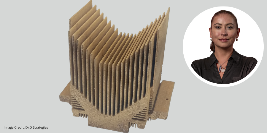
Olga “Dr. O” Ivanova Founder Dr.O Strategies
Olga “Dr. O” Ivanova is the founder of Dr.O Strategies, where she helps organizations align materials development, additive manufacturing, and commercialization strategies. An Additive Manufacturing Users Group (AMUG) Distinguished INnovator Operator (DINO) Award recipient, she advises manufacturers, startups, and investors on process qualification, alloy development, and technology adoption, with a focus on moving emerging innovations from the laboratory to scalable production.
Main image shows an LPBF copper heat sink with thin fins, which demonstrates the complex geometries that require designers and thermal processors to optimize material performance together. | Image Credit: Dr.O Strategies
Global commercial heat treater Bodycote is expanding vacuum heat treatment, hot isostatic pressing (HIP), and powder metallurgy capabilities across its eastern U.S. network. The investments increase thermal processing capacity for the aerospace and defense manufacturers, supporting production of critical metal components while helping clients meet demanding quality and delivery requirements.
Bodycote has announced a series of investments totaling several million dollars across its East Coast U.S. network. The program includes new vacuum heat treatment equipment, expanded HIP capacity, and additional powder metallurgy and additive manufacturing support capabilities at facilities in New Jersey, Massachusetts, and South Carolina. The investments also form part of its broader North American expansion program, which includes the opening of its Fairfield, Ohio, facility and the acquisition of Spectrum Thermal Processing.
Heidi McNary President, Global Aerospace, Defense and Energy Bodycote
“These investments reflect our ongoing commitment to the high-growth, high-value aerospace and defense sectors,” said Heidi McNary, president of Global Aerospace, Defense and Energy at Bodycote. “Heat treatment and thermal processing play a vital role in improving the properties of metals and alloys and extending the service life of mission-critical components. By investing in capacity and capability today, we are ensuring we can support client growth for years to come.”
The investment includes the installation of a new two-bar, front-loading vacuum furnace at Bodycote’s Roselle, New Jersey, facility. Vacuum heat treatment is performed in a controlled vacuum environment that prevents oxidation and contamination while enhancing the strength, durability, and performance of critical metal parts. The furnace has completed installation and commissioning and is now available for client production, increasing capacity for aerospace, defense, and industrial gas turbine programs.
Bodycote has also modernized its Andover, Massachusetts, facility, strengthening its Powdermet, product fabrication, and HIP-based metal densification capabilities. The site designs and fabricates near-net-shape canisters used to contain powder metal before on-site HIP processing, helping clients produce complex, high-integrity components while reducing dependence on traditional casting and forging supply chains. The facility has also undergone a lean transformation to improve workflow, free up space for future growth, and help accelerate turnaround times.
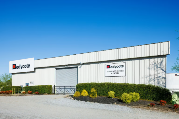
Bodycote’s Greenville, South Carolina, facility | Image Credit: Bodycote
Further investments at Bodycote’s Greenville, South Carolina, facility add HIP and heat treatment capacity for high-performance metal components, including 3D-printed parts. The site supports a more integrated post-processing route by combining HIP with precision wire EDM operations, allowing printed components to be returned ready for the next stage of production or end-use qualification. This approach helps clients simplify their supply chains, reduce supplier handoffs, and accelerate the route from printed part to application-ready component.
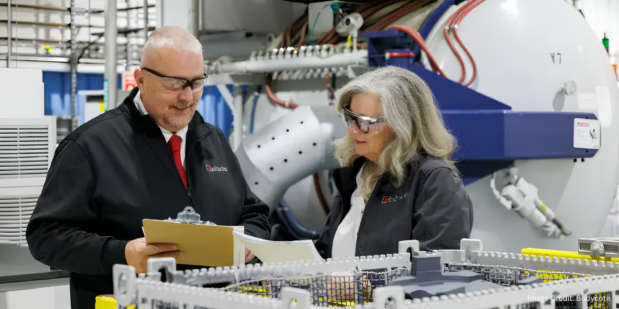
Press release is available in its original form here. Main image shows colleagues at Bodycote’s Greenville facility discussing production planning for vacuum processing that supports delivery of specialist thermal processing services for aerospace and defense clients across the eastern United States. | Image Credit: Bodycote
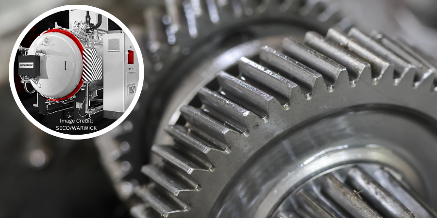
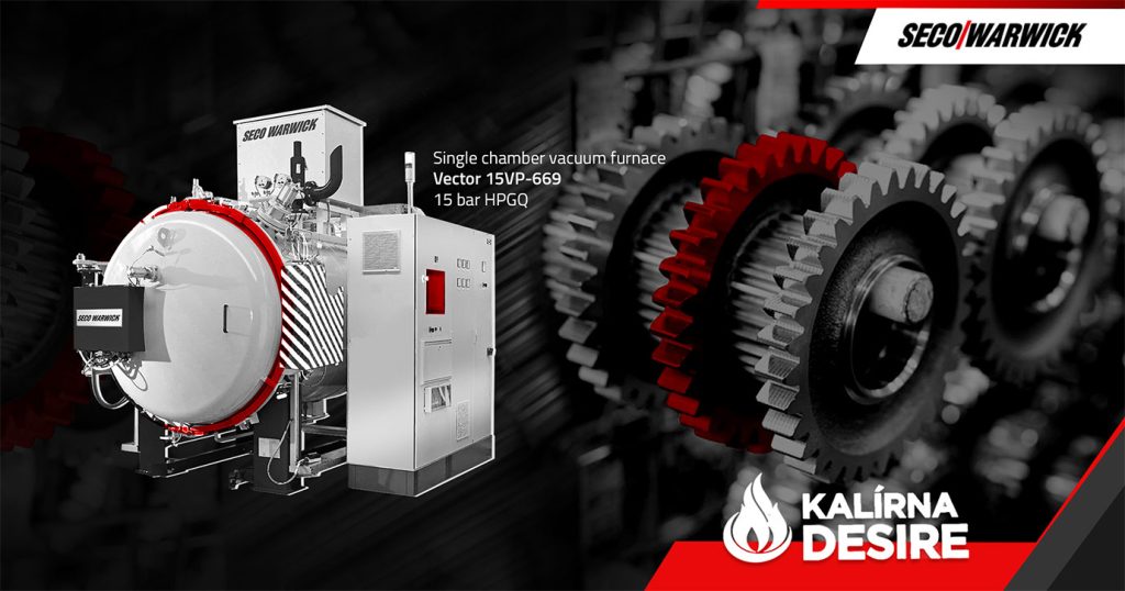
Kalírna Desire is opening a new commercial heat treat facility in a region that has so far lacked local infrastructure for vacuum hardening. The investment establishes the company’s first vacuum heat treatment operation, supporting both in-house production and a new line of commercial services for nearby manufacturers. It reflects continued demand for regional commercial heat treating capacity as companies seek shorter lead times, greater process control, and more localized supply chains.
Image Credit: SECO/WARWICK
Kalírna Desire, a Czech machining company, is establishing the operation using a Vector single-chamber vacuum furnace from SECO/WARWICK, a global industrial furnace manufacturer with operations in North America. The decision followed years of relying on a commercial heat treater located farther from its plant, resulting in longer lead times and additional transportation costs.
The furnace is configured with 15-bar absolute high-pressure gas quenching and is designed to process a range of tool and structural steel grades. Additional features include convection heating to improve low-temperature heating efficiency, directional cooling to help minimize distortion of complex parts, an isothermal quenching function for greater control of cooling profiles, and a low-pressure carburizing (LPC) option that enables surface hardening within a single integrated vacuum cycle.
Maciej Korecki Vice President of the Vacuum Segment SECO/WARWICK
“Our collaboration with Kalírna Desire is an excellent example of how vacuum technology can become a growth engine for ambitious small and mid-sized companies,” said Maciej Korecki, vice president of the Vacuum Segment at SECO/WARWICK. He added that the standard Vector furnace, configured to the client’s requirements, offers broad process capabilities while providing an accessible entry point into vacuum heat treatment.
According to a representative of Kalírna Desire, the new unit will provide greater control over a key stage of the company’s CNC machine manufacturing process while improving production planning flexibility and shortening lead times. The representative also noted that the region lacks modern vacuum hardening services, creating an opportunity to provide commercial heat treating for nearby metal processing companies and component manufacturers.
The investment highlights the importance of bringing heat treating in-house: having an in-house heat treat department gives a company a range of advantages that go far beyond cost savings on outsourced services. It provides greater process control and more flexibility to respond to client demand.
Press release is available in its original form here.
Heat TreatRadio host, Doug Glenn, sits down with Peter Sherwin, director of Strategic Marketing at Watlow, to discuss how the next generation of process control technology is being shaped by the evolving needs of the heat treating industry. Their conversation explores the role of AI, cybersecurity, workforce development, energy efficiency, and compliance in modern furnace operations, as well as how Watlow’s Edge Process Management (EPM) platform aims to bring these capabilities together in a unified system. Looking beyond a single product launch, the episode examines the trends that could define heat treating over the next two decades.
Below, you can watch the video, listen to the podcast by clicking on the audio play button, or read an edited transcript.
The following transcript has been edited for your reading enjoyment.
Introduction (1:04)
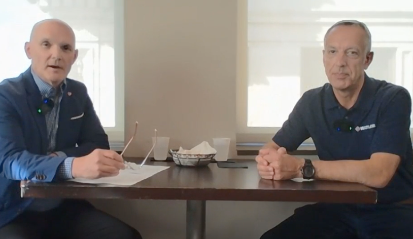
Doug Glenn: Welcome to another episode of Heat TreatRadio. I have the pleasure of actually being face-to-face here with our guest today, Peter Sherwin. Peter is the director of strategic marketing at Watlow, and we’re going to be discussing an exciting product that Watlow recently launched.
Host of Heat TreatRadio Doug Glenn (left) and Director of Strategic Marketing at Watlow Peter Sherwin (right)
There’s been some discussion in the industry about Watlow’s commitment to the thermal processing market. Can you address that?
Peter Sherwin: One of Watlow’s taglines is “wherever thermal is critical.” Obviously, thermal is very critical in heat treatment. My background is from Eurotherm, now combined with Watlow. I’ve been with the organization for around 17 years now. There was always a bias toward heat treatment within Eurotherm, but Watlow has a much broader portfolio.
Heat treatment is still very important to Watlow, but we play in a number of different spaces. The business is split into two key verticals: semiconductor and industrials. The heat treatment activity resides under the industrials banner, whether it’s automotive, aerospace, etc. So, it’s still very key to us, and I think we’ve been pushing more through our distribution channel as of late, particularly in the last twelve months.
We have been working on training and re-skilling our workforce, as well as developing the next generation of products. That’s been taking quite a bit of our focus, but we definitely have not stepped away from heat treatment.
Doug Glenn: Watlow has been dedicated to providing the resources to do that. You have been with the company when Eurotherm was standalone, when Eurotherm was Schneider, and now as Eurotherm is Watlow. Comparatively speaking, are you happy with the resources that Watlow has dedicated to the brand?
Peter Sherwin: Originally, Eurotherm was part of the Invensys setup.
Doug Glenn: Correct; I forgot that.
Peter Sherwin: But it was pretty much a standalone company. We used some of the Invensys products, like Wonderware, etc. As time went on, we were acquired by Schneider around 2014. We were folded into the energy controls business as a whole but still remained intact with Eurotherm. We had our own offices and sales team spread globally around the world. But you could tell toward the end, when Eurotherm put us up for sale and Watlow acquired us, there was a little bit of restriction in spending at that time, which probably slowed down some of the velocity of that program. Thankfully, since Watlow picked us up, we’ve gone full steam ahead. A lot of investment — I’m surprised by the amount of investment.
I’ve been in the industry for 30+ years, and it’s given me the opportunity to work across the world. I started in Europe running commercial heat treatment plants, as well as captive. Then I moved to India working with a suite of commercial shops. Then, about 18 years ago, I moved to the U.S., and it’s all on the back of heat treatment. It’s amazing to look back on. It’s a fascinating industry, and I feel as though I still owe something to the industry. This next generation of platform, for me, is something I’ve worked on for 10 years.
The Edge Process Management (EPM) Platform (6:38)
Doug Glenn: Let’s talk about that. We both attended an industry event where they said the next 4 years will determine the next 20. Essentially, this next period of time is going to be pretty critical. This product you mentioned, EPM, which stands for Edge Process Management, correct?
Peter Sherwin: Correct.
Doug Glenn: Can you describe what it is?
Peter Sherwin: EPM is a platform product. Eurotherm was started in 1965 and produced a lot of instrumentation for the heat treat industry. Everything was kind of separated. We had the best in temperature control, the best in chart recorders, originally from a brand called Chessell, and also the best in SCR power controllers. That was perfectly good for the time those came out.
But as we’re moving into this newer arena, there needs to be far more connection between those devices to address some of the challenges the heat treat industry has to wrap its arms around. For example, how do we improve compliance and make it far easier? What about energy efficiency? That 4 years will dictate the next 20 years to 2050. Think about how the planet will be at that point in time. We will need to run our furnaces far more efficiently.
Doug Glenn: I think more than any other time in history, nobody knows what the industry is going to look like 20 to 30 years down the road. It used to be that you could make a decent prediction. I’m not sure we can do that anymore.
EPM is a platform, not a discrete instrument or product, correct?
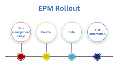
Peter Sherwin: The four years are key because of how we are rolling it out. We are releasing one part after another, so it will take a bit of time for the full platform to emerge. We start the release in July with data management, which really replaces our historical chart recorder but goes much further than that. And then, as that evolves, we will bring out control, data, and full automation over the next few years. That’s why it’s a platform. It all shares the same IO base and has the same programming software. There’s commonality across everything, but effectively you can put any of these modules anywhere that makes sense.
Doug Glenn: What is the motivating force behind the development of the platform? I’m assuming that your company, and perhaps companies even before that, had concepts of changes that would occur over the next so many years. Were some of those developments the impetus behind creating this platform? For example, workforce changes — did they have an impact on the motivation to get this platform up and running?
Peter Sherwin: I think we benefited from some of the slowing-down process of Schneider because we were able to make some architectural choices that fit with this kind of new world of AI. A lot of the web technology we’re using fits very well with AI, so we are fortunate that we can leverage some of the current technologies. As we sit here today, AI is in the news all the time. Not everyone is completely sure how all of that is going to unfold but producing a platform today and not being able to utilize AI would be a big miss. So, we integrated those features within the platform, which helps us address many of these workforce challenges.
Considerations When Building This Platform (11:35)
Doug Glenn: Those were actually two of the areas I wanted to ask you about: the workforce and AI. Some other areas I was thinking about were electrification, energy, compliance, and cybersecurity. I assume these were all considerations when you were putting together this platform.
Peter Sherwin: These areas of concern have just accelerated the need for deeply embedding all those technology features. I’m not sure we fully understand how the workforce changes are going to affect the industry and specifically in a furnace operation, but there’s definitely going to be a component of AI that is needed. As we have so many people retiring, there are people coming into the industry who have no background in processes like signing off on records and certain procedures. We have to get new hires up to speed very quickly.
This is the type of technology we’re putting into the EPM platform, to enable people to have a very short learning curve, be useful very quickly, and arm them with the likes of AI so they can enhance their capabilities.
Three forces reshaping heat treatment: an aging workforce, rising energy demands, and the rapid arrival of AI.
Energy is another one of these points. If you have separate components, it takes quite a lot to then integrate those components together to make them more useful, like a temperature controller and a power controller. You can do it, but it doesn’t have all the abilities of one device. You’re only passing certain information between the two. But if you can make that power controller have all the capabilities of control and data, you can more easily manage energy efficiency going forward. This energy piece is another trend this new platform will address.
Doug Glenn: How about the cybersecurity and compliance issues you were talking about?
Related Reading: CMMC Phase II just hit pause. As Sherwin notes in this interview, cybersecurity requirements are only rising for heat treaters — this piece breaks down what the pause does (and doesn’t) mean for defense-supply-chain compliance.
Peter Sherwin: I think that’s one major benefit of a new platform. Cybersecurity requirements have been around for a while. A few years ago, we had SB-327, a California law that came out because of hacking concerns with baby monitors. This law affected everything, though. If an industrial supplier had an internet-connected device, they had to ensure more protection on those devices. You wouldn’t believe the hurdles to then re-engineer cybersecurity into older products — not easy and kind of clunky. Our clients probably still want to slap our wrists on that, because it’s not easy for them. We had to do it because it was a law in California and CMMC. There are laws just coming into effect toward the end of next year in Europe. All of these are going to push higher and higher requirements for cybersecurity. The benefit of a new platform is that you can design these cybersecurity requirements from the start. We’re fortunate there, but it’s a big deal.
Impact of Aging Infrastructure (15:26)
Doug Glenn: How about the fact that the infrastructure most of the systems are built on now is aging out. You’re fortunate to be able to almost start from scratch. Can you comment on the aging infrastructure?
Peter Sherwin: I was having a discussion with a large global heat treater a couple of weeks ago, and they were talking about how one of their issues is that every furnace is different. With this new platform, we are looking to solve those challenges and requirements for clients. We also realize some clients want something they can just take out and put in place, a discrete instrument. So, along with EPM, we’re building what we call our level three controller. That’s a project in flight at the moment. We’ll preview it at Furnaces North America, and it’ll be released sometime in 2027.
The NanoDac recorder | Image Credit: Watlow
If you look at all the different products now across Watlow and Eurotherm, discrete products like the F40, the NanoDac, 2704, 2604, 3504 — these devices are very different, and it’s a learning curve for someone to learn and program them. We are taking the best of these devices and putting them into a new device. Even if you just want to replace a single device, we’ll have that next year.
We are trying to account for the fact that if you’ve got an operator who’s been running a particular controller for several years, how can we make that display appear the same to them? I’m hoping we’ll have some prototypes at the show so we can demonstrate. It’s kind of exciting as we come to the end of a whole suite of products from the Eurotherm and Watlow portfolio and what we’re moving into next. Not just the platform but also being able to keep some of those instruments going with a slightly new disguise.
Doug Glenn: Right, that fits into this platform. Sounds very interesting.
EPM Platform Benefits for Users (18:00)
Doug Glenn: You have talked about the clients and the users of these devices and technologies. If you can summarize briefly, why do they need this platform?
Peter Sherwin: It’s about what you were saying earlier — the next 4 years dictate the next 20. There are so many challenges for heat treaters: dealing with a lack of personnel, new hires not having the skill base, and trying to train faster. These issues are going to hit everyone.
We are not going to see a slowdown in energy initiatives, though possibly a pause in some places in the world at the moment. Why wouldn’t you want to be more energy efficient? We’ve been developing some algorithms for this new platform to enable energy efficiency. It’s not just about climate — it’s about running your operations more efficiently. The two concepts we mentioned earlier: cybersecurity, which is going to rise, and AI. How are our clients or prospective clients going to be able to leverage AI for their operations?
I don’t think that exists in today’s technology, but we’re building it. I’ve seen some of these prototypes where, instead of having to drag function blocks onto an engineering diagram and manually software-wire, it’s just a prompt. Say what you want, and it will create that architecture. It blows my mind when you see it. It’s not a big leap from what’s available to us at our fingertips today, if you use ChatGPT, Claude, etc. But it’s bringing that technology into our industry.
Building the EPM Platform (21:24)
Doug Glenn: We’ve talked a bit about what EPM is. I’m curious about what it took for Watlow to build it. It seems daunting. Can you discuss that process in terms of scalability, data integrity, etc.
Peter Sherwin: Like anything, it takes a village — a global village. We started in 2016. We had a team in India that put together a questionnaire and went around the world to key clients asking in-depth questions.
Doug Glenn: Getting thevoice of the client.
Peter Shirwin: We wanted to learn what was needed for a next-generation product. Now, as we’ve mentioned, things slowed down a bit with the handover at the end of Schneider and into Watlow. Since then, it’s been full speed ahead with Watlow.
Watlow also bought control capabilities; they had their own control line. They manufacture their products in Winona. So now we’ve introduced a Winona team into this village. The original creators were based in Worthing. These were the designers and were responsible for product/project management. We have initial manufacturing where all the Eurotherm instruments are manufactured in Poland, and we also have engineering resources in India. You can imagine all of these groups collaborating. It’s a 24-hour cycle just to build this platform. For anyone looking to build something similar, do not underestimate the amount of effort and money it takes to create something like this. It’s a commitment.
You asked about our commitment to heat treatment. This platform alone is a big commitment, because of the increased ability to do TUSs, SATs, along with process control and process recorders.
Doug Glenn: I did want to ask you about that.
Peter Sherwin: All of that has been considered in this platform. It doesn’t just apply to heat treatment, because from the Eurotherm side, historically, there were two main industries we focused on: heat treatment and life sciences. Life science is all the requirements for auditing. If you make one single change on a device, you have to make sure it was the right person that made that change and have full records. So we really just expanded on all of that intelligence that we already had to a point in some of our data management products. Where heat treatment is kind of moving, life science has already been somewhat out in front. All of that functionality supports the direction we feel heat treatment will potentially go.
Doug Glenn: It seems like a very daunting task to put something like this together.
Peter Sherwin: Daunting but exciting, and you always want to release things as soon as possible. There’s a lot of work in testing the platform. We have a brand to uphold, and we need to make sure we get something out there that works consistently. You know what the heat treatment game is like, Nadcap requirements, AMS2750 — it has to be right.
Compliance for Both Captive and Commercial Heat Treaters (25:46)
Doug Glenn: You mentioned compliance, AMS2750, and Nadcap. How will this EPM platform help a captive heat treater, as well as a commercial one?
Peter Sherwin: For us, it doesn’t really matter. It’s a furnace, and it’s about how best to control that furnace. It starts with the analog input card. You have to get that right for everything else to follow. Much of the development was around how we make a card that meets the requirements of not just a process controller, but also a field test instrument. How can we get that accuracy level in that card so it can be used across anything and isn’t restricted? And, obviously, we need to do it in a cost-effective manner so a commercial or captive heat treater can actually afford it.
We had an R&D project that looked at various ways of doing this. The analysis concluded that errors with the cold junction compensation (CJC) had the biggest impact on accuracy, so we developed a method of CJC. Essentially, it’s like having a very accurate sensor at every junction. That’s what we have on our IO cards. It’s patented, so anyone can go out and look at the details of the patent. Ultimately, it meets process control requirements and field test requirements, which then means you have the possibility, per furnace, to do process control, SAT, and TUS on the same platform. There are some restrictions on Nadcap. You have to mark that this module’s doing an SAT, these modules are doing a TUS, but it’s all common, so you can then share that information, which improves compliance.
AI and Running Processes (28:25)
Doug Glenn: I want to come back to AI. How is this platform going to help end users in running processes? Is there anything in the system, as far as AI goes, that would help?
Peter Sherwin: The ability to pull data and control together means we can start to look at the set-point program as the cycle is running. One of the new functions we’re creating is something called Batch Validator. Think from an operator’s point of view about what they need to do as the process is running, when it finishes, and to sign off and make sure it meets all its requirements. Typically, today, they may need to refer to some other guidance that specifies that this run must be within this tolerance at this level or that it’s had a guaranteed soak between these soak time points. It’s not easy for an operator to see whether the requirements has been met or not, because it’s just a line. That’s the one thing AI and Batch Validator will do — overlay the specifications for that run of the process and show very clearly if it’s deviated or not. It takes that kind of human error and guesswork away from an operator and gives them more information.
Doug Glenn: Do the current standards allow for an automated check on the validation of the load, or will that have to change?
Peter Sherwin: I fully believe in “human in the loop.” Obviously, I’m human. So, there will always be a check. But this really helps as an operator aid, because it’s just checking the screen. Ultimately, the person signing off has to be a real person.
The Future of Heat Treating (31:11)
Doug Glenn: To wrap up, tell us what you think the future of heat treating will look like.
Peter Sherwin: That’s a really good question. It depends on the time scale. I think we’re kind of clear about efficient and reliable running for the next few years. We know we can help with that, but how is it going to structurally change?
I think the operator is going to have a much, much bigger role. There have been less operators in plants. But think about maintenance skills, quality experience, and personnel retiring from the industry. We will have a real problem unless we arm the operator with the ability to do quality, a level of maintenance, and even purchasing.
I think the operator of the future is going to be very multi-skilled but also assisted by AI. We’re seeing it in different areas of our business, how people are moving and taking on more responsibility because of AI. Correlate that with a future where the operator’s going to be that key person and may not require anyone else around to fully run that furnace and run it profitably, with a minimum amount of energy, and making sure it has all the right consumables to keep on running. They’ll manage that whole operation. I think that will be a trend into the future.
Doug Glenn: That is actually a very interesting trend, because with the use of AI, I would expect to see less operators, but I like your perspective. We’ll have to come back in ten years and see how well it panned out.
About the Guest
Peter Sherwin Director of Strategic Marketing Watlow
Peter Sherwin leads strategic marketing at Watlow and brings more than 30 years of experience across heat treatment, industrial technology, business development, and product marketing. His career has included leadership roles with Watlow, Schneider Electric, DOWA HighTemp Furnaces, and Aalberts surface technologies, with experience spanning the United States, United Kingdom, and India. He also holds an MBA from Henley Business School.
Heat Treat Todaypublishes twelve print magazines a year and included in each is a letter from the editor. This letter is from the June 2026 Sixth Annual Buyers Guide Issueprint edition. In today’s letter,Bethany Leone, managing editor at Heat Treat Today, shares her insights on why a print directory still earns its place in an engineer’s toolkit.
The physical act of flipping pages, folding corners, and marking up listings creates a kind of accidental learning that a search bar can’t replicate. And the guide serves everyone differently — metallurgists, maintenance managers, and newcomers still learning the industry’s vocabulary all get something different out of it.
I’m a fold-the-spine-backwards kind of person. Chaotic annotate-at-an-angle kind of researcher. Audiobooks were designed to protect documents from people like me. But full immersion is sometimes the only way to really use information designed to help you learn or answer a question.
While the other issues in this magazine contain a slew of articles and stories to inspire and teach North American heat treaters about their equipment and processes, this issue is the industry directory. Its process-driven structure is designed to make the directory a practical next step for engineers and decision-makers evaluating their options.
A central use is finding out “who’s who” even before you need to call an equipment supplier or process provider. This can easily be done online at www.heattreatbuyersguide.com too, but in print, comparison becomes physical. Your eyes move faster than tabs open. A folded page, a pen mark, and a highlighted listing become part of the evaluation process itself.
Additionally, it is a tool to learn what’s outside your primary area of expertise. Search bars are excellent for finding answers to questions you already know to ask. Directories are different. They expose adjacent technologies, unfamiliar process names, and companies you may not have encountered otherwise. This accidental learning is hard to replicate online.
For an in-house heat treat operation mainly focused on annealing processes for steel grades but looking to enhance hardness profiles, Heat Treat Buyers Guide introduces you to the range of equipment, processes, and suppliers involved. Mark these, circle the companies, or leave a half page fold for your future self when it comes time to make a process improvement decision. While some sections may not matter today, a new alloy, distortion issue, or throughput challenge makes those folded corners and handwritten notes the starting point of the next improvement project.
The wide reach of this tool is critical for heat treating, a process dependent on an interconnected network of specialties. At my last trade show, an engineer who had transitioned from aerospace into furnace manufacturing told me, “Surprisingly complex! I had not anticipated all that goes into engineering a furnace. It is very different than aerospace, and not at all simple.” Every process step has its own expertise, from fixturing, atmosphere control, and quenching to testing, software, and beyond.
The table of contents provides the main equipment categories with color tabs that replicate on the pages of the corresponding sections. Be sure to check out the final few tabs which indicate listings for commercial heat treaters and a few leading consultants in the heat treat industry closer to the end.
The most representative categories to page through include:
Aluminum Heat Treating
Annealing
Hardening, Quench & Temper
Vacuum Heat Treating
Induction Hardening
Solution Treating & Precipitation Hardening
In line with new heat treat technology developments are increasingly represented categories around vacuum:
Vacuum Furnaces
Vacuum Carburizing
High-Pressure Gas Quench
Vacuum Hardening
Vacuum Brazing
The guide serves different purposes depending on who opens it. A metallurgist may use it to identify process capabilities. A maintenance manager may use it to source replacement systems or atmosphere components. A young engineer may simply use it to learn the vocabulary of the industry.
Whether you keep yours tidy and pages well-thumbed or take the closest sharpie to mark your next hit list, use this directory to better understand your options within the North American heat treat industry.
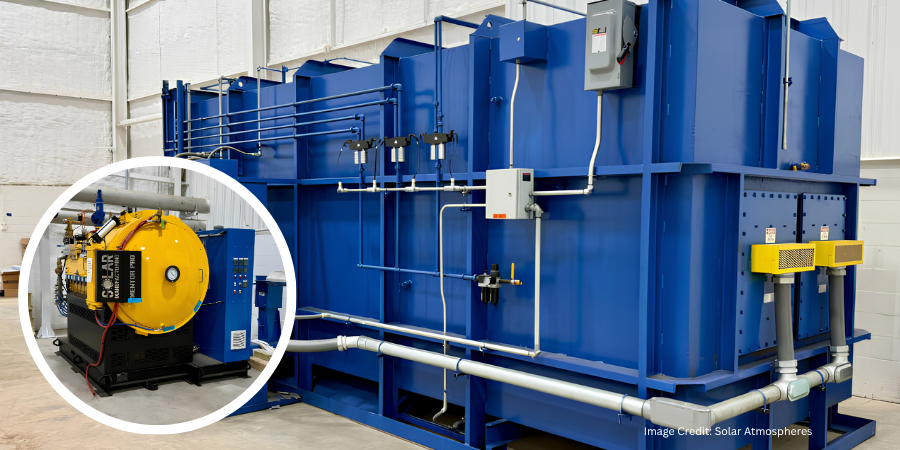
Solar Atmospheres, a commercial heat treater, is preparing to expand vacuum heat treating capacity in the Northeastern United States as construction progresses on its newest facility in Berlin, Connecticut. The 28,000-square-foot operation remains on schedule to begin serving clients in the fourth quarter of 2026.
Image Credit: Solar Atmospheres
Construction and refurbishment continue at the future home of Solar Atmospheres Connecticut, where several vacuum furnaces have already been installed. Office areas are nearing completion, while work continues on the facility’s piping, electrical systems, and supporting infrastructure.
Located in the Spruce Brook Industrial Park, the new facility is expected to expand the company’s vacuum heat treating capabilities throughout the Northeast when it opens later this year.
Press release is available in its original form here. Related Reading: Solar Atmospheres acquired the 28,000-square-foot Connecticut facility in late 2025, laying the groundwork for the company’s Northeast expansion. Click here to read more.
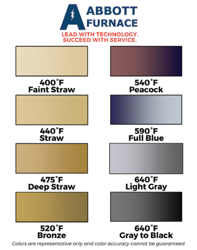
Ask The Heat Treat Doctor® has returned to bring sage advice to Heat Treat Today readers and to answer your questions about heat treating, brazing, sintering, and other types of thermal treatments as well as questions on metallurgy, equipment, and process-related issues. In this installment, Dan Herring explores the heat tint colors that form on stainless steel during heating and cooling — how the surface oxide layer thickens and shifts through straw, bronze, peacock, and blue hues at specific temperatures — and explains the factors, such as chromium content, oxygen levels, time, and surface roughness, that influence how and when these colors appear.
This informative piece was first released in Heat Treat Today’sJune 2026 Sixth Annual Buyers Guide Issue print edition.
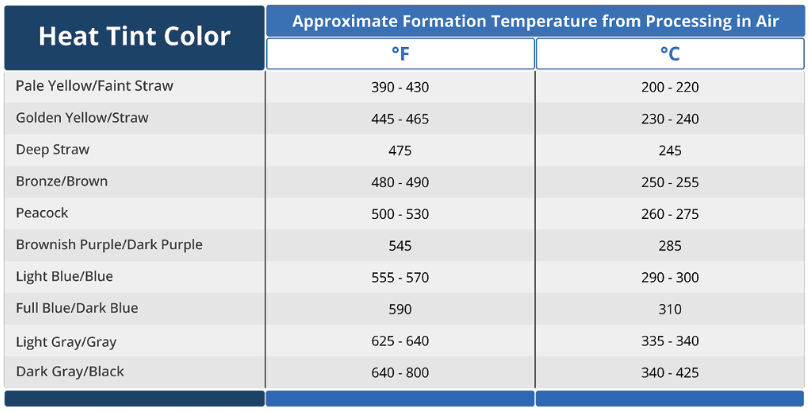
Most heat treaters, engineers, and clients are familiar with temper colors on steels (Herring 2014, ASM International 1991) and often assume that these color tints (hues) are the same for stainless steels (Table A). However, there are subtle changes that are worth noting. Let’s learn more.
Table A. Heat Tint Color Chart for Stainless Steels | Source: The HERRING GROUP, Inc.
The Science Behind Heat Tint Colors
Figure 1. Examples of color tints | Image Credit: Abbott Furnace Company
When stainless steel is exposed to an air atmosphere, or a high dew point moisture-laden atmosphere during heating or cooling, its surface changes color; that is, a thin oxide layer forms on the surface (Figure 1). This heat tint color (aka temper color) is caused by a progressive thickening of the surface oxide layer.
As most of us know, an invisible (aka passive) layer occurs naturally on stainless steels. It is extremely thin, typically in the order of 1 to 3 nanometers (3.93 x 10⁻⁸ to 1.18 x 10⁻⁷ inches) thick.
Upon exposure to air during heating or holding at temperature, this oxide layer grows in thickness. When it is approximately 20–30 nanometers (7.87 x 10⁻⁷ inches) thick, it starts to become visible to the human eye as a light-yellow or straw yellow color tint.
As the oxide layer becomes even thicker it transitions from almost transparent to a variety of different colors (e.g., bronze, peacock, blue).
As the oxide layer thickness increases from 20 nm to roughly 50–100 nm (1.97 x 10⁻⁶ to 3.94 x 10⁻⁶ inches), the colors deepen changing to a golden yellow, to a deep straw, to a bronze or golden brown, to peacock (a purplish-blue), to full blue, then light gray, and finally dark gray.
Above 100 nm (3.94 x 10⁻⁶ inches,) up to approximately 850 nm (3.35 x 10⁻⁵ inches) the tint transitions from dark blue/gray to black.
Such shallow oxides are known to enhance corrosion resistance on various stainless steel grades.
Factors Influencing Color Change
Several factors influence the type of oxide that forms on the surface, its adhesion to the surface, and how quickly the thickness of the oxide will grow (BSSA).
Chromium
From a purely material standpoint, the single most important element is the chromium (Cr) content of the stainless steel. To be classified as a stainless steel, it must contain a minimum of 10.5–11% Cr. The higher the chromium content, not only is the alloy more heat resistant, but the heat tint color formation mechanism is retarded.
Oxygen Content
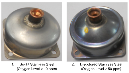
Figure 2. Bright and discolored stainless steel parts run in a continuous brazing furnace. The discolored part was caused by room air infiltrating into the cooling zone at high levels (> 50 ppm) from the exit of the furnace. | Image Credit: The HERRING GROUP, Inc.
Another factor that influences the rate of oxide formation and the thickness of the oxide is the oxygen content of the atmosphere (Figure 2). Air is approximately 21% oxygen. Nitrogen, however, will typically have between 0.001%–1% oxygen depending on its source, while argon typically has between 0.0005%–1% oxygen. By contrast, water vapor contains around 89% oxygen.
As anyone who has run stainless steel in vacuum furnaces knows, stainless parts can be discolored due to such factors as an air leak during heating or cooling, a pinhole water leak in a heat exchanger which opens during cooling in one temperature range and close again at a lower temperature, or air infiltration in the backfill gas supply.
Time
Time plays a factor as well. The longer the exposure time, the deeper the heat tint color.
Surface Roughness
Finally, surface roughness influences both the rate of oxidation and the heat tint color formation. Rougher surfaces tend to oxidize at a higher rate and with all other factors remaining the same, deeper colors are produced.
Final Thoughts
Knowing the color tints that may form on the surface of stainless steel is invaluable in helping the heat treater explain this phenomenon to their clients and/or troubleshoot their equipment and processes in an attempt to minimize or eliminate undesirable surface tints on the stainless steel parts that they run.
References
Herring, Daniel H. 2014. Atmosphere Heat Treatment, Volume I (Section 5.8). BNP Media Group II.
British Stainless Steel Association (BSSA). bssa.org.uk.
About the Author
Dan Herring “The Heat Treat Doctor” The HERRING GROUP, Inc.
Dan Herring has been in the industry for over 50 years and has gained vast experience in fields that include materials science, engineering, metallurgy, new product research, and many other areas. He is the author of six books and over 700 technical articles.
Outokumpu Stainless USA will upgrade its secondary metallurgy operations with a new 180-ton twin ladle furnace at its Calvert, Alabama, facility. The project will add electrical heating capacity following argon oxygen decarburization processing, improving operational flexibility and supporting stainless steel production.
Outokumpu has contracted Primetals Technologies to supply the furnace, which will replace a ladle treatment stand installed in 2012. Startup is scheduled for March 2028.
At the Calvert facility, Outokumpu melts up to 100% stainless steel scrap in an electric arc furnace before processing the material in an oxygen decarburization (AOD) converter. Upgrading one of the plant’s two ladle treatment stands will add electrical heating capacity after the converter and provide greater flexibility in the AOD process.
The project will use the plant’s existing layout and foundation. Primetals Technologies’ scope includes a water-cooled ladle cover integrated with a swing gantry system, an electrode conducting arm with a high-current system, automated argon lancing equipment, a hydraulic system, a power solution, Level 1 automation, and the supplier’s Melt Expert electrode control system.
The Melt Expert system provides dynamic control of the melting process to improve process stability, furnace productivity, and energy consumption. The upgrade is also expected to reduce the plant’s carbon footprint.
Press release is available in its original form here.