IN 718 Part 1: History, Applications, and Production
Today’s Technical Tuesday highlights this first installment in a multi-part series by Nikolai Alexander and The Heat Treat Doctor® Daniel H. Herring, which introduces Inconel® Alloy 718, one of the most widely used nickel-based superalloys, tracing its history, applications, and production fundamentals. Understanding why this alloy performs so well in extreme environments is critical as manufacturers consider material choices available for demanding components, especially alloys more typically sourced outside of one’s own industry. As demanding performance capabilities are being required of new engineered solutions, selecting the right alloy becomes a strategic decision to meet the need for higher temperatures, pressures, and corrosive environments.
This informative piece is from Heat Treat Today’s February 2026 Annual Air & Atmosphere Heat Treating print edition.
History
Inconel® Alloy 718 (IN 718) is a nickel-iron base superalloy known for its exceptional strength, resistance to high temperatures and ability to withstand harsh environments, where oxidation, creep, and corrosion resistance are paramount. The alloy was created by Dr. Herbert L. Eiselstein, who began his research in 1958, culminating in a patent assigned to The International Nickel Company in 1962 (U.S. Patent No. 3,046,108). In the many years since its creation, IN 718 remains the most widely used of all superalloys due to its availability in both wrought and cast products with high strength and stress-rupture life up to 650°C (1200°F), good hot working characteristics, castability, weldability, and cost effectiveness — all in an alloy with nominally 18% iron! The alloy’s superior performance is due in large part to its unique strengthening mechanisms.
There are different classifications of a superalloy, all based around the predominant metal present in the alloy. These categories include (Akca and Gursel 2015):
- Nickel-based
- Iron-based
- Cobalt-based
The microstructural design makes IN 718 one of the best alloys for service applications below 650°C (1200°F) (Loria 1988, Herring 2011). It is widely used in extreme environments where components are subjected to high temperature, pressure, and/or mechanical loads. When heated, IN 718 forms a thick, stable, passivating oxide layer that protects the surface from further attack.
The alloy retains strength over a wide temperature range, making it attractive for high-temperature applications where materials like aluminum and steel would fail due to creep caused by thermally induced crystal vacancies. Inconel’s high-temperature strength is developed through heat treatment by solutionizing and precipitation hardening.
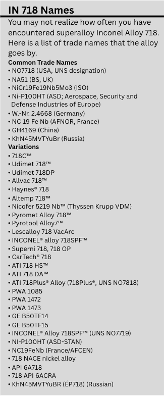
IN 718 is an alloy used around the world, but you might know it better by one of a variety of trade names (see sidebar).
The alloy has been modified numerous times to extend its operating temperature and service life. The alloy is readily available in all of these modified variations, each having slight differences in chemistry, cast and wrought processing methods, and heat treatments.
Applications
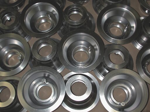
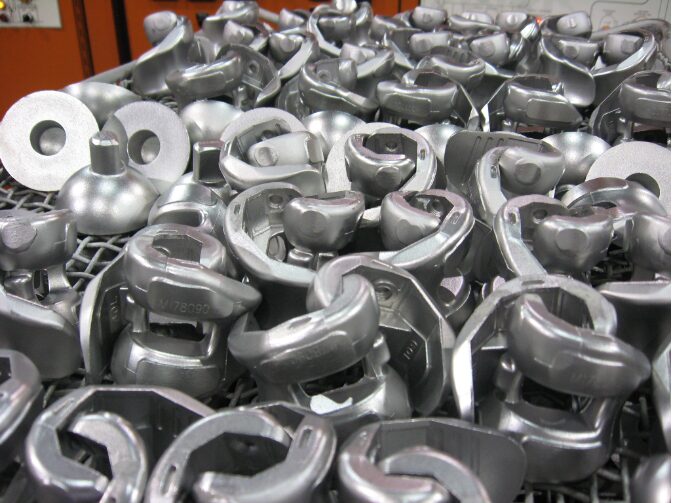
There is a wide variety of IN 718 applications across many industries, including aerospace, nuclear, oil and gas, automotive, motorsport, chemical processing, non-nuclear power generation, medical, tooling and molds, and fire protection systems.
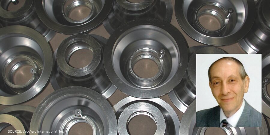
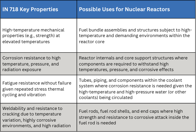
In the automotive and motorsport industry, IN 718 is used for turbocharger rotors, exhaust manifolds, and valve springs in high-performance engines, such as those found in Formula 1 or the 24 Hours of Le Mans race cars. Naval warships are also purported to use IN 718 for components in their nuclear reactors (Table A).
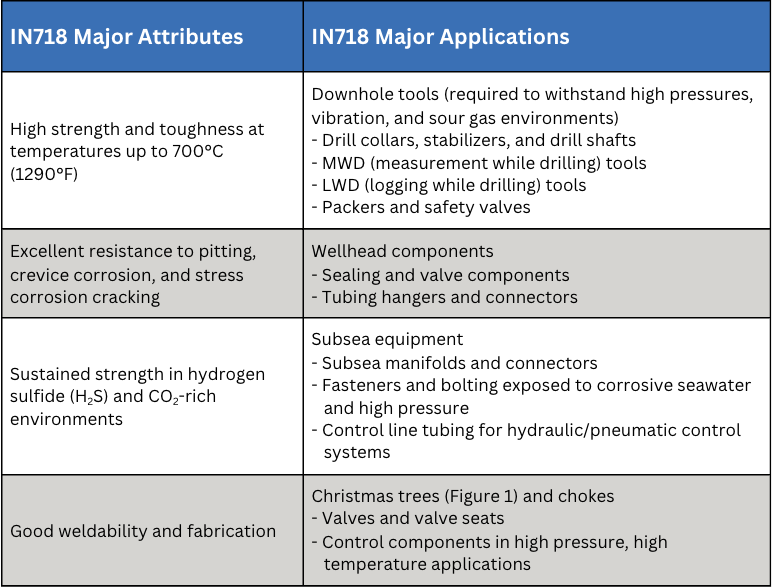
Perhaps surprisingly, IN 718 is also widely used in the oil and gas industry, which in addition to its many other benefits has remarkable resistance to sulfide and chlorine stress corrosion cracking at both high and low temperatures (Table B). Stress corrosion cracking is a failure mechanism that is caused by a combination of environment, a susceptible material, and the presence of tensile stress. Oil and gas applications like downhole tools, wellhead components, and subsea equipment benefit from IN 718’s other valuable properties as well, some of which include:
- High strength and toughness at temperatures up to 700°C (1290°F)
- Excellent resistance to pitting, crevice corrosion, and stress corrosion cracking
- Sustained strength in hydrogen sulfide (H2S) and CO2-rich environments
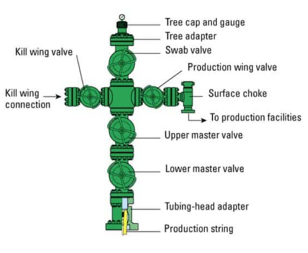
- Good weldability and fabrication
Continuous innovations in processing and material chemistry have enhanced superalloy properties resulting in the extension of its use into other industries, such as the energy and more conventional transportation sectors (Loria 1988).
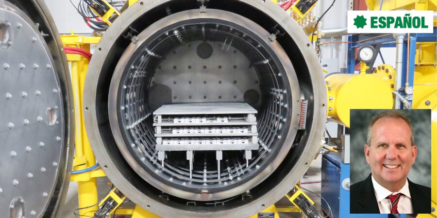
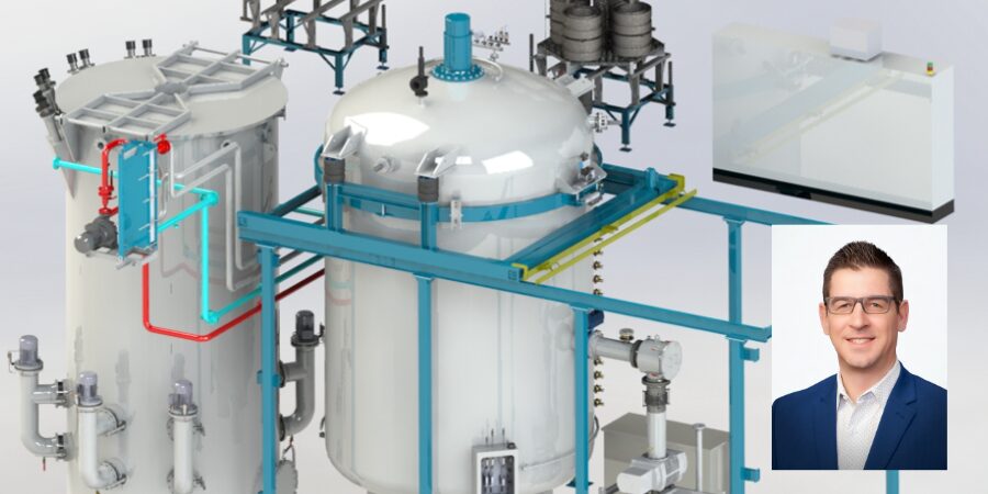
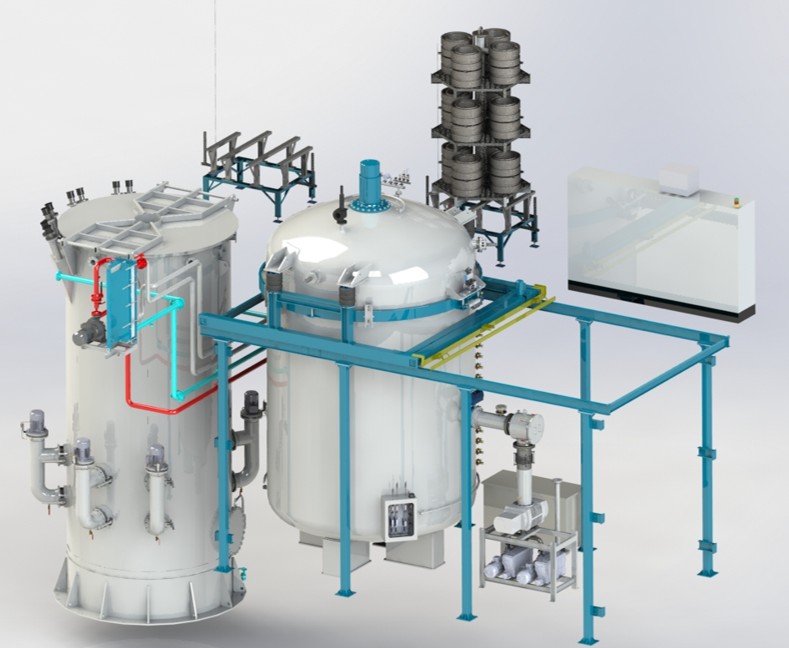
Production Methods
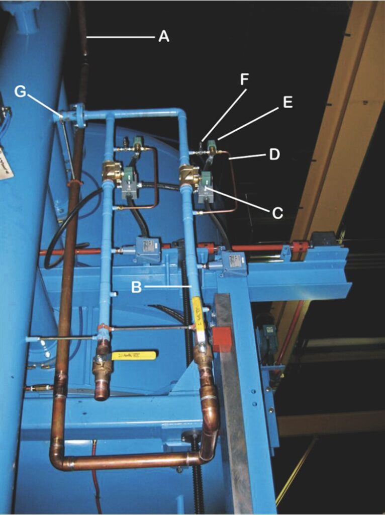
IN 718 is available in cast and wrought alloy form and follows a stringent production process (Figure 2). Basic melt practices are used, such as vacuum induction melting (VIM), vacuum arc remelting (VAR), and electro-slag remelting (ESR).
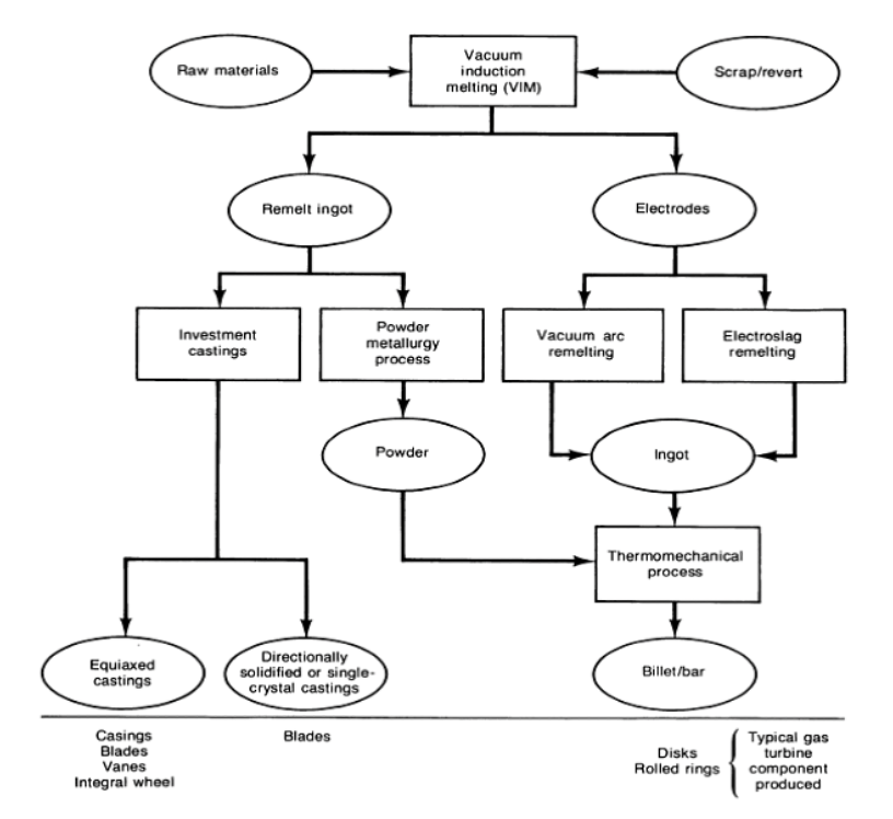
VIM
The VIM process produces liquid metal under vacuum in an induction-heated crucible. It is used as a primary melting step in the route to producing wrought and cast products. Before being melted, the raw material can be refined and purified, and its composition can be controlled. VIM has been widely used in the manufacture of all types of superalloys, which must be melted under vacuum or in an inert gas atmosphere because of their reactivity with atmospheric oxygen and nitrogen.
VAR
The VAR process, a secondary melting technique, converts VIM-processed electrodes into ingots whose chemical and physical homogeneity have been significantly improved. In this process, a stub is welded to one end of an electrode, which is then suspended over a water-cooled copper crucible. Next, an arc is struck between the end of the electrode and the crucible bottom. Maintaining the arc generates the heat required to melt the electrode, which drips into the crucible and can subsequently be poured into molds. Many inclusions can be removed by flotation or chemical and physical processes before the molten material solidifies.
ESR
The ESR process, another secondary melting technique, is similar to the VAR process, but with notable differences. Remelting does not occur by striking an arc under vacuum. Instead, an ingot is built up in a water-cooled mold by melting a consumable electrode that is immersed in a slag, which is superheated by means of resistance heating. Rather than operating in a vacuum, the process is conducted in air under the molten slag. During melting, metal droplets fall through the molten slag, and chemical reactions reduce sulfur and nonmetallic inclusions. Both ESR and VAR processes allow directional solidification of an ingot from bottom to top, yielding high density and homogeneity in its macrostructure, as well as an absence of segregation and shrinkage cavities.
Casting Methods
IN 718 can also be produced by several casting methods. The most common of these are investment casting and (vacuum) die casting:
- Investment casting: This process involves creating a wax pattern, coating it with a ceramic shell, melting out the wax, and then pouring molten IN 718 into the ceramic mold.
- Vacuum die casting: This method uses a vacuum to fill the mold, resulting in a refined grain structure, minimal porosity, and good dimensional reproducibility, making it suitable for components like airfoils.
- Sand casting: This method is far less common due to its inherent limitations in precision and surface finish, but the technology has been used for large castings.
A Metallurgical Perspective: The Role of Gamma Prime and Double Prime
IN 718 is a precipitation hardening superalloy. Its principle strengthening phases are gamma prime (γ′) or Ni3Al and gamma double prime (γ″) or Ni3Nb. The relationship between these precipitates (and others) and the gamma (γ) nickel matrix is critically important. For example, the coherency strain (i.e., the elastic deformation that occurs between two phases when their lattice structures do not perfectly match) is due to the fact that γ′ is face-centered cubic and γ″ is body centered tetragonal. In the case of IN 718, these strengthening effects are influenced more by γ″ than γ′ (ASM International 2016, Lee et al. 2023).
In addition, IN 718 has a natural tendency to precipitate rapidly by homogeneous nucleation in the noncompressible γ matrix. Depending on chemistry, γ′ volume percentage can vary over a wide range (3%–65%). Practically speaking, creep strength is proportional to volume percent over this range at temperatures between 700–980°C (1290–1800°F). As a result, the ratio of titanium to niobium/aluminum is key to hardening. High ratios imparted by niobium assure high strength at intermediate service temperatures around 600°C (1110°F). For higher service temperatures, higher aluminum content and molybdenum additions minimize the γ and γ′ mismatch, thus contributing to more stable alloys (Decker 2006, Guan et al. 2023).
Finally, the size and shape of these precipitates is important; larger precipitates enhance the strengthening effect. Key to the formation of these two precipitates is the aging treatment temperature, time, and alloy composition. According to existing research, higher aging treatment temperatures and longer times can lead to an increased amount of γ″ while extended aging coarsens the γ′ and γ″ particles, potentially leading to a reduction in strength and creep resistance. Furthermore, the composition ratios of Al, Ti, and Nb in the alloy influence the shapes of γ′ and γ″ precipitates, forming so-called co-precipitates that also affect the properties (Table C).
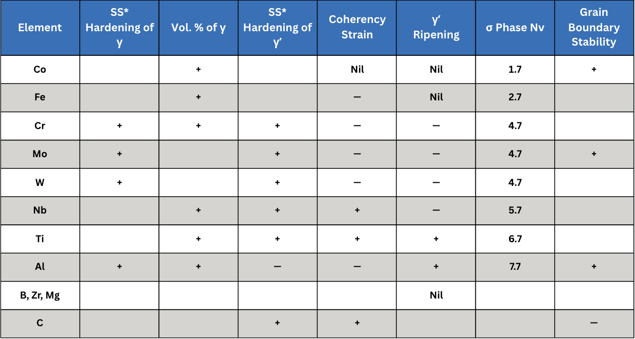
Table C. Effect of Various Alloying Elements (Data Reference: Decker 2006)
The highest strength and hardness, coupled with reduced impact toughness, have been observed after heat treatment at 718°C (1325°F), due to an increase in the size and quantity of γ′ and γ″ precipitates.
In addition, as a result of surface analysis of Charpy bars, intergranular fracture occurs due to abundant small-sized precipitates formed within the boundary. In the case of the Charpy impact test, the absorbed energy decreases as the aging temperature increases. The formation of carbide, γ′ and γ″ precipitates can reduce the impact toughness of materials because precipitates may cause more obstacles to dislocation movement and promote crack initiation and propagation (Lee et al. 2023).
This article’s discussion continues in Heat Treat Today’s Annual Aerospace Heat Treat (March 2026) print edition to address heat treatment methods for this superalloy.
References
Akca, Enes, and Gursel, Ali. 2015. “A Review on Superalloys and IN718 Nickel-Based INCONEL Superalloy.” Periodicals of Engineering and Natural Sciences 3 (1): 15–27.
ASM International. 2016. ASM Handbook, Volume 4E: Heat Treating of Nonferrous Alloys. ASM International.
Babu, S. S., N. Raghavan, J. Raplee, S. J. Foster, C. Frederick, M. Haines, R. Dinwiddie, M. K. Kirka, A. Plotkowski, Y. Lee, and R. R. Dehoff. 2018. “Additive Manufacturing of Nickel Superalloys: Opportunities for Innovation and Challenges Related to Qualification.” The Minerals, Metals & Materials Society and ASM International: 3764–3780.
Bradley, Elihu F., ed. 1988. Superalloys: A Technical Guide. ASM International.
Chandler, Harry, ed. 1996. Heat Treater’s Guide: Practices and Procedures for Nonferrous Alloys. ASM International.
Croft Systems. n.d. “The Difference between a Wellhead & Christmas Tree.” https://www.croftsystems.net/oil-gas-blog/the-difference-between-a-wellhead-christmas-tree/
Decker, R. F. 2006. “The Evolution of Wrought Age-Hardenable Superalloy.” Journal of The Minerals, Metals & Materials Society, September: 32–36.
del Bosque, Antonio, Fernández-Arias, Pablo, and Vergara, Diego. 2025. “Advances in the Additive Manufacturing of Superalloys.” Journal of Manufacturing and Materials Processing 9 (215): 1–31.
Eliasen, K. M., T. L. Christiansen, and M. A. J. Somers. 2010. “Low-Temperature Gaseous Nitriding of Ni-Based Superalloys.” Surface Engineering 26 (4): 248–255.
Guan, Hao, Wenxiang Jiang, Junxia Lu, Yuefie Zhang, and Ze Zhang. 2023. “Precipitation of δ Phase in Inconel 718 Superalloy: The Role of Grain Boundary and Plastic Deformation.” Materials Today Communications 36 (August).
Herring, Daniel H. 2011. “Stress Corrosion Cracking.” Industrial Heating, October: 22–24.
Herring, Daniel H. 2012. Vacuum Heat Treating: Principles, Practices, Applications. BNP Media II, LLC.
Herring, Daniel H. 2019. “The Heat Treatment of Inconel 718.” Industrial Heating, June: 12–14.
Lee, Gang Ho, Ang Ho, Minha Park, Byoungkoo Kim, Jong Bae Jeon, Sanghoon Noh, and Byung Jun Kim. 2023. “Evaluation of Precipitation Phase and Mechanical Properties According to Aging Heat Treatment Temperature of Inconel 718.” Journal of Materials Research and Technology 27 (Nov–Dec): 4157–4168. https://doi.org/10.1016/j.jmrt.2023.10.196
Lee, Shin-Chin, Shih-Hsien Chang, Tzu-Piao Tang, Hsin-Hung Ho, and Jhewn-Kuang Chen. 2006. “Improvements in the Microstructure and Tensile Properties of Inconel 718 Superalloy by HIP Treatment.” Materials Transactions 47 (11): 2877–2881.
Loria, Edward A. 1988. “The Status and Prospects of Alloy 718.” Journal of Materials, July: 36–41.
Polasani, Ajay, and Vikram V. Dabhade. 2024. “Heat Treatments of Inconel 718 Nickel-Based Superalloy: A Review.” Metals and Materials International: 1204–1231.
Sharghi-Moshtaghin, Reza, Harold Kahn, Yindong Ge, Xiaoting Gu, Farrel J. Martin, Paul M. Natishan, Arrell J. Martin, Roy J. Rayne, Gary M. Michal, Frank Ernst, and Arthur H. Heuer. 2010. “Low-Temperature Carburization of the Ni-Base Superalloy IN718: Improvements in Surface Hardness and Crevice Corrosion Resistance.” Metallurgical and Materials Transactions A 41A (August): 2022–2032. https://doi.org/10.1007/s11661-010-0299-y
Shipley, Jim. 2023. “Hot Isostatic Pressing and AM: How to Improve Product Quality and Productivity for Critical Applications.” Metal AM 9 (3).
U.S. Patent No. 3,046,108.
Acknowledgments: This paper would not have been possible without discussions, guidance and contributions from a number of individuals in both the heat treat industry and academia.
Special Note: Inconel® is a registered trademark of Special Metals Corporation group of companies.
About the Authors:

“The Heat Treat Doctor®”
The HERRING GROUP
Dan Herring, who is most well known as The Heat Treat Doctor®, has been in the industry for over 50 years. He spent the first 25 years in heat treating prior to launching his consulting business, The HERRING GROUP, in 1995. His vast experience in the field includes materials science, engineering, metallurgy, equipment design, process and application specialist, and new product research. He is the author of six books and over 700 technical articles.

Intern
The Heat Treat Doctor®
Nikolai Alexander Hurley is a young academic, interning with The Heat Treat Doctor®.
For more information: Contact Dan at dherring@heat-treat-doctor.com.

IN 718 Part 1: History, Applications, and Production Read More »